NJQRX61CCar Alarm System
Wintecronics Ltd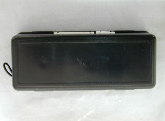
Click to zoom
Application Details
- Equipment Class
- DSR - Part 15 Remote Control/Security Device Transceiver
- Date of Grant
- Jan 31, 2002
- Application Purpose
- Original Equipment
- Date of Application
- Jan 31, 2002
- Equipment Note
- Car Alarm System
- Frequency Range
- 433.92000000 - 433.92000000
- Company
- Wintecronics Ltd
- Country
- Taiwan
Documents & Files
Document Text
Text extracted from the exhibit documents filed with the FCC. Open a document above to read the original.
Users Manual
USER’S MANUAL LCA2200 ( Long Range Auto Monitor) FCC Statement This device complies with part 15 of the FCC Rules. Operation is subject to the following two condition.(1).this device may not cause harmful interference. (2).this device must accept any interference received, including interference that may cause undesired operation Warning: Note: This equipment has been tested and found to comply with the limits for digital device, pursuant to Part 15 of FCC Rules. These limits are designed to provide reasonable protection against harmful interference in a residential installation. This equipment generates, used and can radiate radio frequency energy and, if not installed and used in accordance with the instructions, may cause harmful interference in to radiate communications. However, there is no guarantee that interference will not occur in a particular installation. If this equipment does cause harmful interference to radio or television reception, which can be determined by turning the equipment off and on, the user is encouraged to try to correct the interference by one or more of the following measures: l Reorient or relocate the receiving antenna l Increase the separation between the equipment and receiver. l Connect the equipment into an outlet on a circuit different form that to which the receiver in connected. l Consult the dealer or an experienced radio/TV technician for help. THE MANUFACTURER IS NOT RESPONSIBKE FOR ANY RADIO OR TV INTERFERENCE CAUSED BY UNAUTHORIZED MODIFICATIONS TO THIS EQUIPMENT.SUCH ODIFICATIONS COULD VOID THE USER’S AUTHORITY TO OPERATE THE EQUIPMENT. ’ 1114 Buttons’ Features: ON/OFF button: Press this button to turn receiver’s power “ ON ”, pressing a few sec will turn the power “ OFF ” Audible / Vibration alert button: While power “ON ”; Press and hold this button one sec, a “Bi Bi” is heard to confirm the pager in beep mode without icon. Upon a second press , vibration is felt to confirm the pager in vibration alert mode and will show up RESET/ Backlight button: Press this button to have backlight a few sec. During any alert, pressing of it will mute beep sound and immediately the receiver gets into a standby mode. Power source for pager receiver: 1.5 V alkaline battery x 1 piece Operation Guide: 1. POWER-ON: Icons appear along with audible sound or vibration. Then receiver gets into standby modeNote: The main system must be in the “arm mode”. 2. POWER-OFF : All active icons disappear following audible sound or vibration. Icon Guide: 1. Unlock/disarm Mode :This shows up if the car is disarmed / unlocked. During this mode, only page-out and engine-start functions can still be operated while other functions become invalid 2. Lock/arm Mode :This shows up if the car is locked. 15 sec later, the receiver makes a beep sound and displays to confirm that the car gets into ARM MODE. 3. Range Check Mode :This shows up during 5 min-range-check if pager can be receiving signal from the car’s transmitter immediately after LOCK MODE. This icon stays on within the effective range for the whole 5 min duration. It will disappear either the pager is beyond effective range or 5-min range check is over. 4. Engine Run Mode: Thiswill show up audible or vibration alert if the car’s engine is running. 5. Door Open Mode: This will show up with audible or vibration alert if the door is opened in lock / arm mode. 6. Hood Open Mode: This will show up audible or vibration alert if the hood is opened in lock / arm mode. 7. Trunk Open Mode: This will show up audible or vibration alert if the trunk is opened in lock / arm mode. 8. Light Impact Mode: This will show up audible or vibration alert if the car in lock / arm mode experiences a light impact . 9. Heavy Impact Mode: This will show up audible or vibration alert it the car in lock / arm is bumped or shaken with force. 10. Low Battery Indicator : Thiswill show up audible or vibration alert when the pager’s battery is very low. 11. Page out Call :A person in the car can send (within effective range) a page call by pushing the button on the antenna’s case to anyone carrying the receiver. He will be alerted by sound like telephone ring or vibration by his receiver. . Other System features: 1. Modes and Audible alert: Different icons and audible alert enable car owner to monitor car’s various modes. 2. Last Status Memory: After lock mode, the receiver retains the latest car status until it receives UNLOCK report feedback . It will reset itself afterwards. 3. Page-out Call button: There is a page-out call button in the center of the circular antenna case which can be used to page a person carrying receiver in case of need. 4. When the main system of the vehicle enters “ arm mode”, the status LED on the transmitter/ antenna case blinks slowly and steadily and pulse during transmission. This acts as a warning sign against any theft attempt. Code Learning of receiver :For replacement or to have a spare receiver, follow the instruction below. Turn pager’s power “OFF” first. Then press and hold the ON/OFF button for about 5 sec till one beep is heard when the receiver gets into 20 sec learning mode. Release the button and push the call-out button to transmitter a paging signal which will then be learned by the receiver still active in the learning mode. The receiver will respond with a series of beeps to confirm its success of code learning. MODEL:LCA-2200 LONG RANGE VEHICLE MONITOR INSTALLATION MANUAL l This can be installed on any vehicle with its normal voltage of 12 Volt. l LCA-2200 can work on any of the following 3 different circuit types of the vehicle to control “ON” and “OFF” modes of vehicle monitoring. Installation should be done according to the actual circuit condition of the vehicle. A Type : In this type, vehicle is installed with remote security system which has start kill output to enable main control module to operate the monitoring “ON” and “OFF” functions. 1 2 3 1105 B Type : In this type , the vehicle has neither remote-…
Text truncated - open the document above for the full version.
Block Diagram
LCA2200RXBLK.sch-1 - Tue Dec 18 09:15:51 2001 LCA2200TXBLK.sch-1 - Tue Dec 18 09:17:35 2001
External Photos
Photo 1. Front View Photo 2 Rear View 01E1850 01E1850
ID Label/Location Info
NEUTRON EMC LAB. FCC ID: NJQRX61C 5/25 2. Product Labeling 2-1. FCC ID Label 2.8 cm FCC ID : NJQRX61C 4.7cm The remained portion of label statement required by FCC is attached in the user’s manual. 2-2 Location of Label on EUT 01E1667 01E1776 01E1850
Internal Photos
Photo 3 Unit partially Disassembled 01E1850 Photo 4 Unit partially Disassembled 01E1850 01E1850 Photo 5 Unit partially Disassembled 01E1850 Photo 6 Unit partially Disassembled 01E1850 01E1850 Photo 7 Unit partially Disassembled 01E1850 Photo 8 Unit partially Disassembled 01E1850 01E1850 Photo 9 Unit partially Disassembled 01E1850 Photo 10 Unit partially Disassembled 01E1850 01E1850 Photo 11 Unit partially Disassembled 01E1850 Photo 12 Unit partially Disassembled 01E1850 01E1850 Photo 13 Unit partially Disassembled 01E1850
Operational Description
The Wintercronics Co., Ltd. Model: LCA2200 (referred to as the EUT in this report) is a Transmitter and Receiver of car alarm security system. It offers wireless remote control, ideal for use in vehicle security system to activate the function of center door lock control system and car searching except the alarm system. A major technical descriptions of EUT is described as following: A). Operation Frequency: 433.92 MHz B). Modulation : Pulse Modulation C). Antenna Designation: Non-User Replaceable (Fixed) D). Power Supply: 12V, Battery Operated. E). Receiver type : Superheterodyne Battery Operated ≤ The transmitter of this product is installed inside the car and powered by 12VCD from the cigarette lighter. The antenna used is helix type antenna. Only one carrier frequency, 433.92MHz, is provided. The transmitter includes some sensors such as vibration sensor to detect any abnormal situation of the car. The receiver is carried by the user for receiving the signal from the transmitter. ’
Schematics
ANT60B.sch-1 - Sun Dec 16 14:22:30 2001 ZP61c.sch-1 - Sun Dec 16 14:54:47 2001 ZP62CR1.sch-1 - Sun Dec 16 15:05:17 2001 zp63Cr1.sch-1 - Sun Dec 16 15:13:19 2001
Test Report
NEUTRON EMC LAB. FCC ID: NJQRX61C 1/25 MEASUREMENT/TECHNICAL REPORT APPLICTNT:Wintercronics Co., Ltd. MODEL NO.:LCA2200 FCC ID:NJQRX61C This report concerns ( check one ) : Original Grant 3 Class II Change Equipment type: 433.92 MHz Remote Controller (Transmitter) Deferred grant requested per 47CFR 0.457(d)(1)(ii)? Yes No 3 If yes, defer until: (date) We, the undersigned, agree to notify the Commission by (date) / / of the intended date of announce meant of the product so that the grant can be issued on that date. Transition Rules Request per 15.37? Yes No 3 If no, assumed Part 15, Subpart B for unintentional radiator the new 47 CFR (10-1-90 Edition) provision. Report Prepared by Testing House Neutron Engineering Inc. for Company Name Wintercronics Co., Ltd. Address 2F., No. 7-1, Ming Lee Street, Chung Ho, Taipei, Taiwan, R.O.C. Applicant Signature Apin Chang / General Manager NEUTRON EMC LAB. FCC ID: NJQRX61C 2/25 CERTIFICATION We hereby certify that: The test data , data evaluation , test procedures, and equipment configurations shown in this report were made in accordance with the procedures given in ANSI C63.4 (1992) and the en- ergy emitted by the sample EUT tested as described in this report is in compliance with con- ducted and radiated emission limits of FCC Rules Part 15. Prepared by Carol Chen Reviewed by Vincent Su Approved by George Yao Issued Date Jan. 08, 2002 Report No. NEI-FCCB-01219 Company Stamp NEUTRON ENGINEERING INC. No. 132-1, Lane 329, Sec. 2, Palain Rd., Shijr Jen, Taipei, Taiwan TEL: (02) 2646-5426 FAX : (02) 2646-6815 NEUTRON EMC LAB. FCC ID: NJQRX61C 3/25 Table of Contents 1.General Informa- 1-1 Product Description............................................................................................................4 1-2 Related Submittal(s)/Grant(s)..............................................................................................4 1-3 Test Methodology.............................................................................................................4 1-4 Test Facility...................................................................................................................4 2.Product Label- ing............................................................................................................................ Figure 2-1 FCC ID Label............................................................................................................5 Figure 2-2 Location of Label on EUT.......................................................................................5 3.System Test Configura- 3-1 EUT Configuration.............................................................................................................6 3-2 EUT Exercise........................................................................................................................6 3-3 Test Procedure.....................................................................................................................6 3-4 Limitation...........................................................................................................................7 3-5 Special Accessories...............................................................................................................7 3-6 Equipment Modifications.....................................................................................................7 3-7 Test Set-UP..........................................................................................................................8 3-8 Test Equipment......................................................................................................................9 4.Block Diagram(s).........................................................................................................................10 5.Radiated Measurement Photos............................................................ Figure 5-1. Radiated Emission Data...................................................................................11 6.Radiated Emission Data............................................................................................................ 6-1 Radiated Emission Data.......................................................................................................12 6-2 Field Strength Calculation.................................................................................................18 6-3 Duty Cycle Correction Factor Calcu- lated ............................................................................. 19 6-4 Correction Factor Table VS Frequency.......................... ......................... .........................20 7.Supplementary Information for Section 15.231(C) Requirement .....................................21 8.Attachment......................................................................................................................... A. Technical Information of Pulse Code Definition & Timing Chart ....................................22 B. Photos of Tested EUT....................................................................................................24 C. User Manual........................................................................................................................25 NEUTRON EMC LAB. FCC ID: NJQRX61C 4/25 1. GENERAL INFORMATION 1-1. Product Description The Wintercronics Co., Ltd. Model: LCA2200 (referred to as the EUT in this report) is a Transmitter and Receiver of car alarm security system. It offers wireless remote control, ideal for use in vehicle security system to activate the function of center door lock control system and car searching except the alarm system. A major technical descriptions of EUT is described as following: A). Operation Frequency: 433.92 MHz B). Modulation : Pulse Modulation C). Antenna Designation: Non-User Replaceable (Fixed) D). Power Supply: 12V, Battery Operated. E). Receiver type : Superheterodyne Battery Operated ≤ 1-2. Related Submit…
Text truncated - open the document above for the full version.
Test Setup Photos
NEUTRON EMC LAB. FCC ID: NJQRX61C 11/25 5. Radiated Measurement Photos
Contact Information
Applicant
Chang Chen Ping(Manager)
Test Firm
BTL Inc.Andy Chiu
Technical Specifications
| # | Rule Parts | Frequency Range | Power Output |
|---|---|---|---|
| 1 | 15C | 433.92 MHz - 433.92 MHz | - |
Other Applications from Wintecronics Ltd
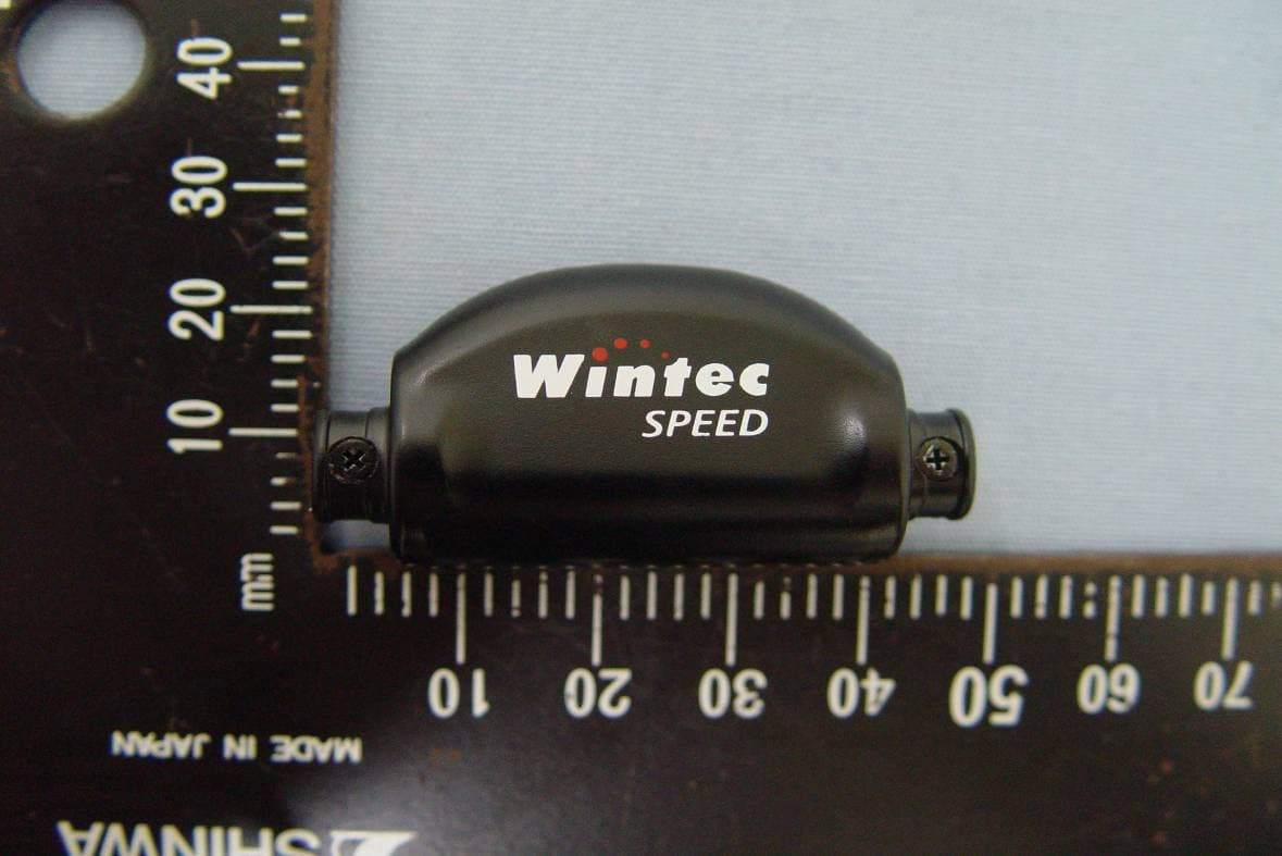
NJQCA04
Dec 24, 20112.4GHz ANT+ Wireless Bike Computer
Equipment Class
DXX - Part 15 Low Power Communication Device Transmitter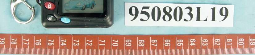
NJQ372HAF
Aug 30, 2006372.5MHz Wireless Remote Controller Transceiver
Equipment Class
DSR - Part 15 Remote Control/Security Device Transceiver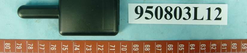
NJQ372BFA
Aug 30, 2006372.5MHz Wireless Remote Controller Transceiver
Equipment Class
DSR - Part 15 Remote Control/Security Device Transceiver
NJQWBT100
Dec 21, 2005Bluetooth GPS
Equipment Class
DSS - Part 15 Spread Spectrum Transmitter
NJQLP-4502
Jul 21, 2004FRS/GMRS UHF Transceiver
Equipment Class
FRF - Part 95 Family Radio Face Held Transmitter