NJQTR67BCar Alarm System Transceiver
Wintecronics Ltd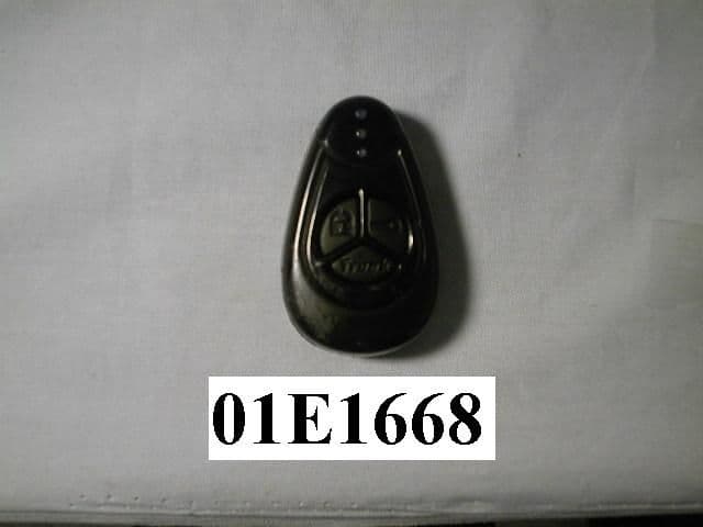
Click to zoom
Application Details
- Equipment Class
- DSR - Part 15 Remote Control/Security Device Transceiver
- Date of Grant
- Dec 17, 2001
- Application Purpose
- Original Equipment
- Date of Application
- Dec 17, 2001
- Equipment Note
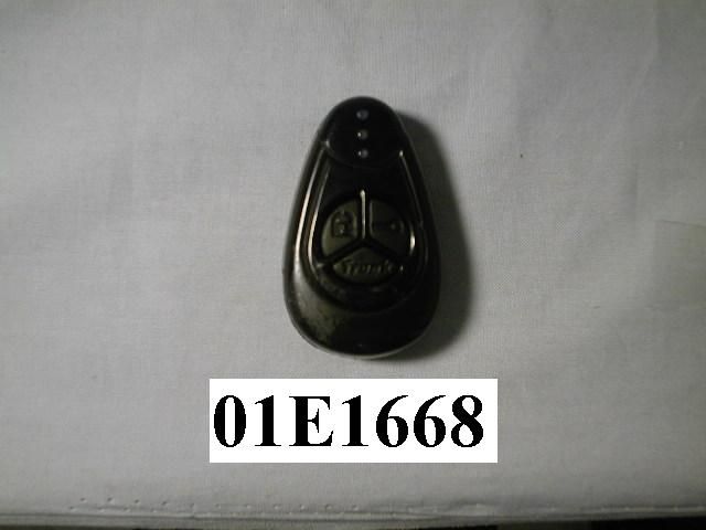
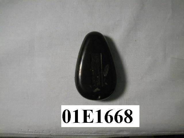
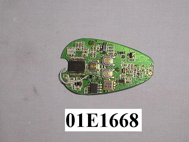
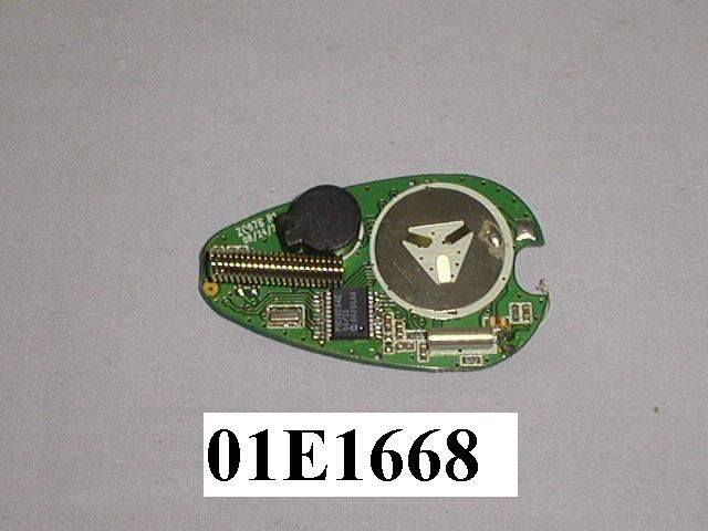
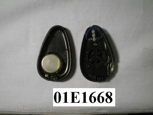
- Car Alarm System Transceiver
- Frequency Range
- 433.92000000 - 433.92000000
- Company
- Wintecronics Ltd
- Country
- Taiwan
Documents & Files
Document Text
Text extracted from the exhibit documents filed with the FCC. Open a document above to read the original.
Users Manual
1. For safety sake, check first if your ignition key can activate engine start while the hand gear is engaged. If engine starting can be done if hand gear is engaged, set gear mode in “manual hand gear mode” during installation (Refer to the operation guide.) 2. Check if immobilization feature is present in your automobile. If so, another accessory (Item no: 444) is required to enable remote engine start. This accessory can be bought from the same dealer. 3. Check the circuits and their current first. Refer to [Installation diagram for input/ output current values]. If the output current is lower than the requirement, additional relays must be added.] check the following after installation of alarm system 1. Installation is abnormal if the remote engine start can be done under these conditions (a) the gear is engaged 9b) ignition key is in “ Ignition ON Mode” (c) the engine hood is open (D) the hand brake is not engaged. 2. The remote control should control operation of function is the same way as the original key .If remote control can hardly remote engine start, the installation is abnormal. Check the related circuit connection of the ignition cylinder. 3. For servicing, repair and valet parking, “Valet mode” must be set to “ON”. Remote control features 1. Remote door lock/arm To remote door lock, press and release button after closing the door;: siren chirps once with one parking light flash. l The remote transmitter sound 1 buzz and its LCD display locked icon. It remote transmitter sound 4 buzzes , the system is not working normally. 2. Remote door unlock/disarm To remote the locked door, press and release; siren chirps twice with 2 parking light flashes . l The remote transmitter sounds 2 buzzes and its LCD show unlock icon 2 stages door unlock /disarm Refer to #36, Program table 1 Another accessory [1xxx] buyable from the same dealer is required .After setting the system at 2 stage door unlock, a press on buttoncan unlock driver’s door and longer press on the same button can unlock all other others. Siren chirps 2 times with 2 parking light flashes. l The remote transmitter sounds 2 buzzes and its LCD shows unlock icon Single Option (Choose One only) Activate channel # 3Refer to # 36, Features program table 1 The system must be set at Channel # 3 mode. Press and hold .The system responds according to its mode setting with 3 parking light flashes. l The remote transmitter sounds 3 buzzes and its LCD shows unlock icon 3. Security diagnostic report If there is \unlock/ disarm command received by the main system under lock/ arm mode; the main system will still remain in the arm mode. If any intrusion is attempted, the siren will chirps 4 times with 4 parking light flashes. The remote transmitter sounds 4 buzzes and its LCD will display the attempted zones. 4. Remote engine start To remote engine start while the ignition “OFF”, press and release ; siren chirps 3 times with 3 parking light flashes. During starting process, the remote transmitter sounds melody and its LCD show starting process, current status of the car. l The remote transmitter sounds melody with its LCD showing engine runs status. For runtime setup, refer to Program table at #36. Engine run shuts off when the preset time expires. If the engine start fails, the remote transmitter’s buzzer sounds 4 beeps twice. 5. Remote activate engine run timeRefer to Remote transmitter’s functions table Following the success of the engine start, each time press on can automatically extend engine runtime with 5 min step-up time. Maximum 20 min runtime can be attained. Engine shuts off PRE-INSTALLATION CHECK Model No. TR67B SUPER RANGE 2-WAY SECURITY WITH REMOTE ENGINE START automatically when the runtime expires. 6. Remote engine shut off To remote stop engine running, press and hold ,can engine will shut off with 2 confirming siren chirps and 2 parking light flashes. l The remote transmitter sounds melody with its LCD showing engine shutoff icon and current status. 7. Remote temperature-controlled start “ON/OFF” Refer to Features Program table at #36, 37or Remote transmitter’s functions table To turn “ON” this remote temperature-controlled start feature, press and hold both simultaneously . Siren chirps 3 times with 3 parking light flashes. [Refer to #36 for temperature setting]. When the pre-set temperature is reached, the engine start automatically l The remote transmitter sounds melody with LCD showing temp-start icon. To turn this feature “OFF” To turn this feature “OFF”, press bothsimultaneously. The remote transmitter sounds melody but its LCD does not show tem-start icon. 8. Programmed daily start-time “ON/OFF” Refer to Features program table at # 37 Press and hole bothsimultaneously at the desired time of the day to make the engine automatically start at the same time beginning the next day. Siren chirps 6 times with 6 parking light flashes. Press and release bothto deactivate this function. l The remote transmitter sounds melody with its LCD showing daily start-time icon “ON” and this features standby mode .Engine begins running immediately in this mode.For runtime setup, refer to Program table at # 36. Engine run shuts off when preset time expires. When the Engine start is done, the remote transmitter sounds melody with its LCD showing current status modes. 9. Status Check Press button to monitor the latest vehicle status. The parking light flashes 3 times, l The remote transmitter sounds melody and its LCD showing vehicle’s status. 10. Activate channel # 1 release trunk Press and hold to release trunk regardless of either lock/arm or unlock/disarm mode. Trunk is released with 3 parking light flashes and siren chirps 3 times. l The remote transmitter sounds melody showing the trunk release icon and the car’s status. 11. Remote siren /horn ON/OFF Refer to Features program table at # 36 or Remote transmitter’s features table Press and release to select between siren “ ON” and “OFF”. l The remote transmitter’s LCD shows siren a…
Text truncated - open the document above for the full version.
Block Diagram
zQ67ar1-BLK.sch-1 - Tue Oct 30 13:39:36 2001
Cover Letter(s)
From: NEUTRON_PChome [[email protected]] Sent: Monday, December 03, 2001 10:07 PM To: [email protected] Subject: from : NEUTRON ENGINEERING INC This FCC ID : "NJQTR67B" ASSESSMENT NUMBER IS : ANO1T1665 The above your Question 1~11 Q1: Above schematic diagram. I resent two files that you need for this application.(TR67B)Schematic Diagram.(PDF.files)and(TR67B)Block Diagram(PDF.files) Q2: Above External Phots and Internal Phots. I resent two files that you need for this applcation.(TR67B)External Phots, (TR67B)Internal Phots(JPG.files) Q3: Above EUT is a stand-alone unit, shall be placed in the center of the tabletop, I resent One files that you need for this application.(TR67B)Test Report(PDF.files)Please refer to the attachment. Q4: Same as Q3, Please refer to the attachment. Q5: Please refer to the Test Report, Includ test data above Peak Value and VGA Value. Q6: Please refer to the Test Report, Includ Duty cycle measurements. Q7: Please refer to the Test Report, Includ instrument setting for below 1GHz measurements. Q8: Above Operational description, I resent on files that you need for this application.(TR67B)Operational Description(PDF.files). Q9: Above (in case of FCC Doc procedures is used), the receiver model name. no same as TX. Which is complicased FCC Doc produce by "Neutron". Q10 : Above Page 7 of Test Report, Remark # 4 it should be 15.209. Please refer to the Test Report. Q11 : Above There is no such thing as Class A or Class B limits for unintentional Radiator(Receiver), I resent two files that you need for this application.(TR67B)User Nanual(PDF.files) and (TR67B)ID Lable Photo. THANK YOU VERY MUCH Sincerely, if you have any questions feel free to contact us [email protected]
ID Label/Location Info
NEUTRON EMC LAB. FCC ID: NJQTR67B 5/25 2. Product Labeling 2-1. FCC ID Label The remained portion of label statement required by FCC is attached in the user’s manual. 2-2 Location of Label on EUT FCC ID : NJQTR67B 0.8cm 2.5cm 01E1668
Operational Description
The Wintercronics Co., Ltd. Model: TR67B (referred to as the EUT in this report) is a Transceiver of car alarm security system. It offers wireless remote control, ideal for use in vehicle security system to activate the function of center door lock control system and car searching except the alarm system. A major technical descriptions of EUT is described as following: A). Fundamental Frequency: 433.92 MHz B). Modulation : Pulse Modulation C). Antenna Designation: Non-User Replaceable (Fixed) D). Power Supply: 3.0V, Battery Operated E). Receiver type : Superheterodyne ’ ≤
Schematics
ZQ67BR3(FCC).sch-1 - Tue Oct 30 08:55:19 2001
Test Report
NEUTRON EMC LAB. FCC ID: NJQTR67B 1/25 MEASUREMENT/TECHNICAL REPORT APPLICTNT:Wintercronics Co., Ltd. MODEL NO.:TR67B FCC ID:NJQTR67B This report concerns ( check one ) : Original Grant 3 Class II Change Equipment type: 433.92 MHz Remote Controller (Transmitter) Deferred grant requested per 47CFR 0.457(d)(1)(ii)? Yes No 3 If yes, defer until: (date) We, the undersigned, agree to notify the Commission by (date) / / of the intended date of announce meant of the product so that the grant can be issued on that date. Transition Rules Request per 15.37? Yes No 3 If no, assumed Part 15, Subpart B for unintentional radiator the new 47 CFR (10-1-90 Edition) provision. Report Prepared by Testing House Neutron Engineering Inc. for Company Name Wintercronics Co., Ltd. Address 2F., No. 7-1, Ming Lee Street, Chung Ho, Taipei, Taiwan, R.O.C. Applicant Signature Apin Chang / General Manager NEUTRON EMC LAB. FCC ID: NJQTR67B 2/25 CERTIFICATION We hereby certify that: The test data, data evaluation , test procedures, and equipment configurations shown in this report were made in accordance with the procedures given in ANSI C63.4 (1992) and the energy emitted by the sample EUT tested as described in this report is in compliance with conducted and radiated emission limits of FCC Rules Part 15. Prepared by Carol Chen Reviewed by Vincent Su Approved by George Yao Issued Date Oct. 30, 2001 Report No. NEI-FCCB-01182 Company Stamp NEUTRON ENGINEERING INC. No. 132-1, Lane 329, Sec. 2, Palain Rd., Shijr Jen, Taipei, Taiwan TEL: (02) 2646-5426 FAX : (02) 2646-6815 NEUTRON EMC LAB. FCC ID: NJQTR67B 3/25 Table of Contents 1.General Information...................................................................................................................... 1-1 Product Description................................................................................................................4 1-2 Related Submittal(s)/Grant(s)..................................................................................................4 1-3 Test Methodology.............................................................................................................4 1-4 Test Facility...................................................................................................................4 2.Product Labeling............................................................................................................................ Figure 2-1 FCC ID Label...............................................................................................................5 Figure 2-2 Location of Label on EUT............................................................................................5 3.System Test Configuration............................................................................................................. 3-1 EUT Configuration...................................................................................................................6 3-2 EUT Exercise............................................................................................................................6 3-3 Test Procedure..........................................................................................................................6 3-4 Limitation..................................................................................................................................7 3-5 Special Accessories...................................................................................................................7 3-6 Equipment Modifications...........................................................................................................7 3-7 Test Set-UP...............................................................................................................................8 3-8 Test Equipment........................................................................................................................9 4.Block Diagram(s)..............................................................................................................................10 5.Radiated Measurement Photos............................................................................ Figure 5-1. Radiated Emission Data...................................................................................11 6.Radiated Emission Data............................................................................................................ 6-1 Radiated Emission Data...........................................................................................................12 6-2 Field Strength Calculation.......................................................................................................18 6-3 Duty Cycle Correction Factor Calculated .............................................................................19 6-4 Correction Factor Table VS Frequency....................................................................................20 7.Supplementary Information for Section 15.231(C) Requirement .............................................21 8.Attachment...................................................................................................................................... A. Technical Information of Pulse Code Definition & Timing Chart ................................................22 B. Photos of Tested EUT...................................................................................................................24 C. User Manual..................................................................................................................................25 NEUTRON EMC LAB. FCC ID: NJQTR67B 4/25 1. GENERAL INFORMATION 1-1. Product Description The Wintercronics Co., Ltd. Model: TR67B (referred to as the EUT in this report) is a Tran- sceiver of car alarm security system. It offers wireless remote control, ideal for use in vehicle security system to activate the function of center door lock cont…
Text truncated - open the document above for the full version.
Test Setup Photos
NEUTRON EMC LAB. FCC ID: NJQTR67B 11/25 5. Radiated Measurement Photos NEUTRON EMC LAB. FCC ID: NJQTR67B 11-1/25 5. Radiated Measurement Photos
Contact Information
Applicant
Chang Chen Ping(Manager)
Test Firm
BTL Inc.Andy Chiu
Technical Specifications
| # | Rule Parts | Frequency Range | Power Output |
|---|---|---|---|
| 1 | 15C | 433.92 MHz - 433.92 MHz | - |
Other Applications from Wintecronics Ltd
NJQCA04
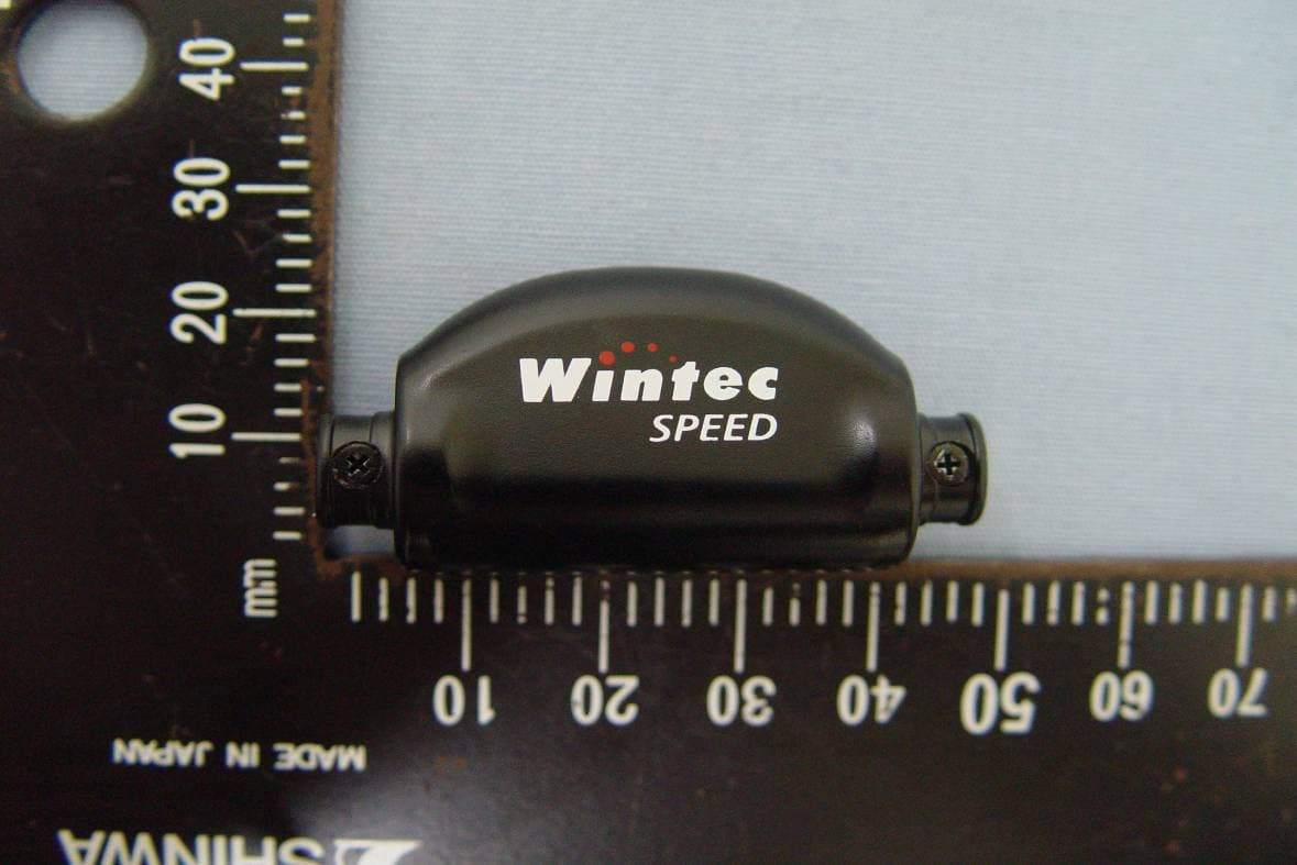
Dec 24, 20112.4GHz ANT+ Wireless Bike Computer
Equipment Class
DXX - Part 15 Low Power Communication Device Transmitter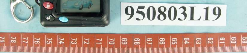
NJQ372HAF
Aug 30, 2006372.5MHz Wireless Remote Controller Transceiver
Equipment Class
DSR - Part 15 Remote Control/Security Device Transceiver
NJQ372BFA
Aug 30, 2006372.5MHz Wireless Remote Controller Transceiver
Equipment Class
DSR - Part 15 Remote Control/Security Device Transceiver
NJQWBT100
Dec 21, 2005Bluetooth GPS
Equipment Class
DSS - Part 15 Spread Spectrum Transmitter
NJQLP-4502
Jul 21, 2004FRS/GMRS UHF Transceiver
Equipment Class
FRF - Part 95 Family Radio Face Held Transmitter