NJQTR68BRemote Control Car Alarm Transceiver
Wintecronics Ltd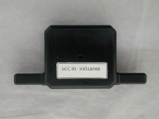
Click to zoom
Application Details
- Equipment Class
- DSR - Part 15 Remote Control/Security Device Transceiver
- Date of Grant
- May 21, 2002
- Application Purpose
- Original Equipment
- Date of Application
- May 21, 2002
- Equipment Note
- Remote Control Car Alarm Transceiver
- Frequency Range
- 433.92000000 - 433.92000000
- Company
- Wintecronics Ltd
- Country
- Taiwan
Documents & Files
Document Text
Text extracted from the exhibit documents filed with the FCC. Open a document above to read the original.
Users Manual
1 Model No. : L-TR68B 1. The L-TR68B is a 2-way security system featured with remote engine start and can be installed to work with any vehicle with its normal voltage of 12 volt. 2. The L-TR68B’s circuit is designed to suit both the manual gear and the auto-transmission gear car for remote engine starting. 3. The L-TR68B has 2 different engine start time circuit for remote starting of both gasoline engine and diesel engine. Installation of the major components Choice of place for main control module Install this behind the dashboard at the suitable position, near the ignition cylinder (within 60 cm from it) but far from the heat source and water tank. l Siren Choose its location in the engine compartment [far from the heat source and water tank, and free from the engine’s moving parts]. Drill a hole of 1/8 in drill at the selected place and secure the siren using the mounting bracket, facing the siren downward or in the horizontal position. l Hood switch While in arm mode or remote engine running, this helps the main control module detect the hood’s status .It must be installed on the grounded metal surface. Drill a hole of 1/4 inch at the selected place and secure the hood switch and adjust it. [The switch must have negative output when the hood is opened, and becomes neutral when the hood is closed.] Dash LED Status indicator During the security standby mode, this performs as a visual indicator against attempted theft and also is the current status indicator of the system. During programming of system features, the LED’s flashing pattern provides feedback as a confirmation for different active modes being achieved. Mount the LED at a suitable area to ensure better visibility either from inside or outside of the vehicle. Override switch System’s programming can be done using override switch as in the manual entry into valet mode, manual arm/disarm. It may not require concealment because the main system itself has other multi-security features. Then connect it with the system’s modules for valet switch. 2 RF transmitter module/ call button This is integral part of the main system for transmitting / receiving and paging by push button. Select its mounting place to insure the best transmission range. It is suggested to fix it on the left or right upper area of the interior side of the windshield, using the double stick tape included. Be sure not to block driver’s view. Anti –carjack switch While ignition “ON”, entry and exit of anti-carjack mode can be done by this switch. Select the mounting place within reach of the driver but must be a concealed place Drill a 5/32 inch hole for mounting it. Connect one end of its wire to the system’s negative and the other to the anti- carjack wire from the main system. [This wire gets negative input to make the main system to enter anti-carjack mode] Shock sensor While in arm mode, this helps the main system detects impacts upon the vehicle. It must be fixed onto the chassis or stable metal surface.[ keeping far from heat source , water tank and vehicle’s transmitter module ] .Adjust it for the optimal sensitivity. While in arm mod twist the adjustment pole to the (+) direction to make it more sensitive and to the (-) direction for lesser sensitivity. [Strike with your palms or shake the vehicle’s body and observe if the LED turns on in green color during light impact and it turns on in red color during heavy impact.] Wire installation guide This is the 2-way security system with remote engine start features. While the system is action, L-TR68B’s circuit interaction during remote controlling is the same situation with an ignition key. As the starter circuit differs depending on the car manufacturers, the main system’s circuit must be verified before wiring. THE 6 PIN MAIN POWER HARNESS WIRE: 1. Black/yellow trace wire: Connect this to the wire from the start motor wire Firstly locate the ignition switch wire which shows +12V when the ignition switch is turned to “Start position” . Cut this wire as in below illustration. Then connect the black/yellow trace wire 3 with wire from the start motor. The installing details are as below This kind of connection will enable the start kill during alarm trigger. 2. Blue wire: output connecting wire for ACC This provides the current needed by ACC. Locate the wire of the ignition switch area that shows (+) 12 v when the ignition key is turned to “ACC” and “ ignition” position . Connect this wire with the blue wire. But this wire must be “0” volts when the ignition key is turned to “ start” position. 3. Black/white wire: Connect this wire from the ignition key switch start motor wire Firstly locate the ignition switch wire which shows +12V when the ignition switch is turned to “Start position” . Cut this wire and connect the black/white trace wire with the wire from wire of the ignition switch. Refer to the above illustration. 4. Red wire: + 12 v power source # 1 Locate the 12v wire of the ignition switch and connect it with this. This supplies (+) 12V power with over 40 amps current ,regardless of position of the ignition key . This supplies power source for ACC, ignition # 1 , ignition # 2 , start wires and their relays. 5. Yellow wire: output connecting wire for ignition # 1 This provides the current required for the running of engine. Locate the wire of the ignition switch area that shows (+) 12 v when the ignition key is turned to “ignition” and “start” position. Connect this wire with the yellow wire. 4 6. Green wire: output connecting wire for ignition # 2 Locate the wire of the ignition switch area that shows (+) 12 v when the ignition key is turned to “ ignition” and “start” . Connect this wire with the green wire. NoteIn some vehicles, this wire shows “0” volts while the engine is starting or cranking. But in some vehicles, this provides +12 v current. Program this as required. [ Refer to RF Features Program Table 1, line 7th ] l THE 18 PIN INPUT/OUTPUT HARNESS WIRE 1. Red wire: system power 12 V (+) 15 A …
Text truncated - open the document above for the full version.
Block Diagram
zk68B-BLK.sch-1 - Wed Mar 20 18:13:39 2002
External Photos
Photo # 1. Front View Rear View
ID Label/Location Info
NEUTRON EMC LAB. FCC ID: NJQTR68B 5/21 2. Product Labeling 2-1. FCC ID Label The remained portion of label statement required by FCC is attached in the user’s manual. 2-2 Location of Label on EUT 1 cm 3.2 cm FCC ID : NJQTR68B
Internal Photos
Photo # 2 Unit partially Disassembled Photo # 3 Unit partially Disassembled Photo # 4 Unit partially Disassembled
Schematics
ZQ68bR2(FCC).sch-1 - Wed Mar 20 17:25:59 2002
Test Report
NEUTRON EMC LAB. FCC ID: NJQTR68B 1/21 MEASUREMENT/TECHNICAL REPORT APPLICTNT:Wintercronics Co., Ltd. MODEL NO.:L-TR68B FCC ID:NJQTR68B This report concerns ( check one ) : Original Grant 3 Class II Change Equipment type: 433.92 MHz Remote Controller (Transceiver) Deferred grant requested per 47CFR 0.457(d)(1)(ii)? Yes No 3 If yes, defer until: (date) We, the undersigned, agree to notify the Commission by (date) / / of the intended date of announce meant of the product so that the grant can be issued on that date. Transition Rules Request per 15.37? Yes No 3 If no, assumed Part 15, Subpart B for unintentional radiator the new 47 CFR (10-1-90 Edition) provision. Report Prepared by Testing House Neutron Engineering Inc. for Company Name Wintercronics Co., Ltd. Address 2F., No. 7-1, Ming Lee Street, Chung Ho, Taipei, Taiwan, R.O.C. Applicant Signature Apin Chang / General Manager NEUTRON EMC LAB. FCC ID: NJQTR68B 2/21 CERTIFICATION We hereby certify that: The test data , data evaluation , test procedures, and equipment configurations shown in this report were made in accordance with the procedures given in ANSI C63.4 (1992) and the energy emitted by the sample EUT tested as described in this report is in compliance with conducted and radiated emission limits of FCC Rules Part 15. Prepared by Carol Chen Reviewed by Vincent Su Approved by George Yao Issued Date Apr. 17, 2002 Report No. NEI-FCCB-02070 Company Stamp NEUTRON ENGINEERING INC. No. 132-1, Lane 329, Sec. 2, Palain Rd., Shijr Jen, Taipei, Taiwan TEL: (02) 2646-5426 FAX : (02) 2646-6815 NEUTRON EMC LAB. FCC ID: NJQTR68B 3/21 Table of Contents 1.General Information...................................................................................................................... 1-1 Product Description................................................................................................................4 1-2 Related Submittal(s)/Grant(s)..................................................................................................4 1-3 Test Methodology.............................................................................................................4 1-4 Test Facility...................................................................................................................4 2.Product Labeling............................................................................................................................ Figure 2-1 FCC ID Label...............................................................................................................5 Figure 2-2 Location of Label on EUT............................................................................................5 3.System Test Configuration............................................................................................................. 3-1 EUT Configuration...................................................................................................................6 3-2 EUT Exercise............................................................................................................................6 3-3 Test Procedure..........................................................................................................................6 3-4 Limitation..................................................................................................................................7 3-5 Special Accessories...................................................................................................................7 3-6 Equipment Modifications...........................................................................................................7 3-7 Test Set-UP...............................................................................................................................8 3-8 Test Equipment........................................................................................................................9 4.Block Diagram(s)..............................................................................................................................10 5.Radiated Measurement Photos............................................................................ Figure 5-1. Radiated Emission Data...................................................................................11 6.Radiated Emission Data............................................................................................................ 6-1 Radiated Emission Data...........................................................................................................12 6-2 Field Strength Calculation.......................................................................................................16 6-3 Duty Cycle Correction Factor Calculated .............................................................................17 7.Supplementary Information for Section 15.231(C) Requirement .............................................18 8.Attachment...................................................................................................................................... A. Technical Information of Pulse Code Definition & Timing Chart ................................................19 B. Photos of Tested EUT...................................................................................................................20 C. User Manual..................................................................................................................................21 NEUTRON EMC LAB. FCC ID: NJQTR68B 4/21 1. GENERAL INFORMATION 1-1. Product Description The Wintercronics Co., Ltd. Model: L-TR68B (referred to as the EUT in this report) is a Transceiver of car alarm security system. It offers wireless remote control, ideal for use in vehicle security system to activate the function of center door lock control system and car searching except the alarm system. A major technical descriptions of EUT is described as following: A). F…
Text truncated - open the document above for the full version.
Test Setup Photos
NEUTRON EMC LAB. FCC ID: NJQTR68B 11/21 5. Radiated Measurement Photos
Contact Information
Applicant
Chang Chen Ping(Manager)
Test Firm
BTL Inc.Andy Chiu
Technical Specifications
| # | Rule Parts | Frequency Range | Power Output |
|---|---|---|---|
| 1 | 15C | 433.92 MHz - 433.92 MHz | - |
Other Applications from Wintecronics Ltd
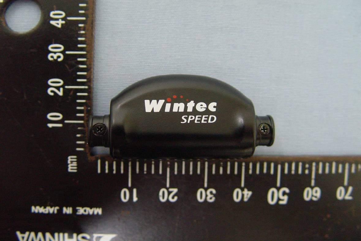
NJQCA04
Dec 24, 20112.4GHz ANT+ Wireless Bike Computer
Equipment Class
DXX - Part 15 Low Power Communication Device Transmitter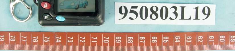
NJQ372HAF
Aug 30, 2006372.5MHz Wireless Remote Controller Transceiver
Equipment Class
DSR - Part 15 Remote Control/Security Device Transceiver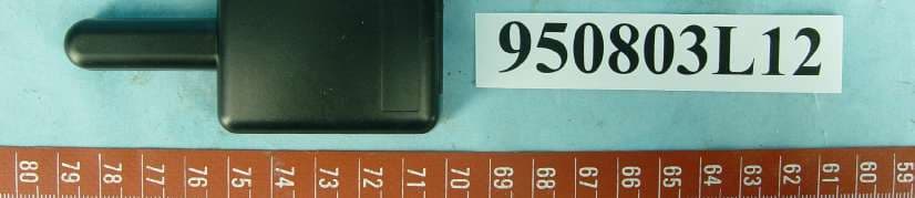
NJQ372BFA
Aug 30, 2006372.5MHz Wireless Remote Controller Transceiver
Equipment Class
DSR - Part 15 Remote Control/Security Device Transceiver
NJQWBT100
Dec 21, 2005Bluetooth GPS
Equipment Class
DSS - Part 15 Spread Spectrum Transmitter
NJQLP-4502
Jul 21, 2004FRS/GMRS UHF Transceiver
Equipment Class
FRF - Part 95 Family Radio Face Held Transmitter