NLB49012TX49 MHz TRANSMITTER
Dickie Toys Hong Kong Ltd.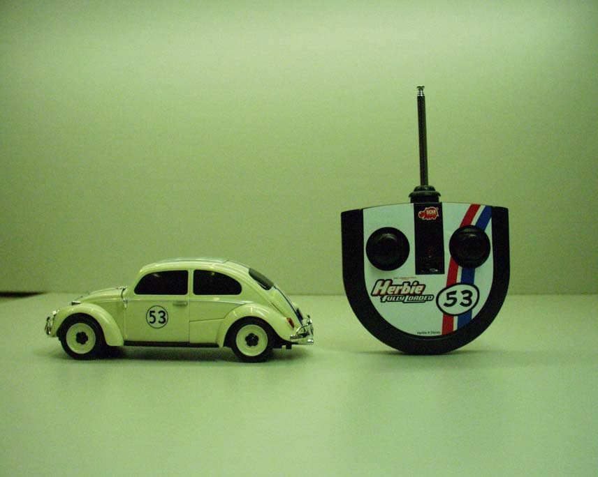
Click to zoom
Application Details
- Equipment Class
- DXX - Part 15 Low Power Communication Device Transmitter
- Date of Grant
- Nov 09, 2005
- Application Purpose
- Original Equipment
- Date of Application
- Nov 09, 2005
- Equipment Note
- 49 MHz TRANSMITTER
- Frequency Range
- 49.86000000 - 49.86000000
- Company
- Dickie Toys Hong Kong Ltd.
- Country
- Hong Kong
Documents & Files
Document Text
Text extracted from the exhibit documents filed with the FCC. Open a document above to read the original.
Users Manual
Art.-Nr. 308 9194 D: Bedienungsanleitung GB: Operating instructions F:Mode d’emploi I:Istruzioni per l’uso NL: Bedieningshandleiding E:Instrucciones de uso CZ:Návod k pouΩití H:Kezelési utasítás FIN: Käyttöohje S:Bruksanvisning DK: Betjeningsvejledning N: Betjeningsanvisning PL:Instrukcja u ̋ytkowania P:Instruções de utilização TR:Kullanım Talimatnamesi GR:∞Á·ËÙ¤ ÂÏ¿ÙË © Disney VW trademarks, design patents and copyrights are used with the approval of the Volkswagon AG. !! Nur Alkaline-Batterien oder wiederaufladbare NiMH-Batterien verwenden. Only alcaline-batteries or NiMH-batteries recommended. B A 2 3 1 L L R R 3 1 1x 9 V Block 6R 61 3 x 1,5 V R3 / UM-4 = 4,5 V oder / or / ou / o / of / nebo / vagy / tai / eller / eller / eller / albo / ou / yada / ‹ : 3 x 1,2 V = 3,6 V NiMH-Accus R 3 / UM-4 1, 5 V R 0 3 1,5 V UM-4 4 6 5 9 V Block 6R 61 9 V block (006P) 1, 5 V R 0 3 1,5 V UM-4 1, 5 V R 0 3 1,5 V UM-4 2 I II III C 4 3 2 1 2 1 1 2 3 1 1 2 3 1 2 1 2 3 D VORSICHT! 1. Niemals das Fahrzeug hochnehmen, solange die Räder noch drehen. 2. Finger, Haare und lose Kleidung nicht in die Nähe des Motors oder der Räder bringen, wenn das Gerät auf „ON“ geschaltet ist. 3. Um unvorhergesehenen Betrieb zu vermeiden, müssen die Batterien bei Nichtverwendung aus dem Spielzeug genommen werden. 4. Zuerst muss der Sender und dann das Fahrzeug eingeschaltet werden, um einen unvorhergesehenen Betrieb zu vermeiden. Beim Ausschalten stets das Fahrzeug und dann den Sender abschalten. La macchina non reagisce • Posizionare l’interruttore del trasmettitore e dell’auto su ON. • Le batterie o gli accumulatori sono inseriti correttamente? • I contatti delle batterie sono deformati o sporchi? • Le batterie o gli accumulatori sono scarichi o guasti? La maccina non reagisce correttamente il raggio d’azione è insufficiente • La potenza degli accumulatori o delle batterie è ridotta? • Nelle vicinanze sono presenti altri modellini con radiocomando a distanza che trasmettono alla stessa frequenza? • Recinsioni o reticolati metallici provocano interferenze? • I pali della luce o i piloni di trasmissione provocano spesso un comportamento incontrollato del modellino di automobile. • Nelle vicinanze sono presenti dei walkie-talkie o dei trasmettitori CB che possono provocare interferenze? I ATTENZIONE! 1. NON prendere in mano il veicolo quando é in movimento. 2. Tenere dita, capelli e indumenti lontani dalle ruote e dai semiassi delle ruote quando il veicolo é acceso (poisizione ”ON”). 3. Ad evitare accensioni accidentali, rimuovere le batterie quando non si utilizza il giocco. 4. Attenzione: accendere prima il trasmettitore e poi il veicolo al fine di evitare un azionamento imprevisto. Ricordarsi, una volta finito di giocare, di spegnere sempre prima il veicolo e poi il trasmettitore. Le véhicule ne réagit pas • Mettre les interrupteurs de l’emetteur et de l’auto sur ON. • Les batteries/accus sont-ils bien mis en place? • Les contacts de la batterie sont-ils tordus ou encrassés? • Les batteries/accus sont-ils déchargés ou défectueux? Le véhicule ne réagit pas correctement, la portée est trop faible • Les batteries/accus perdent en puissance? • D’autres maquettes dans le voisinage sont téléguidées á la même fréquence? • Des grillages/clôtures métalliques provoquent des perturbations? • Des émetteurs ou pylônes électriques peuvent pertuber le fonctionnement des maquettes. • Des talkies-walkies ou cibistes dans le voisinage peuvent entraîner des perturbations? F ATTENTION! 1. Ne pas saisir le véhicule en mouvement. 2. Lorsque le véhicule est EN MARCHE (position ON), ne pas mettre les doigts, ni laisser prendre des cheveux ou des vêtements à proximité des pneus et des moyeux de roue. 3. Pour éviter tout fonctionnement accidentel, il faudra enlever le bloc batterie lorsque le véhicule n‘est pas utilisé. 4. L’émetteur doit être mis en marche avant le véhicule pour éviter tout fonctionnement imprévu. Pour la mise hors circuit, le véhicule est toujours éteint en premier, l’émetteur en dernier. The model car is not responding to the signal • Switch remote control and model car to ON position. • Have batteries been correctly inserted? • Are the battery contacts bent or dirty? • Are batteries empty or faulty? The model car is not responding properly the remote control is out of range • Are the batteries losing strength? • Are there other radio controlled vehicles being used in the vicinity, maybe using the same frequency? • Are metal grids / fences causing disturbance? • Transmitting towers or pylons often interfere with the control of the models. • Are walkie-talkies / CB senders being used in the vicinity, maybe causing interference? GB ATTENTION! 1. Do not pick up vehicle while in motion. 2. Keep fingers, hair and loose clothing away from the tires and the wheel hub while the car is on. 3. To avoid accidental operation, remove battery pack when not in use. 4. First the receiver and then the car must be switched on to avoid an unexpected operation. Always switch off in reverse order, i.e. first the car and then the receiver. Das Fahrzeug reagiert nicht • Die Schalter vom Sender und Auto auf „ON“ stellen. • Sind Batterien/Akkus richtig eingelegt? • Sind die Batteriekontakte verbogen oder verschmutzt? • Sind Batterien entladen oder defekt? Das Fahrzeug reagiert nicht richtig, die Reichweite ist zu gering! • Läßt die Leistung der Batterien/Akkus nach? • Sind noch andere Modelle mit Funkfernsteuerung in der Nähe, die vielleicht auf der gleichen Frequenz senden? • Verursachen Metallgitter/Zäune Störungen? • Sende- oder Strommasten führen oft zu einem unkontrollierten Verhalten des Automodells. • Sind Walkie-Talkies/CB-Funker in der Nähe, die Störungen hervorrufen können? Specifiche • Radiocomando a 2 canali • 7 funzioni mobili: Avanti-sinistra-destra retromarchia-sinistra-destra-stop • Pezzi intercambiabili • Microregolazione dello sterzo • Disponibile in 2 frequenze Description • Radiotélécommande vitesse 2 canaux • 7 fonctions de pilotage…
Text truncated - open the document above for the full version.
External Photos
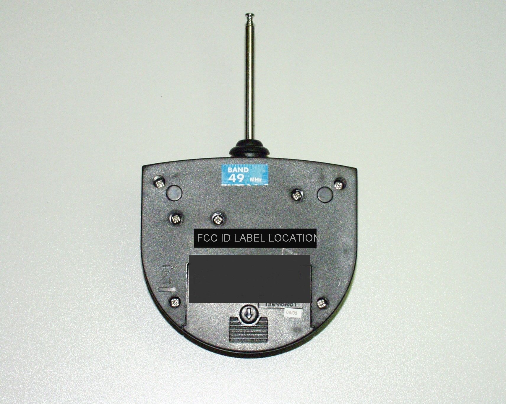
DICKIE- SPLIELZEUG GmbH & CO KG FCC ID: NLB49012TX EXTERNAL PHOTOS
ID Label/Location Info
Label for the US Transmitter Modul 49012 FCC ID: NLB49012TX Dickie Spielzeu GmbH Co. KG g Made in China This device complies with part 15 of the FCC rules Operation is subject to the following two conditions: (1)-This device may not cause harmful interference, and (2)-This device must accept any interference received, including interference that may cause undesired operation
Internal Photos
DICKIE- SPLIELZEUG GmbH & CO KG JOB # 2100UT5 INTERNAL PHOTOS
Operational Description
Dickie Spielzeug GmbH & Co. KG; Module 49012TX Circuit Description (With reference to Circuit Diagram and Blockdiagram) The circuit of module 49012TX is basically divided in four parts: 1. Oszillator (carrier frequency) 2. Modulation of signal 3. RF amplifier 4. Output circuit with antenna The Oszillator unit produces an carrier frequency of 49,860 MHz by using a quartz crystal, which is coupled via a transistor. The modulation is gained by an IC, beeing operated by the user trough the switches. Carrier and modulated signal are superposed at the base of a transistor, which amplifies the modulated carrier. The output circuit, beeing realised by capacitors and inductances matches the RF amplifier to the antenna providing RF-power being transfered to the antenna.
Test Report
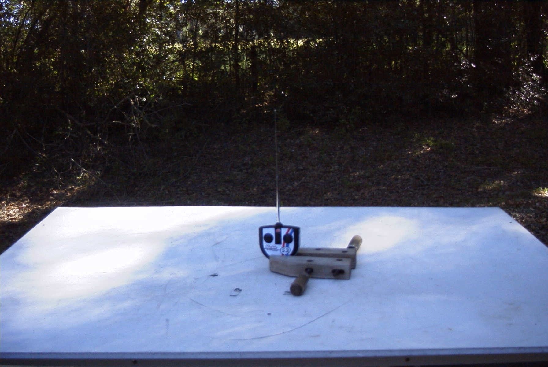
TIMCO ENGINEERING INC. 849 NW State Road 45 Newberry, Florida 32669 http://www.timcoengr.com 888.472.2424 F 352.472.2030 email: [email protected] APPLICANT: DICKIE-SPIELZEUG GmbH & CO KG Test Report Product Name: 49 MHz TRANSMITTER FCC ID: NLB49012TX Applicant: DICKIE-SPIELZEUG GmbH & CO KG WERKSTRABE 1 D-90765 FUERTH D-90765 GERMANY Date Receipt: 10/12/2005 Date Tested: 10/12/2005 FCC ID: NLB49012TX REPORT #: D\DICKIE\2099UT5\2099UT5TestReport.doc COVER SHEET TIMCO ENGINEERING INC. 849 NW State Road 45 Newberry, Florida 32669 http://www.timcoengr.com 888.472.2424 F 352.472.2030 email: [email protected] APPLICANT: DICKIE-SPIELZEUG GmbH & CO KG TABLE OF CONTENTS LIST APPLICANT: DICKIE-SPIELZEUG GmbH & CO KG FCC ID: NLB49012TX TEST REPORT CONTAINING: PAGE 1.............TEST EQUIPMENT LIST PAGE 2.............TEST PROCEDURE PAGE 3.............RADIATION INTERFERENCE TEST DATA PAGE 4.............OCCUPIED BANDWIDTH PAGE 5.............OCCUPIED BANDWIDTH PLOT EXHIBITS INCLUDING: BLOCK DIAGRAM SCHEMATIC INSTRUCTION MANUAL LABEL SAMPLE LABEL LOCATION EXTERNAL PHOTOGRAPHS INTERNAL PHOTOGRAPHS CIRCUIT DESCRIPTION TEST SET UP PHOTOGRAPH FCC ID: NLB49012TX REPORT #: D\DICKIE\2099UT5\2099UT5TestReport.doc TABLE OF CONTENTS TIMCO ENGINEERING INC. 849 NW State Road 45 Newberry, Florida 32669 http://www.timcoengr.com 888.472.2424 F 352.472.2030 email: [email protected] APPLICANT: DICKIE-SPIELZEUG GmbH & CO KG Equipment List Device Manufacturer Model Serial Number Cal/Char Date Due Date 3/10-Meter OATS TEI N/A N/A Listed 3/27/04 3/26/07 3-Meter OATS TEI N/A N/A Listed 1/13/03 1/12/06 Biconnical Antenna Eaton 94455-1 1057 CAL 3/18/03 3/18/05 Biconnical Antenna Eaton 94455-1 1096 CAL 8/17/04 8/17/06 Biconnical Antenna Electro- Metrics BIA-25 1171 CAL 4/29/05 4/29/07 Blue Tower Quasi-Peak Adapter HP 85650A 2811A01279 CAL 4/13/05 4/13/07 Blue Tower RF Preselector HP 85685A 2926A00983 CAL 8/3/05 8/3/07 Blue Tower Spectrum Analyzer HP 8568B 2928A04729 2848A18049 CAL 4/13/05 4/13/07 LISN Electro- Metrics ANS-25/2 2604 CAL 8/27/04 8/27/06 LISN Electro- Metrics EM-7820 2682 CAL 4/28/05 4/28/07 Log- Periodic Antenna Eaton 96005 1243 CAL 5/8/03 5/8/05 FCC ID: NLB49012TX REPORT #: D\DICKIE\2099UT5\2099UT5TestReport.doc Page 1 of 5 TIMCO ENGINEERING INC. 849 NW State Road 45 Newberry, Florida 32669 http://www.timcoengr.com 888.472.2424 F 352.472.2030 email: [email protected] APPLICANT: DICKIE-SPIELZEUG GmbH & CO KG TEST PROCEDURE GENERAL: This report shall NOT be reproduced except in full without the written approval of TIMCO ENGINEERING, INC. RADIATION INTERFERENCE: The test procedure used was ANSI STANDARD C63.4-2003 using a HEWLETT PACKARD spectrum analyzer with a pre-selector. The bandwidth of the spectrum analyzer was 100 kHz with an appropriate sweep speed. The analyzer was calibrated in dB above a microvolt at the output of the antenna. The resolution bandwidth was 100 kHz and the video bandwidth was 300 kHz. The ambient temperature of the UUT was 80ºC with a humidity of 76%. FORMULA OF CONVERSION FACTORS: The Field Strength at 3m was established by adding the meter reading of the spectrum analyzer (which is set to read in units of dBuV) to the antenna correction factor supplied by the antenna manufacturer. The antenna correction factors are stated in terms of dB. The gain of the Pre- selector was accounted for in the Spectrum Analyzer Meter Reading. Example: Freq (MHz) METER READING + ACF = FS 33 20 dBuV + 10.36 dB = 30.36 dBuV/m @ 3m ANSI STANDARD C63.4-2003 10.1.7 MEASUREMENT PROCEDURES: The unit under test was placed on a table 80 cm high and with dimensions of 1m by 1.5m. The table used for radiated measurements is capable of continuous rotation. When an emission was found, the table was rotated to produce the maximum signal strength. At this point, the antenna was raised and lowered from 1m to 4m. The antenna was placed in both the horizontal and vertical planes. FCC ID: NLB49012TX REPORT #: D\DICKIE\2099UT5\2099UT5TestReport.doc Page 2 of 5 TIMCO ENGINEERING INC. 849 NW State Road 45 Newberry, Florida 32669 http://www.timcoengr.com 888.472.2424 F 352.472.2030 email: [email protected] APPLICANT: DICKIE-SPIELZEUG GmbH & CO KG APPLICANT: DICKIE-SPIELZEUG GmbH & CO KG FCC ID: NLB49012TX NAME OF TEST: RADIATION INTERFERENCE RULES PART NO.: 15.235 REQUIREMENTS: CARRIER FREQUENCY WILL NOT EXCEEDS 80 dBuV/m AT 3M. OUT-OF-BAND EMISSIONS SHALL NOT EXCEED: 30 - 88 MHz 40.0 dBuV/M MEASURED AT 3 METERS 88 - 216 MHz 43.5 dBuV/M 216 - 960 MHz 46.0 dBuV/M ABOVE 960 MHz 54.0 dBuV/M TEST DATA: Tuned Frequency MHz Emission Frequency MHz Meter Reading dBuV Ant. Polarity Coax Loss dB Correction Factor dB Field Strength dBuV/m Margin dB 49.9 49.86 64.4 H 0.97 11.63 77.00 3.00 49.9 49.86 66.1 V 0.97 10.71 77.78 2.22 49.9 99.72 27.2 H 1.40 10.89 39.49 4.01 49.9 99.72 27.3 V 1.40 11.42 40.12 3.38 49.9 149.58 9.5 V 1.75 16.86 28.11 15.39 49.9 149.58 11.5 H 1.75 16.16 29.41 14.09 49.9 199.44 18.1 H 2.10 17.10 37.30 6.20 49.9 199.44 20.1 V 2.10 17.70 39.90 3.60 49.9 249.30 4.8 H 2.35 12.37 19.52 26.48 49.9 249.30 7.9 V 2.35 12.46 22.71 23.29 49.9 299.16 11.7 V 2.60 14.29 28.59 17.41 49.9 349.02 6.3 V 2.85 14.43 23.58 22.42 SAMPLE CALCULATION: FSdBuV/m = MR (dBuV) + ACFdB. TEST PROCEDURE: The procedure used was ANSI STANDARD C63.4-2003. The spectrum was scanned from 30 MHz to 1000 MHz. When an emission was found, the table was rotated to produce the maximum signal strength. The antenna was placed in both the horizontal and vertical planes and the worse case emissions were reported. The UUT was tested in 3 orthogonal planes. TEST RESULTS: THE UNIT DOES MEET THE FCC REQUIREMENTS. PERFORMED BY: MARIO R. de ARANZETA DATE: 10/12/2005 FCC ID: NLB49012TX REPORT #: D\DICKIE\2099UT5\2099UT5TestReport.doc Page 3 of 5 TIMCO ENGINEERING INC. 849 NW State Road 45 Newberry, Florida 32669 http://www.timcoengr.com 888.472.2424 F 352.472.2030 email: [email protected] APPLICANT: DICKIE-SPIELZEUG GmbH & CO KG APPLICANT: DICKIE-SPIELZEUG GmbH & CO KG FCC…
Text truncated - open the document above for the full version.
Contact Information
Applicant
Walter Wong(Quality Assurance Engineer)
Test Firm
Timco Engineering, Inc.S Sanders
Technical Specifications
| # | Rule Parts | Frequency Range | Power Output |
|---|---|---|---|
| 1 | 15C | 49.86 MHz - 49.86 MHz | - |
Other Applications from Dickie Toys Hong Kong Ltd.
NLB24067TX
Aug 25, 2021Short Range Device - Radio Controlled Toy Transmitter (2.4GHz)
Equipment Class
DXX - Part 15 Low Power Communication Device Transmitter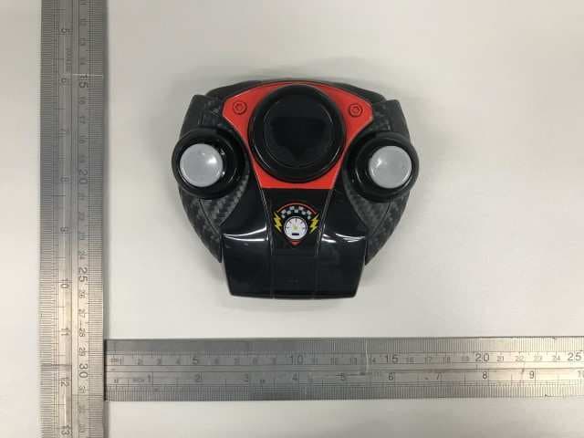
NLB24050TX
Sep 07, 2020Radio Controlled Toy Transmitter (2.4GHz)
Equipment Class
DXX - Part 15 Low Power Communication Device Transmitter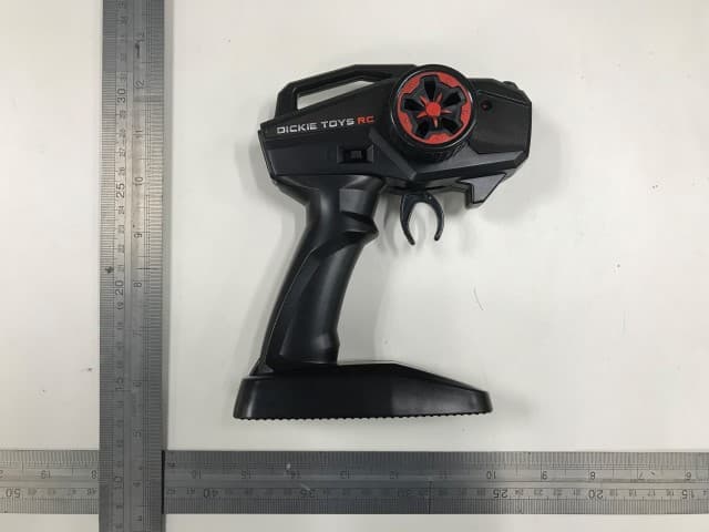
NLB24058TX
Jun 13, 2020Radio Controlled Toy Transmitter (2.4GHz)
Equipment Class
DXX - Part 15 Low Power Communication Device Transmitter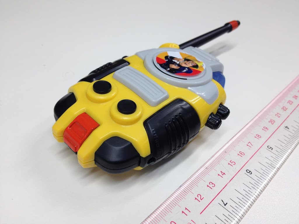
NLB27198TX
Sep 17, 2014Low Power Transmitter (27.145MHz)
Equipment Class
DXX - Part 15 Low Power Communication Device Transmitter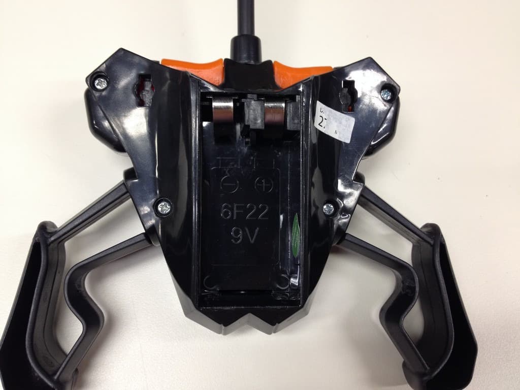
NLB27205TX
Sep 16, 2014Low Power Transmitter (27.145MHz)
Equipment Class
DXX - Part 15 Low Power Communication Device Transmitter