NLMIEYEPROUSB PC Camera
Hanwha Techwin Co., Ltd.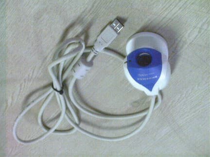
Click to zoom
Application Details
- Equipment Class
- JBP - Part 15 Class B Computing Device Peripheral
- Date of Grant
- Sep 07, 2000
- Application Purpose
- Original Equipment
- Date of Application
- Sep 07, 2000
- Equipment Note
- USB PC Camera
- Company
- Hanwha Techwin Co., Ltd.
- Country
- South Korea
Documents & Files
Document Text
Text extracted from the exhibit documents filed with the FCC. Open a document above to read the original.
Users Manual
- 1 - U U U S S S B B B P P P C C C C C C a a a m m m e e e r r r a a a I I I n n n s s s t t t a a a l l l l l l a a a t t t i i i o o o n n n G G G u u u i i i d d d e e e SAMSUNG AEROSPACE - 2 - FCC Compliance Statement This device complies with part 15 of the FCC Rules. Operation is subject to the follow ing tw o co nditions: (1) This device ma y no t cause har mful interference, and (2) this device must accept any interference received, including interference that may cause undesired operation. Note: This equipment has been tested and found to comply with the limits for a Class B digital device, pursuant to part 15 of the FCC Rules. These limits are designed to provide reasonable protection against harmful interference in a residential installation. This equipment generates, uses and can radiate radio frequency energy and, if not installed and used in accordance with the instructions, may cause harmful interference to radio communications. However, there is no guarantee that interference will not occur in a particular installation. If this equipment does cause harmful interference to radio or television reception, which can be determined by turning the equipment off and on, the user is encouraged to try to correct the interference by one or more of the following measures: - Reorient or relocate the receiving antenna. - Increase the separation between the equipment and receiver. - Connect the equipment into an outlet on a circuit different from that to which the receiver is connected. - Consult the dealer or an experienced radio/TV technician for help. Warning: You are cautioned that any change or modifications to the equipment not expressly approved by the party responsible for compliance could void your authority to operate such equipment. NOTE: This unit was tested with shielded cables on the peripheral devices. Shielded cables must be used with the unit to insure compliance. - 3 - S S S A A A M M M S S S U U U N N N G G G U U U S S S B B B P P P C C C C C C a a a m m m e e e r r r a a a I I I n n n s s s t t t a a a l l l l l l a a a t t t i i i o o o n n n G G G u u u i i i d d d e e e 1. Before the installation • Check your PC system if it is superior than the following Minimum System Requirements. In case of inferiority, it may cause the installation error or malfunction of the camera. •Minimum System Requirements - USB support Host PC - Pentium 200MHz MMX (233MHz MMX or faster recommended) - Windows 98/2000 - 32MB RAM (64MB recommended) - 100MB hard disk space available - CD-ROM drive - 800x600, 16 bit color display (1024x768 recommended) - Microsoft Internet Explorer for video e-mail - LAN card or 56.6K bps modem for Video Conference - Windows compatible sound card (full duplex sound card recommended) - Speakers required for receiving audio - Microphone required for sending audio • Power on the PC and start Windows. 2. Installing the software • Place the CD-ROM into your CD-ROM drive. The autoplay installation program will start automatically. - It takes 5~10 seconds to load the autoplay according to PC system. If the software does not automatically load, run “ Windows Explorer ” . And then run “ autoplay.exe ” in CD-ROM drive. ! Note : Install the software first before connecting the amera with P ! Note : Install the software first before connecting the amera with P - 4 - 1) Installing the Power View The autoplay will load the installation window, as shown in right picture. Press “ Power View ” and select “ English ” . Power View program will be Installed automatically and come back to the installation window. 2) Installing the Power Album and finishing the installation • Press “ Power Album ” and select “ English ” . • Click Next. • Click Next. - 5 - • After successful installation, the right window will appear. Click Finish and then the installation window will appear once again. • The software installation is finished completely. Find the finish mark ( • ) in the installation window and click “ Exit ” . 3. Connecting the camera with PC [ ] • Plug the USB cable of camera in USB port of PC. • “ Add New Hardware Wizard ” ! Note : Install the software first before connecting the camera with P - 6 - ENH-se05.jpg ENH-se03.jpg ENH-se04.jpg ENH-se02.jpg ENH-se05.jpg window will appear. Click Next to continue. • Click Next. • Find the mark ( • ) at “ Specify a location ” in Wizard window. And click Next. • Click Next. - 7 - ENH-se03.jpg ENH-se02.jpg ENH-se06.jpg • After successful installation, the right window will appear. Click Finish and then the indicator lamp of camera will turn on. Now you can work with USB PC Camera. …
Text truncated - open the document above for the full version.
Block Diagram
Image Sensor OV7620 USB Controller OV511+ DRAM USB PC D-D+ DC-DC 3.3V DC-DC 5V USB Power Image Sensor OV7620 USB Controller OV511+ DRAM USB PC Y[7:0]UV[7:0]CLK A[8:0] D[15:0] D+D- LED S/W X-tal CLK 48MHz SNAP
External Photos
Model : i eye pro Test Report No. : 00JAC009.FCC 2000 JungAng EMC Co., Ltd. FCC ID : NLMIEYEPRO Page 18 of 26 A1-1 External Photo of EUT(Top) A1-2 External Photo of EUT(Bottom)
ID Label/Location Info
Model : i eye pro Test Report No. : 00JAC009.FCC 2000 JungAng EMC Co., Ltd. FCC ID : NLMIEYEPRO Page 22 of 26 A2-1 Label Requirements A class B digital equipment subject to certification by the FCC shall carry a warning label which includes the following statements: This device complies with part 15 of the FCC Rules. Operation is subject to the following two conditions: (1) This device may not cause harmful interference, and (2) this device must accept any interference received, including interference that may cause undesired operation. This statement should be stuck in a conspicuous location on the device. If impossible, this warning label should be placed in a prominent location in the user’s manual. A2-2 ID Label Drawing Model No : i eye pro Serial No : xxxxxxx FCC ID: NLMIEYEPRO SAMSUNG AEROSPACE INDUSTRIES, LTD. Made in Korea A2-3 ID Label Location : Bottom side of EUT
Internal Photos
Model : i eye pro Test Report No. : 00JAC009.FCC 2000 JungAng EMC Co., Ltd. FCC ID : NLMIEYEPRO Page 19 of 26 A1-3 Internal Photo of EUT Model : i eye pro Test Report No. : 00JAC009.FCC 2000 JungAng EMC Co., Ltd. FCC ID : NLMIEYEPRO Page 20 of 26 A1-4 Internal Photo of EUT(PCB)
Test Report
Model : i eye pro Test Report No. : 00JAC009.FCC 2000 JungAng EMC Co., Ltd. FCC ID : NLMIEYEPRO Page 1 of 26 JungAng EMC Co., Ltd. 109-2, Yepyung-ri, Kumsa-myun, Youju-kun, Kyungki-do, KOREA TEL: 82 2 571 8217 FAX:82 31 764 0126 FCC EMI TEST REPORT Date of Test: August 10-11, 2000 Test Report No: 00JAC009.FCC Test Site: JungAng EMC Co., Ltd., Korea(31040/SIT 1300F2) Trade Name : N/A Manufacturer: SAMSUNG AEROSPACE INDUSTRIES, LTD. Address : 42, Sungju-Dong, Changwon-City, Kyungnam, Korea Contact Person: JAE WON JANG/Asst. Manager Tel No. : 82-551-260-5912 Fax No. : 82-551-260-5955 Product: USB PC Camera Model : i eye pro Fcc Rule Part(s) : FCC Part 15 Subpart B Classification: Class B The device bearing the trade name and model specified above has been shown to comply with the applicable technical standards as indicated in the measurement report and was tested in accordance with the measurement procedures specified in ANSI C.63.4-1992. I attest to the accuracy of data and all measurement reported herein were performed by me or were made under my supervision and are correct to the best of my knowledge and belief. I assume full responsibility for the completeness of these measurements and vouch for the qualification of all persons taking them. TaeHyun Nam President-JungAng EMC Co., Ltd. http://www.jaemc.co.kr TABLE OF CONTENTS PAGE Model : i eye pro Test Report No. : 00JAC009.FCC 2000 JungAng EMC Co., Ltd. FCC ID : NLMIEYEPRO Page 2 of 26 1. Description of device 3 1.1 General 3 1.2 EUT Description 3 2. Test facility 4 3. Summary of results 4 3.1 Electromagnetic Emission 4 3.2 Modifications to the EUT 4 4. Tested system details 5 4.1 Peripherals and Others 5 4.2 Type of Cables Used 5 4.3 System layout on EUT and peripherals 6 5. Test result 7 5.1 RFI Voltage Measurement 7 5.2 RFI Field Strength Measurement 11 5.3 Minimum Margin 13 5.4 Sample Calculations 13 6. Test Equipments 14 7. Measurement Photos15 7.1 Setup with RFI Voltage Emission Level 15 7.2 Setup with RFI Field Strength Emission Level 16 Appendix 1 Photos of EUT17 Appendix 2 ID Label and Location22 Appendix 3 System Block Diagram24 Appendix 4 User’s Manual26 1. DESCRIPTION OF DEVICE Model : i eye pro Test Report No. : 00JAC009.FCC 2000 JungAng EMC Co., Ltd. FCC ID : NLMIEYEPRO Page 3 of 26 1.1 General Responsible Party SAMSUNG AEROSPACE INDUSTRIES, LTD. Contact Person JAE WON JANG Tel No. : 82-551-260-5912 Fax No. : 82-551-260-5955 Manufacturer SAMSUNG AEROSPACE INDUSTRIES, LTD. 42, Sungju-Dong, Changwon-City, Kyungnam, Korea •Trade name SAMSUNG •Model name i eye pro •EUT Type USB PC Camera •Classification FCC Part 15 Subpart B Class B •Clock Speed Main Clock : 48MHz •Rule Part(s) FCC Part 15 & Part 2 •Test Procedure(s) ANSI C63.4(1992) • Date of TestsA ugust 10-11, 2000 •Place of Tests JungAng EMC Co., Ltd. 1.2 EUT Description The EUT is a small size of USB PC camera, can be used with various personal purpose such as viewing images, capturing still images and motion detection, video-conference call, creating sticky pictures, photo albums and greeting cards, and playing some games. ! !! ! Note. This report may be reproduced in full. Partial reproduction may only be made with the written permission of the laboratory. The results in this report is only applied to the sample(s) tested. ! !! ! Note. Please refer to the duties and responsibilities of the Responsible Party attached. Model : i eye pro Test Report No. : 00JAC009.FCC 2000 JungAng EMC Co., Ltd. FCC ID : NLMIEYEPRO Page 4 of 26 2. TEST FACILITY The open field test site and conducted measurement facility used for this measurement, is located following address. This site was fully described in a report dated Nov. 24, 1998, that was submitted to the FCC. Our site and facility had been accepted in a letter dated Nov. 24, 1998(31040/SIT) : JungAng EMC Co., Ltd. Address : 109-2, Yepyung-ri, Kumsa-myun, Youju-kun, Kyungki-do, Korea The detailed description of the measurement facility was found to be in compliance with the requirements of §2.948 according to ANSI C63.4 on October 19, 1992. 3. SUMMARY OF RESULTS 3.1 Electromagnetic Emission RFI Voltage Measurement............................... PASS RFI Field Strength Measurement........................ PASS Although the measured emissions indicate that the EUT complies with the required limits, some measurements are close to these limits. When the uncertainty of measurement is considered, there is some possibility that the EUT may not be compliant. 3.2 Modifications to the EUT : None Model : i eye pro Test Report No. : 00JAC009.FCC 2000 JungAng EMC Co., Ltd. FCC ID : NLMIEYEPRO Page 5 of 26 4. TESTED SYSTEM DETAILS 4.1 Peripherals and Others : DescriptionModel NameSerial No.ManufacturerFCC ID ComputerDESKPRO7836BVD20016CompaqDoC PrinterC2106A3217S91901HPB94C2106X MonitorVX700M902080938GatewayBGBTFV8705K KeyboardRT235BTWB13BC90L39GUCompaqAQ6-22K15 Mouse #1M-S34F13490N5BGFCompaqDZL211029 Mouse #2Pro Mouse II96002117NEOTECFSUGMZC7 4.2 Type of Cables Used: Device fromDevice toType of CableLengthType of shield ComputerMonitorSignal cable1.0shielded ComputerPrinterSignal cable1.8shielded ComputerKeyboardSignal cable2.0shielded ComputerMouse #1Signal cable1.5shielded ComputerMouse #2Signal cable1.5shielded Computer USB PC Camera Signal cable1.5shielded ComputerMain PowerPower cable1.5Non-shielded MonitorMain PowerPower cable1.5Non-shielded PrinterMain PowerPower cable1.5Non-shielded Model : i eye pro Test Report No. : 00JAC009.FCC 2000 JungAng EMC Co., Ltd. FCC ID : NLMIEYEPRO Page 6 of 26 4.3 System layout on EUT and peripherals EUT Figure 4-1 System layout Monitor Computer USB P C Camera KeyboardMouseMouse Printer Model : i eye pro Test Report No. : 00JAC009.FCC 2000 JungAng EMC Co., Ltd. FCC ID : NLMIEYEPRO Page 7 of 26 5. TEST RESULT 5.1 RFI Voltage Measurement 5.1.1 Measurement Instrumentation Used (model/serial no./manufacturer/last calibration/next calibration) Signal Analyzer............(PMM9000/3100J70602/PMM/08 Oct. 1999/…
Text truncated - open the document above for the full version.
Contact Information
Applicant
JEISOON KANG(Principal Research Engineer)
Test Firm
Jungang EMC Ltd.Tae Nam
Technical Specifications
| # | Rule Parts | Frequency Range | Power Output |
|---|---|---|---|
| 1 | 15B | - | - |
Other Applications from Hanwha Techwin Co., Ltd.
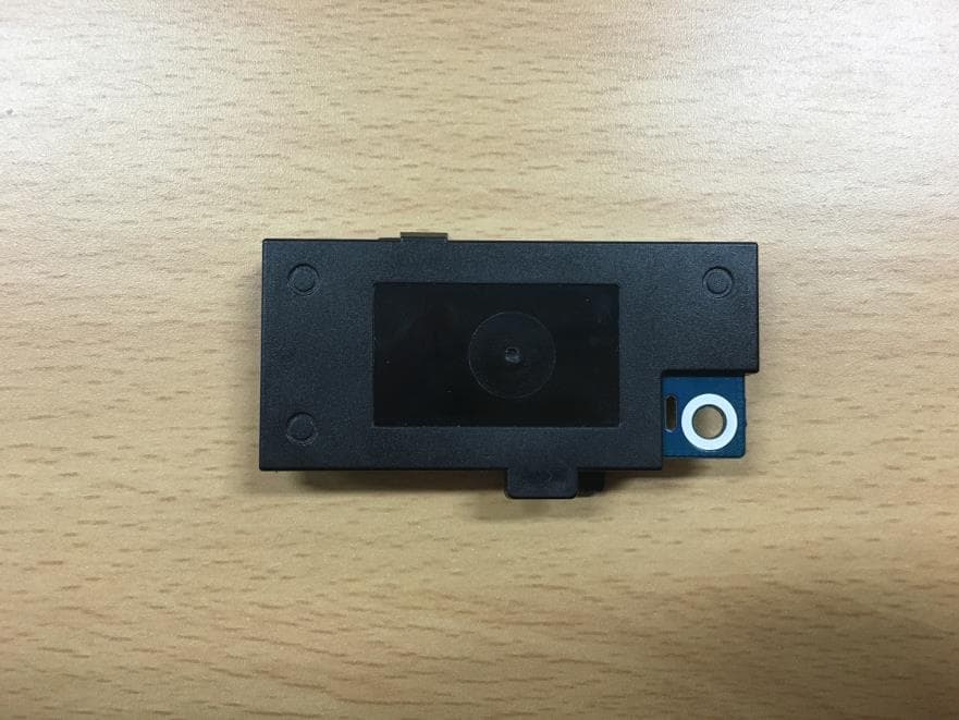
NLMSWLQ93T
Dec 22, 2015WiFi Module
Equipment Class
NII - Unlicensed National Information Infrastructure TX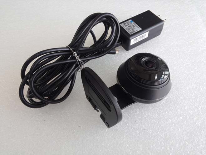
NLMSNHV6414BN
Nov 19, 2015SMART HOME CAMERA
Equipment Class
DTS - Digital Transmission System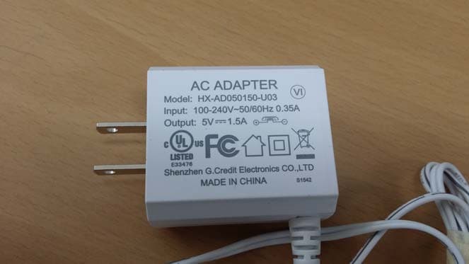
NLMSEP1003RWN
Nov 16, 2015Wireless Baby Camera
Equipment Class
DSS - Part 15 Spread Spectrum Transmitter
NLMSEW3043WN
Nov 16, 2015Wireless Baby Monitor
Equipment Class
DSS - Part 15 Spread Spectrum Transmitter
NLMSEW3036W
Jun 16, 2015Baby Monitor
Equipment Class
DSS - Part 15 Spread Spectrum Transmitter