NLMSEW-2000WWireless Receiver
Hanwha Techwin Co., Ltd.
Click to zoom
Application Details
- Equipment Class
- DSS - Part 15 Spread Spectrum Transmitter
- Date of Grant
- Mar 18, 2012
- Application Purpose
- Original Equipment
- Date of Application
- Mar 18, 2012
- Equipment Note
- Wireless Receiver
- Frequency Range
- 2402.00000000 - 2480.00000000
- Company
- Hanwha Techwin Co., Ltd.
- Country
- South Korea
Documents & Files
Document Text
Text extracted from the exhibit documents filed with the FCC. Open a document above to read the original.
Users Manual
http://www.emc2000.co.kr FCC RF TEST REPORT Report No.: EMC-FCC-R00 Appendix 6. User manual EMCcomplianceLtd. 480-5 Shin-dong, Yeongtong-gu, Suwon-city, Gyeonggi-do, 443-390, Korea 82 31 336 9919 (Main) 82 31 336 4767 (Fax) This test report shall not be reproduced except in full, Without the written approval. User Manual English IMPORTANT SAFETY INSTRUCTIONS 1. Read these instructions. 2. Keep these instructions. 3. Heed all warnings. 4. Follow all instructions. 5. Do not use this apparatus near water. 6. Clean only with dry cloth. 7. Do not block any ventilation openings, Install in accordance with the manufacturer’s instructions. 8. Do not install near any heat sources such as radiators, heat registers, stoves, or other apparatus (including amplifiers) that produce heat. 9. Do not defeat the safety purpose of the polarized or grounding-type plug. A polarized plug has two blades with one wider than the other. A grounding type plug has two blades and a third grounding prong. The wide blade or the third prong are provided for your safety. If the provided plug does not fit into your outlet, consult an electrician for replacement of the obsolete outlet. 10. Protect the power cord from being walked on or pinched particularly at plugs, convenience receptacles, and the point where they exit from the apparatus. 11. Only use attachments/ accessories specified by the manufacturer. 12. Use only with the cart, stand, tripod, bracket, or table specified by the manufacturer, or sold with the apparatus. When a cart is used, use caution when moving the cart/ apparatus combination to avoid injury from tip-over. 13. Unplug this apparatus during lighting storms or when unused for long periods of time. 14. Refer all servicing to qualified service personnel. Servicing is required when the apparatus has been damaged in any way, such as power-supply cord or plug is damaged, liquid has been spilled or objects have fallen into the apparatus, the apparatus has been exposed to rain or moisture, does not operate normally, or has been dropped. SPECIFY SERVICE INSTRUCTIONS AND WARRANTY TERMS This device complies with Part 15 of the FCC Rules. Operation is subject to the following two conditions: (1) this device may not cause harmful interference, and (2) this device must accept any interference received, including interference that may cause undesired operation. FCC NOTE: THE MANUFACTURER IS NOT RESPONSIBLE FOR ANY RADIO OR TV INTERFERENCE CAUSED BY UNAUTHORIZED MODIFICATIONS TO THIS EQUIPMENT. SUCH MODIFICATIONS COULD VOID THE USER'S AUTHORITY TO OPERATE THE EQUIPMENT. SEB-1004RW WARNING • STRANGULATION HAZARD - Keep cord out of child's reach. NEVER place camera or cords within 3 feet of crib or playpen. Never use extension cords with adaptors. Only use the adaptors provided. • Some adult assembly or installation required. • This product contains small parts that may cause choking. Keep small parts away from children. • This product is NOT intended to replace proper supervision of children. You MUST check your child’s activity regularly, as this product will not alert parents to silent activities of a child. • Before using this product, read and follow all instructions contained in this booklet, and read and follow all instructions and warnings on the product. • To prevent entanglement with adaptor cords, NEVER PLACE THE CORD IN OR NEAR A CRIB OR PLAYPEN. DO NOT place the product or its adaptor cords within reach of children. • ALWAYS KEEP THE TRANSMITTER, RECEIVER AND ADAPTORS OUT OF REACH OF CHILDREN. • NEVER use the transmitter or receiver near water, including near a bathtub, sink, laundry tub, wet basement, etc. • This product is not intended for use as a medical monitor and its use should not replace adult supervision. • Check reception regularly. Test monitor before use and after changing camera location. • Always unplug adaptors from wall outlets and power sources during periods of non-use. The wireless signal transfer range may be shortened if there exists an obstacle such as a concrete wall between. • To prevent overheating, keep the product and DC power adaptors away from any direct sunlight and heat sources such as radiators, heat registers, cooking devices (e.g., stoves and ovens) and other appliances that produce heat (e.g., amplifiers, televisions and stereos). • Ensure that the product is well ventilated during use. Avoid contact with pillows and furniture that may block ventilation. • Use only the adaptors provided with the product, as other adaptors may damage the product. Plug the adaptors only into standard household current (100~240 volts AC). Place the adaptors avoiding pinch points otherwise you can damage the adapters. • When an adaptor is plugged into a power source, DO NOT touch the exposed end of the adaptor’s cord. • Do not use extension cords with the DC power adaptors to avoid entanglement. • This product should only be serviced by qualified and authorized Samsung service centers. • Images and sounds are transmitted by the product over public airwaves and transmissions may be picked up by other units. • Caution if you use the system to watch a young child, do not place the camera where the child can reach. • This appliance and its antenna must not be collocated or operation in conjunction with any other antenna or transmitter. A minimum separation distance of 20 cm must be maintained between the antenna and the person for this appliance to satisfy the RF exposure requirements. WhAT’S INClUDED The system comes with the following components: Samsung Techwin cares for the environment at all product manufacturing stages, and is taking measures to provide customers with more environmentally friendly products. The Eco mark represents Samsung Techwin’s devotion to creating environmentally friendly products, and indicates that the product satisfies the EU RoHS Directive. GETTING STARTED +Powering camera and receiver Wireless Receiver / Wireless Camera Plug the adaptor power output cable into t…
Text truncated - open the document above for the full version.
Block Diagram
http://www.emc2000.co.kr FCC RF TEST REPORT Report No.: EMC-FCC-R00 Appendix 4. Block Diagram EMCcomplianceLtd. 480-5 Shin-dong, Yeongtong-gu, Suwon-city, Gyeonggi-do, 443-390, Korea 82 31 336 9919 (Main) 82 31 336 4767 (Fax) This test report shall not be reproduced except in full, Without the written approval.
External Photos
http://www.emc2000.co.kr FCC RF TEST REPORT Report No.: EMC-FCC-R00 Appendix 2.External photos of EUT EMCcomplianceLtd.Page: 1 of 3 480-5 Shin-dong, Yeongtong-gu, Suwon-city, Gyeonggi-do, 443-390, Korea 82 31 336 9919 (Main) 82 31 336 4767 (Fax) This test report shall not be reproduced except in full, Without the written approval. http://www.emc2000.co.kr FCC RF TEST REPORT Report No.: EMC-FCC-R00 EMCcomplianceLtd.Page: 2 of 3 480-5 Shin-dong, Yeongtong-gu, Suwon-city, Gyeonggi-do, 443-390, Korea 82 31 336 9919 (Main) 82 31 336 4767 (Fax) This test report shall not be reproduced except in full, Without the written approval. http://www.emc2000.co.kr FCC RF TEST REPORT Report No.: EMC-FCC-R00 EMCcomplianceLtd.Page: 3 of 3 480-5 Shin-dong, Yeongtong-gu, Suwon-city, Gyeonggi-do, 443-390, Korea 82 31 336 9919 (Main) 82 31 336 4767 (Fax) This test report shall not be reproduced except in full, Without the written approval.
ID Label/Location Info
http://www.emc2000.co.kr FCC TEST REPORT Report No.: EMC-FCC-R062 EMCcomplianceLtd. 480-5 Shin-dong, Yeongtong-gu, Suwon-city, Gyunggi-do, 443-390, Korea 82 31 336 9919 (Main) 82 31 336 4767 (Fax) This test report shall not be reproduced except in full, Without the written approval. Label Location
Internal Photos
http://www.emc2000.co.kr FCC RF TEST REPORT Report No.: EMC-FCC-R0062 Appendix 3.Internal photos of EUT EMCcomplianceLtd.Page: 1 of 2 480-5 Shin-dong, Yeongtong-gu, Suwon-city, Gyeonggi-do, 443-390, Korea 82 31 336 9919 (Main) 82 31 336 4767 (Fax) This test report shall not be reproduced except in full, Without the written approval. http://www.emc2000.co.kr FCC RF TEST REPORT Report No.: EMC-FCC-R0062 EMCcomplianceLtd.Page: 2 of 2 480-5 Shin-dong, Yeongtong-gu, Suwon-city, Gyeonggi-do, 443-390, Korea 82 31 336 9919 (Main) 82 31 336 4767 (Fax) This test report shall not be reproduced except in full, Without the written approval.
Operational Description
http://www.emc2000.co.kr FCC RF TEST REPORT Report No.: EMC-FCC-R00 Appendix 9. Antenna Specification EMCcomplianceLtd. 480-5 Shin-dong, Yeongtong-gu, Suwon-city, Gyeonggi-do, 443-390, Korea 82 31 336 9919 (Main) 82 31 336 4767 (Fax) This test report shall not be reproduced except in full, Without the written approval. ˦̌̆̇˸̀ʳ˦˸̇̈̃˔́̇˸́́˴ʳˣ˴̇̇˸̅́ ˀˈ˃ˁ˃˃ ˀˇˈˁ˃˃ ˀˇ˃ˁ˃˃ ˀˆˈˁ˃˃ ˀˆ˃ˁ˃˃ ˀ˅ˈˁ˃˃ ˀ˅˃ˁ˃˃ ˀ˄ˈˁ˃˃ ˀ˄˃ˁ˃˃ ˀˈˁ˃˃ ˃ˁ˃˃ ˈˁ˃˃ ˄˃ˁ˃˃˄˃ˁ˃˃ ˌ˃ ˄ˋ˃ ˅ˊ˃ ˔́̇ˁʳ˕̅˴́˷ˍ ˔́̇ˁʳˠ̂˷˸˿ˍ ˧˸̆̇ʳˣ˸̅̆̂́ˍ ˢ̇˻˸̅ʳ ̃́˹̂ˁˍ˫ʳ˴̋˼̆ʳ ʳʳ ˥˸̀˴̅˾ ˩˸̅̇˼˶˴ ˥˸˶˸˼̉˸ʳ˔́̇ˁʳˣ̂˿˴̅˼̍˴̇̂́ ˀˆˇˁˆ˃ ˠ˼́ˁʳ ̊˴˼́ʻ˷˕˼ʼ ˀ˅ˁˆˌ ˠ˴̋ˁʳ̉˴˿̈˸ʻ˷˕˼ʼ ˀˊˁ˅ˊ ˔̉˸̅˴˺˸ʳ ̊˴˼́ʳʻ˷˕˼ʼ ˔́̇˸́́˴ʳˠ˸˴̆̈̅˸̀˸́̇ʳ˦̌̆̇˸̀ ˦̌̆̇˸̀ʳ˦˸̇̈̃˔́̇˸́́˴ʳˣ˴̇̇˸̅́ ˀˈ˃ˁ˃˃ ˀˇˈˁ˃˃ ˀˇ˃ˁ˃˃ ˀˆˈˁ˃˃ ˀˆ˃ˁ˃˃ ˀ˅ˈˁ˃˃ ˀ˅˃ˁ˃˃ ˀ˄ˈˁ˃˃ ˀ˄˃ˁ˃˃ ˀˈˁ˃˃ ˃ˁ˃˃ ˈˁ˃˃ ˄˃ˁ˃˃˄˃ˁ˃˃ ˌ˃ ˄ˋ˃ ˅ˊ˃ ˔́̇ˁʳ˕̅˴́˷ˍ ˔́̇ˁʳˠ̂˷˸˿ˍ ˧˸̆̇ʳˣ˸̅̆̂́ˍ ˢ̇˻˸̅ʳ ̃́˹̂ˁˍ ˬˀʳ˔˫ ̃˦ ˥˸̀˴̅˾ ˩˸̅̇˼˶˴ ˥˸˶˸˼̉˸ʳ˔́̇ˁʳˣ̂˿˴̅˼̍˴̇̂́ ˀˇ˄ˁˋˊ ˠ˼́ˁʳ ̊˴˼́ʻ˷˕˼ʼ ˀˋˁˋˋ ˠ˴̋ˁʳ̉˴˿̈˸ʻ˷˕˼ʼ ˀ˄ˉˁˋ˄ ˔̉˸̅˴˺˸ʳ ̊˴˼́ʳʻ˷˕˼ʼ ˔́̇˸́́˴ʳˠ˸˴̆̈̅˸̀˸́̇ʳ˦̌̆̇˸̀ ˦̌̆̇˸̀ʳ˦˸̇̈̃˔́̇˸́́˴ʳˣ˴̇̇˸̅́ ˀˈ˃ˁ˃˃ ˀˇˈˁ˃˃ ˀˇ˃ˁ˃˃ ˀˆˈˁ˃˃ ˀˆ˃ˁ˃˃ ˀ˅ˈˁ˃˃ ˀ˅˃ˁ˃˃ ˀ˄ˈˁ˃˃ ˀ˄˃ˁ˃˃ ˀˈˁ˃˃ ˃ˁ˃˃ ˈˁ˃˃ ˄˃ˁ˃˃˄˃ˁ˃˃ ˌ˃ ˄ˋ˃ ˅ˊ˃ ˔́̇ˁʳ˕̅˴́˷ˍ ˔́̇ˁʳˠ̂˷˸˿ˍ ˧˸̆̇ʳˣ˸̅̆̂́ˍ ˢ̇˻˸̅ʳ ̃́˹̂ˁˍ ʳ˭ʳˀ˔˫ ̃˦ ˥˸̀˴̅˾ ˩˸̅̇˼˶˴ ˥˸˶˸˼̉˸ʳ˔́̇ˁʳˣ̂˿˴̅˼̍˴̇̂́ ˀˇ˅ˁˇ˄ ˠ˼́ˁʳ ̊˴˼́ʻ˷˕˼ʼ ˀˊˁˌ˅ ˠ˴̋ˁʳ̉˴˿̈˸ʻ˷˕˼ʼ ˀ˄ˈˁˋˉ ˔̉˸̅˴˺˸ʳ ̊˴˼́ʳʻ˷˕˼ʼ ˔́̇˸́́˴ʳˠ˸˴̆̈̅˸̀˸́̇ʳ˦̌̆̇˸̀
Operational Description
SEB-1004RW/SEW-2000W 2.4Ghz Digital wireless receiver Architecture: SE B-1004RW/SEW-2000W is a low cost and high performance digital Wireless receiver which integrat es MPEG4 codec , FHSS base band , RF transceiver ,CMOS sensor color processing unit , ADPCM codec, The base- band implement a Bluetooth like frequency adaptive hopping technology to prevent being jammed by microwave oven and other 2.4GHz devices. It can co-existence with Bluetooth, WLAN and other 2.4GHz digital-modulated devices. SE B-1004RW/SEW-2000W 2.4Ghz Digital Wireless receiver hardware architecture is show in Block diagram z Auto ACK & retransmit On the air max. data rate 2Mpbs z Software selectable channel form 2400MHz to 2525MHz (125 Selectable channels) z Intelligent frequency hopping (change RF channel automatically) z Support AV Out z Cmos-sensor z IR cut filter and IR Leds nRF24L01 is a single chip radio transceiver for the world wide 2.4 -2.5 GHz ISM band. The transceiver consists of a fully integrated frequency synthesizer, a power amplifier, a crystal oscillator, a demodulator, modulator and Enhanced ShockBurst™ protocol engine. Output power, frequency channels, and protocol setup are easily programmable through a SPI interface. Current consumption is very low, only 9.0mA at an output power of -6dBm and 12.3mA in RX mode. Built-in Power Down and Standby modes makes power saving easily realizable. A simplified block diagram of the nRF24L01 is shown in figure 2 Figure 2 : nRF24L01 Block Diagram Packet Handling Methods nRF24L01 has the following Packet Handling Methods: ShockBurst™ (compatible with nRF2401, nRF24E1, nRF2402 and nRF24E2 with 1Mbps data rate, see page 24) Enhanced ShockBurst™ ShockBurst™ ShockBurst™ makes it possible to use the high data rate offered by nRF24L01 without the need of a costly, high-speed microcontroller (MCU) for data processing/clock recovery. By placing all high speed signal processing related to RF protocol on-chip, nRF24L01 offers the application microcontroller a simple SPI compatible interface, the data rate is decided by the interface-speed the micro controller itself sets up. By allowing the digital part of the application to run at low speed, while maximizing the data rate on the RF link, ShockBurst™ reduces the average current consumption in applications. In ShockBurst™ RX, IRQ notifies the MCU when a valid address and payload is received respectively. The MCU can then clock out the received payload from an nRF24L01 RX FIFO. In ShockBurst™ TX, nRF24L01 automatically generates preamble and CRC, see Table 12. IRQ notifies the MCU that the transmission is completed. All together, this means reduced memory demand in the MCU resulting in a low cost MCU, as well as reduced software development time. nRF24L01 has a three level deep RX FIFO (shared between 6 pipes) and a three level deep TX FIFO. The MCU can access the FIFOs at any time, in power down mode, in standby modes, and during RF packet transmission. This allows the slowest possible SPI interface compared to the average datarate, and may enable usage of an MCU without hardware SPI. Enhanced ShockBurst™ Enhanced ShockBurst™ is a packet handling method with functionality that makes bi-directional link protocol implementation easier and more efficient. In a typical bi-directional link, one will let the terminating part acknowledge received packets from the originating part in order to make it possible to detect data loss. Data loss can then be recovered by retransmission. The idea with Enhanced ShockBurst™ is to let nRF24L01 handle both acknowledgement of received packets and retransmissions of lost packets, without involvement from the microcontroller. Figure 3: nRF24L01 in a star network configuration An nRF24L01 configured as primary RX (PRX) will be able to receive data trough 6 different data pipes, see Figure 3. A data pipe will have a unique address but share the same frequency channel. This means that up to 6 different nRF24L01 configured as primary TX (PTX) can communicate with one nRF24L01 configured as PRX, and the nRF24L01 configured as PRX will be able to distinguish between them. Data pipe 0 has a unique 40 bit configurable address. Each of data pipe 1-5 has an 8 bit unique address and shares the 32 most significant address bits. All data pipes can perform full Enhanced ShockBurst™ functionality. nRF24L01 will use the data pipe address when acknowledging a received packet. This means that nRF24L01 will transmit ACK with the same address as it receives payload at. In the PTX device data pipe 0 is used to received the acknowledge, and therefore the receive address for data pipe 0 has to be equal to the transmit address to be able to receive the acknowledge. See Figure 5 for addressing example. Figure 4: Example on how the acknowledgement addressing is done An nRF24L01 configured as PTX with Enhanced ShockBurst™ enabled, will use the ShockBurst™ feature to send a packet whenever the microcontroller wants to. After the packet has been transmitted, nRF24L01 will switch on its receiver and expect an acknowledgement to arrive from the terminating part. If this acknowledgement fails to arrive, nRF24L01 will retransmit the same packet until it receives an acknowledgement or the number of retries exceeds the number of allowed retries given in the SETUP_RETR_ARC register. If the number of retries exceeds the number of allowed retries, this will show in the STATUS register bit MAX_RT and gives an interrupt. Whenever an acknowledgement is received by an nRF24L01 it will consider the last transmitted packet as delivered. It will then be cleared from the TX FIFO, and the TX_DS IRQ source will be set high. With Enhanced ShockBurst™ nRF24L01 offers the following benefits: Highly reduced current consumption due to short time on air and sharp timing when operating with acknowledgement traffic Lower system cost. Since the nRF24L01 handles all the high-speed link layer operations, like re-transmission of lost packet and generating …
Text truncated - open the document above for the full version.
Schematics
http://www.emc2000.co.kr FCC RF TEST REPORT Report No.: EMC-FCC-R00 Appendix 5. Schematics EMCcomplianceLtd. 480-5 Shin-dong, Yeongtong-gu, Suwon-city, Gyeonggi-do, 443-390, Korea 82 31 336 9919 (Main) 82 31 336 4767 (Fax) This test report shall not be reproduced except in full, Without the written approval. SEW-2000W Receiver 1.3 RDI960 1.3 2011-11-12 4 1 RDI960 Bruce TITLE: COMPANY: REV: MODEL NO: RDI 1:1 A3 SIZE: DATED: REV: DATED: DATED: CHECKED: SCALE: DRAWN: PCB NO: SHEET: OF APPROVED: MR8100E : Power Block SDRAM 16bit C10 C0402 104P C8 C0402 1u/6V3 C3 C0402 104P C6 C0402 104P C11 C0402 1u/6V3 C2 C0402 104P C9 C0402 104P C7 C0402 104P C4 C0402 104P C13 C0402 1u/6V3 1.8V 1.8V 3.3V SDRAM 2.5V-RTC 3.3V POWER 170 VDDI 132 VDDI 26 VDDI 15 VDDI 151 VDDI 94 VDDI 36 VDDI1 156 VDDI3 86 VDDI3 41 VDDI3 30 VDDI4 73 VDDB3 93 VDDB3 19 VDDB 174 VDDB 155 VDDB1 35 VDDB4 142 VSSB1 149 VSSB2 45 VSSB3 81 VSSB3 33 VSSB4 12 VSSB 27 VSSB 172 VSSB 18 VSSI 29 VSSI 131 VSSI 157 VSSI1 78 VSSI3 37 VSSI3 101 VSSI3 U1-A LQFP176 MR8100E C5 C0402 104P C1 C0402 104P C14 C0402 104P C21 C0402 104P SDRAM 69 SDR_CLK 66 SDR_CKE 56 SDR_A0 43 SDR_A1 40 SDR_A2 38 SDR_A3 39 SDR_A4 42 SDR_A5 44 SDR_A6 57 SDR_A7 59 SDR_A8 61 SDR_A9 58 SDR_A10 63 SDR_A11 67 SDR_A12 62 SDR_BA0 60 SDR_BA1 64 SDR_CS_N 65 SDR_RAS 68 SDR_CAS 72 SDR_DQM0 71 SDR_DQM1 70 SDR_WE 92 SDR_D0 90 SDR_D1 88 SDR_D2 85 SDR_D3 83 SDR_D4 80 SDR_D5 77 SDR_D6 75 SDR_D7 74 SDR_D8 76 SDR_D9 79 SDR_D10 82 SDR_D11 84 SDR_D12 87 SDR_D13 89 SDR_D14 91 SDR_D15 U1-D LQFP176 MR8100E C16 C0402 104P C17 C0402 104P C18 C0402 104P C22 C0402 104P C15 C0402 104P C20 C0402 104P 23 A0 24 A1 25 A2 26 A3 29 A4 30 A5 31 A6 32 A7 33 A8 34 A9 22 A10 35 A11 36 A12 20 BA0 21 BA1 16 WE 19 CS 38 CLK 37 CKE 17 CAS 18 RAS 15 LDQM 39 UDQM 2 D0 4 D1 5 D2 7 D3 8 D4 10 D5 11 D6 13 D7 42 D8 44 D9 45 D10 47 D11 48 D12 50 D13 51 D14 53 D15 40 N_C 1 VDD 14 VDD 27 VDD 3 VDDQ 9 VDDQ 49 VDDQ 43 VDDQ 28 VSS 41 VSS 54 VSS 6 VSSQ 12 VSSQ 46 VSSQ 52 VSSQ U2 TSOP54-0.8MM SDRAM-64Mb-TSOP C19 C0402 104P C32 C0402 104P C33 C0402 1u/6V3 C34 C0402 104P C66 C0402 104P C77 C0402 1u/6V3 C79 C0402 1u/6V3 R92 33R C95 10pF D1V8 D3V3 A3V3 D3V3 D1V8 D1V8 D3V3 D3V3 D3V3 D3V3 A3V3 D1V8 D1V8 D3V3 D3V3 D3V3 D3V3 D3V3 D3V3 D3V3 D3V3 D3V3 D3V3 SDR_D11 SDR_A2 SDR_D12 SDR_A1 SDR_D10 SDR_A6 SDR_DQM0 SDR_A5 SDR_A12 SDR_A4 SDR_D7 SDR_A11 SDR_A3 SDR_D6 SDR_A10 SDR_A9 SDR_A8 SDR_A7 SDR_D2 SDR_CLK SDR_D1 SDR_WE SDR_A0 SDR_CS SDR_BA1 SDR_D0 SDR_BA0 SDR_CAS SDR_D3 SDR_DQM1 SDR_RAS SDR_CKE SDR_D9 SDR_D8 SDR_D5 SDR_D4 SDR_D15 SDR_D14 SDR_D13 SDR_D11 SDR_A2 SDR_D12 SDR_A1 SDR_D10 SDR_A6 SDR_DQM0 SDR_A5 SDR_A12 SDR_A4 SDR_D7 SDR_A11 SDR_A3 SDR_D6 SDR_A10 SDR_A9 SDR_A8 SDR_A7 SDR_D2 SDR_CLK_X SDR_D1 SDR_WE SDR_A0 SDR_CS SDR_BA1 SDR_D0 SDR_BA0 SDR_CAS SDR_D3 SDR_DQM1 SDR_RAS SDR_CKE SDR_D9 SDR_D8 SDR_D5 SDR_D4 SDR_D15 SDR_D14 SDR_D13 D3V3 D1V8 D1V8 D1V8 D1V8 D1V8 SDR_CLK SDR_CLK_X GND SEW-2000W Receiver 1.3 RDI960 1.3 2011-11-12 4 2 RDI960 Bruce TITLE: COMPANY: REV: MODEL NO: RDI 1:1 A3 SIZE: DATED: REV: DATED: DATED: CHECKED: SCALE: DRAWN: PCB NO: SHEET: OF APPROVED: System CLOCK 0 1 1 1 SD BOOT CONF 9 / 8 BOOT Source SPI BOOT SDRAM x16 128Mb LCD_HSYNC LCD_VSYNC LCD_CLK LCD_EN Note: For 128Mb SDRAM, R13,R14,R15 do not install MINI USB CON C28 C0402 104P Y1 27MHZ R1 R0402 1M R6 R0402 10R C23 C0402 22P C30 C0402 104P C24 C0402 22P C27 C0805 10u/6V3 R2 R0402 510R C25 C0402 104P C29 C0402 104P System Sensor / Video DAC I2C USB 99 XTAL_IN 100 XTAL_OUT 31 RTC_IN/GPIO2[29] 32 RTC_OUT 28 RESET_N 34 PWDN_N 105 AVDDDAC33AU 104 DAC_VRP 106 DAC_LOUT 107 DAC_ROUT 102 DAC_VCMO 103 AVSSDAC33AU 158 SEN_D0 159 SEN_D1 160 SEN_D2 161 SEN_D3 162 SEN_D4 163 SEN_D5 164 SEN_D6 165 SEN_D7 166 SEN_D8 167 SEN_D9 171 SEN_PCLK 169 SEN_VS 168 SEN_HS 173 SEN_MCLK 22 SCK 23 SDA 96 USB_DP 97 USB_DM 98 AVDDUSB 95 AVSSUSB U1-E LQFP176 MR8100E R3 R0402 10K C26 C0402 333P 3 VIN 1 OUT 2 GND U3 SOT23 RT9818C-29GV R16 R0402 10K R17 R0402 10K R11 R0402 10K LCD Port 153 LHSYNC/LRD 154 LVSYNC/LFS 150 LDCLK/LWR_N/LR_W_N//DAC_CLK 152 LDEN/LRS 148 LDAT[0]/GPIO3[9]/CNFG[0] 147 LDAT[1]/GPIO3[10]/CNFG[1] 146 LDAT[2]/GPIO3[11]/CNFG[2] 145 LDAT[3]/GPIO3[12]/CNFG[3] 144 LDAT[4]/GPIO3[13]/CNFG[4] 143 LDAT[5]/GPIO3[14]/CNFG[5] 141 LDAT[6]/GPIO3[15]/CNFG[6] 140 LDAT[7]/GPIO3[16]/CNFG[7] 139 LDAT[8]/GPIO3[17] 138 LDAT[9]/GPIO3[18] 137 LDAT[10]/GPIO3[19] 136 LCS2_N/GPIO3[5] 135 LSCK/GPIO3[6]/HREADY 134 LSDI/GPIO3[7]/NIRQ 133 LSA0/GPIO3[8]/NFIQ U1-C LQFP176 MR8100E R12 R0402 10K R8 10K R9 10K R10 10K R47 10K R48 10K R49 10K R50 10K R51 10K R13 R0402 4.7K R14 R0402 4.7K R15 R0402 4.7K R64 R0603 10K C75 C0603 x R66 R0603 1M C76 C0603 x FL1 R0805T 0R R67 R0603 1K5 R68 R0603 10K D7 SMA 1N5819 1 2 3 4 J2 D3V3 D3V3 D3V3 XTAL_IN AUDIO XTAL_OUT SYS_RST S_SDA S_SCK USB_DP USB_DM D3V3 D3V3 GPIO3_7 GPIO3_8 CONF9 CONF9 LCD_D1 SYS_RST CONF7 CONF7 CONF0 CONF0 LCD_D10 LCD_D10 CONF2 CONF2 CONF1 CONF1 CONF5 CONF5 CONF3 CONF3 CONF4 CONF4 CONF9 CONF8 CONF8 LCD_D1 D3V3 CONF1 CONF2 LCD_D10 D3V3 USB_DM USB_DP PWR_IN USB_DET GND GND 4 1 3 4 5 SEW-2000W Receiver 1.3 RDI960 1.3 2011-11-12 3 RDI960 Bruce TITLE: COMPANY: REV: MODEL NO: RDI 1:1 A3 SIZE: DATED: REV: DATED: DATED: CHECKED: SCALE: DRAWN: PCB NO: SHEET: OF APPROVED: ADC_RVDD = ADC Power = 1.5V ADC_VCMI = 1/2 ADC_RVDD = 0.75V ADC_REFM = 2V for Microphone Bias ADC_VCMI RF_IRQ WatchDog LED ; 0 =ON C46 C0402 222P C43 C0402 333P R35 000 R33 22K C50 C0402 104P C44 C0402 333P R34 10K R27 R0402 x C52 C0805 10u/6V3 C49 C0805 10u/6V3 C51 C0402 104P 1 1 2 2 3 3 4 4 J6 H-125-4X1 UART R29 R0402 10K C42 C0402 333P C47 C0402 104P C40 C0402 104P R26 R0402 x R30 R0402 10K C45 C0402 333P C41 C0805 10u/6V3 R32 22K R31 22K R25 R0402 2K R28 R0402 100K ADC Port TV Port GPIO Port I2S UART 114 ADC_IN0 111 ADC_IN1 115 ADC_IN2 116 ADC_IN3 113 ADC_RVDD 108 AVDDADC33 117 AVDDADC18 110 AVSSADC18/33 109 ADC_REFM 112 ADC_VCMI 120 TV_CVBS 123 TV_VREF 124 TV_RSET 122 TV_VCOMP 119 AVDDDAC33 121 AVSSDAC33 118 AVSSDAC18 21 GPIO0[0]/LSCK_I 130 GPIO0[5] 20 GPIO0[8] 46 GPIO0[17] 47 GPIO0[18] 48 GPI…
Text truncated - open the document above for the full version.
Test Report
http://www.emc2000.co.kr FCC TEST REPORT Report No.: EMC-FCC-R0062 EMC compliance Ltd. Page: 1 of 39 480-5 Shin-dong, Yeongtong-gu, Suwon-city, Gyunggi-do, 443-390, Korea 82 31 336 9919 (Main) 82 31 336 4767 (Fax) This test report shall not be reproduced except in full, Without the written approval. FCC TEST REPORT Test report No.: EMC- FCC- R0062 FCC ID: NLMSEW-2000W Type of equipment: Receiver Model Name: SEW-2000W Brand Name: - Applicant: Samsung Techwin Co., Ltd. FCC Rule Part(s): FCC Part 15 Subpart C Section 15.203, Section 15.209 Section 15.207, Section 15.247 Frequency Range: 2402 MHz ~ 2480 MHz Test result: Complied The above equipment was tested by EMC compliance Testing Laboratory for compliance with the requirements of FCC Rules and Regulations. The results of testing in this report apply to the product/system which was tested only. Other similar equipment will not necessarily produce the same results due to production tolerance and measurement uncertainties. Date of test: March 7, 2012 ~ March 14, 2012 Issued date: March 15, 2012 Tested by: Approved by: . SON, MIN GI KIM, CHANG MIN http://www.emc2000.co.kr FCC TEST REPORT Report No.: EMC-FCC-R0062 EMC compliance Ltd. Page: 2 of 39 480-5 Shin-dong, Yeongtong-gu, Suwon-city, Gyunggi-do, 443-390, Korea 82 31 336 9919 (Main) 82 31 336 4767 (Fax) This test report shall not be reproduced except in full, Without the written approval. [ Contents ] 1. Client information ............................................................................................................................................. 3 2. Laboratory information .................................................................................................................................... 4 3. Description of E.U.T. ......................................................................................................................................... 5 3.1 Basic description ......................................................................................................................................... 5 3.2 General description .................................................................................................................................... 5 3.3 Test frequency ............................................................................................................................................. 6 3.4 Test Voltage .................................................................................................................................................. 6 4. Summary of test results ..................................................................................................................................... 7 4.1 Standards & results .................................................................................................................................... 7 4.2 Uncertainty .................................................................................................................................................. 7 5. Test results .......................................................................................................................................................... 8 5.1 Antenna Requirement ................................................................................................................................ 8 5.2 Maximum Peak Output Power .................................................................................................................. 9 5.3 Carrier Frequency Separation ................................................................................................................. 12 5.4 20 dB Channel Bandwidth ....................................................................................................................... 14 5.5 Number of Hopping Channels ................................................................................................................. 17 5.6 Time of Occupancy(Dwell Time) ............................................................................................................. 19 5.7 SPURIOUS EMISSION, BAND EDGE, AND RESTRICTED BANDS .............................................. 22 5.8 Peak Power Spectral Density ................................................................................................................... 31 5.9 Conducted Emission ................................................................................................................................. 34 5.10 RF Exposure ............................................................................................................................................ 38 6. Test equipment used for test ........................................................................................................................... 39 Appendix 1 Test setup photos Appendix 2 External photos of EUT Appendix 3 Internal photos of EUT Appendix 4 Block diagram Appendix 5 Schematics Appendix 6 User manual Appendix 7 Part list Appendix 8 Layout diagram Appendix 9 Antenna Specification http://www.emc2000.co.kr FCC TEST REPORT Report No.: EMC-FCC-R0062 EMC compliance Ltd. Page: 3 of 39 480-5 Shin-dong, Yeongtong-gu, Suwon-city, Gyunggi-do, 443-390, Korea 82 31 336 9919 (Main) 82 31 336 4767 (Fax) This test report shall not be reproduced except in full, Without the written approval. 1. Client information Applicant: Samsung Techwin Co., Ltd. Address: #42 Seongju-Dong, Changwon-Shi, Kyungsangnam-Do, Korea Telephone number: +82-31-277-3695 Facsimile number : +82-31-277-3695 Contact person: Jeisoon Kang/ [email protected] Manufacturer: RDI TECHNOLOGY Co.,Ltd Address : Building C1,Xintang Industrial Park,East Baishixia,Fuyong,Baoan,Shenzhen,PRC. http://www.emc2000.co.kr FCC TEST REPORT Report No.: EMC-FCC-R0062 EMC compliance Ltd. Page: 4 of 39 480-5 Shin-dong, Yeongtong-gu, Suwon-city, Gyunggi-do, 443-390, Korea 82 31 336 9919 (Main) 82 31 336 4767 (Fax) This test…
Text truncated - open the document above for the full version.
Test Setup Photos
http://www.emc2000.co.kr FCC RF TEST REPORT Report No.: EMC-FCC-R0062 Appendix 1. Test Setup photos -Below 1GHz -Above 1GHz EMCcomplianceLtd.Page: 1 of 2 480-5 Shin-dong, Yeongtong-gu, Suwon-city, Gyeonggi-do, 443-390, Korea 82 31 336 9919 (Main) 82 31 336 4767 (Fax) This test report shall not be reproduced except in full, Without the written approval. http://www.emc2000.co.kr FCC RF TEST REPORT Report No.: EMC-FCC-R0062 -Below 30MHz EMCcomplianceLtd.Page: 2 of 2 480-5 Shin-dong, Yeongtong-gu, Suwon-city, Gyeonggi-do, 443-390, Korea 82 31 336 9919 (Main) 82 31 336 4767 (Fax) This test report shall not be reproduced except in full, Without the written approval.
Contact Information
Applicant
JEISOON KANG(Principal Research Engineer)
Test Firm
EMC Compliance Ltdchangmin kim
Technical Specifications
| # | Rule Parts | Frequency Range | Power Output |
|---|---|---|---|
| 1 | 15C | 2.40 GHz - 2.48 GHz | 400.00 µW |
Other Applications from Hanwha Techwin Co., Ltd.
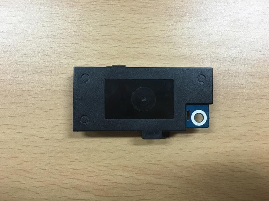
NLMSWLQ93T
Dec 22, 2015WiFi Module
Equipment Class
NII - Unlicensed National Information Infrastructure TX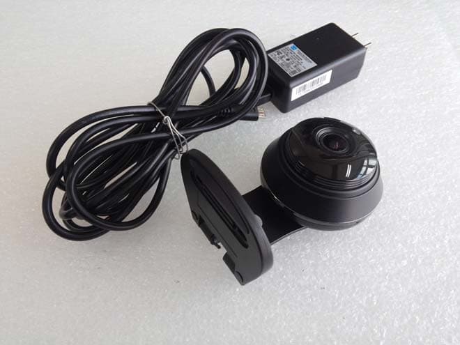
NLMSNHV6414BN
Nov 19, 2015SMART HOME CAMERA
Equipment Class
DTS - Digital Transmission System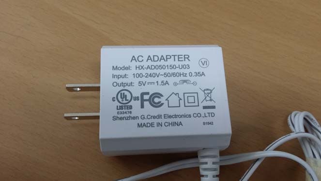
NLMSEP1003RWN
Nov 16, 2015Wireless Baby Camera
Equipment Class
DSS - Part 15 Spread Spectrum Transmitter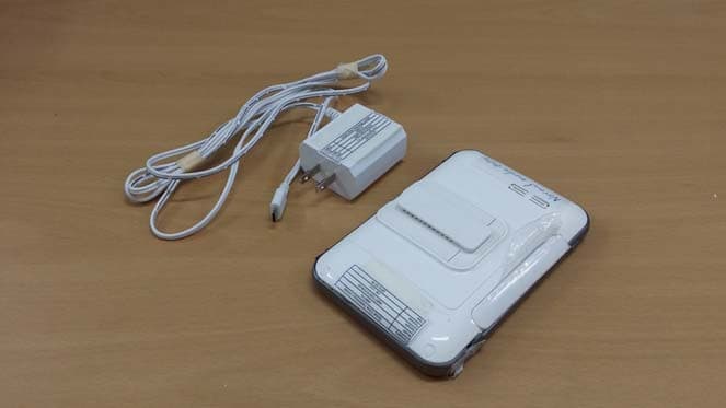
NLMSEW3043WN
Nov 16, 2015Wireless Baby Monitor
Equipment Class
DSS - Part 15 Spread Spectrum Transmitter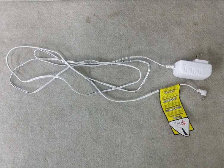
NLMSEW3036W
Jun 16, 2015Baby Monitor
Equipment Class
DSS - Part 15 Spread Spectrum Transmitter