NOO-S2983-011Spectrum 700 Path 1/700 Path 2 RFIC MIMO SRAU
ADC Telecommunications Inc.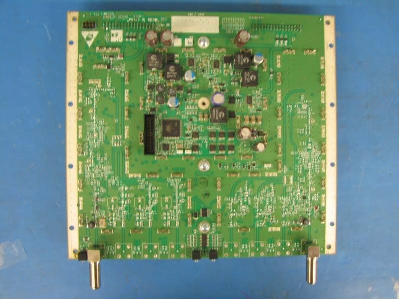
Click to zoom
Application Details
- Equipment Class
- AMP - Amplifier
- Date of Grant
- Sep 15, 2011
- Application Purpose
- Original Equipment
- Date of Application
- Sep 15, 2011
- Equipment Note
- Spectrum 700 Path 1/700 Path 2 RFIC MIMO SRAU
- Frequency Range
- 746.00000000 - 756.00000000
- Company
- ADC Telecommunications Inc.
- Country
- United States
Documents & Files
Document Text
Text extracted from the exhibit documents filed with the FCC. Open a document above to read the original.
Users Manual
InterReach Spectrum ™ Main and Secondary Remote Access Unit Installation Guide D-620731-0-20 Rev A Main Remote Access Unit Secondary Remote Access Unit ADCP-77-168 Issue 2 07/2011 ADC Telecommunications, Inc. P.O. Box 1101, Minneapolis, Minnesota 55440-1101 In U.S.A. and Canada: 1-800-366-3891 Outside U.S.A. and Canada: (952) 938-8080 Fax: (952) 917-1717 Copyright © 2011 ADC Telecommunications, Inc. All Rights Reserved. Information contained in this document is company private to ADC Telecommunications, Inc. and shall not be modified, used, copied, reproduced or disclosed in whole or in part without the written consent of ADC. Trademark Information ADC is a registered trademark and InterReach Spectrum is a trademark of ADC Telecommunications, Inc. No right, license, or interest to such trademarks is granted hereunder, and you agree that no such right, license, or interest shall be asserted by you with respect to such trademark. Other product names mentioned in this practice are for identification purposes only and may be trademarks or registered trademarks of their respective companies. Disclaimer of Liability Contents herein are current as of the date of publication. ADC reserves the right to change the contents without prior notice. Should the content of printed user documentation shipped with product differ from documentation provided on a product CD (inclusive of the associated Help modules), the printed user documentation supersedes the documentation on the product CD. In no event shall ADC be liable for any damages resulting from loss of data, loss of use, or loss of profits, and ADC further disclaims any and all liability for indirect, incidental, special, consequential or other similar damages. This disclaimer of liability applies to all products, publications and services during and after the warranty period. Specific Disclaimer for High-Risk Activities This Product is not specifically designed, manufactured, tested or intended for use in high-risk activities including, without restricting the generality of the foregoing, on-line control of aircraft, air traffic, aircraft navigation or aircraft communications; or in the design, construction, operation or maintenance of any nuclear facility. ADC (including its affiliates) and its suppliers specifically disclaim any express or implied warranty of fitness for such purposes or any other purposes. InterReach Spectrum Remote Access Unit Installation GuidePage 1 ADCP-77-168 • Issue 2 • 07/2011©2011 ADC Telecommunications, Inc. TABLE OF CONTENTS Preface.................................................................................................................... 1 InterReach Spectrum User Documentation .............................................................. 2 Document Cautions and Notes ............................................................................... 2 General Safety Precautions ................................................................................... 2 Standards Certification ......................................................................................... 3 Product Overview ..................................................................................................... 4 Main Remote Access Units..................................................................................... 5 MRAU Ports, Cable, and Connectors................................................................... 5 MRAU LEDs .................................................................................................... 6 Secondary Remote Access Units............................................................................. 7 SRAU Ports, Cable, and Connectors ................................................................... 7 SRAU LEDs .................................................................................................... 8 Install the RAUs and Antennas.................................................................................... 8 Mount the RAUs and Antennas............................................................................... 8 Connect the IFEU to the MRAU ............................................................................ 10 Connect the MRAU to SRAUs ............................................................................... 12 Configure the MRAUs and SRAUs ......................................................................... 13 Appendix A: Specifications ....................................................................................... 14 Spectrum System Specifications .......................................................................... 14 Remote Access Unit Specifications........................................................................ 15 Composite Power Out of RAU............................................................................... 15 Appendix B: 75-Ohm CATV Cable.............................................................................. 16 CATV Cable Requirements................................................................................... 16 Belden 1695A Coax Specifications ........................................................................ 17 Description .................................................................................................. 17 Overall Physical Characteristics....................................................................... 17 Overall Nominal Electrical Characteristics ......................................................... 18 Belden 7732A Coax Specifications ........................................................................ 19 Description .................................................................................................. 19 Overall Physical Characteristics....................................................................... 19 Overall Nominal Electrical Characteristics ......................................................... 19 Appendix C: Omni Antenna .…
Text truncated - open the document above for the full version.
Attestation Statements
Mailing Address: 1187 Park Place, Shakopee, Minnesota 55379 www.te.com September 1, 2011 Attn: Application Examiner, Reviewing Engineer Re: Attestation Statement I, the undersigned, attest that all testing done under my supervision was done in accordance with the Federal Communications Commission’s CFR 47 Part 27. The EUT fulfills the requirements of the Federal Communications Commission’s CFR 47 Part 27. Sincerely, Joshua J. Wittman Compliance Engineer Tele: 952 403-8322 Fax: 952 403-8858 Email: [email protected]
Cover Letter(s)
Mailing Address: 1187 Park Place, Shakopee, Minnesota 55379 www.te.com September 1, 2011 Attn: Application Examiner, Reviewing Engineer FCC ID: NOO-S2983-011 Re: Request of Confidentiality Pursuant to Sections 0.457(d)(1)(ii) and 0.459 of the Commission’s Rules, the Applicant hereby requests confidential treatment of information accompanying as outlined below: Schematics, Technical Description or Theory of Operation, Bill of Materials (BOM’s), and Block Diagrams The above materials contain trade secrets and proprietary information not customarily released to the public. The public disclosure of these matters might be harmful to the Applicant and provide unjustified benefits to its competitors. The Applicant understands that pursuant to Rule 0.457(d)(1)(ii), disclosure of this Application and all accompanying documentation will not be made before the date of the Grant for this Application. Sincerely, Joshua J. Wittman Compliance Engineer Tele: 952 403-8322 Fax: 952 403-8858 Email: [email protected]
Cover Letter(s)
Mailing Address: 1187 Park Place, Shakopee, Minnesota 55379 www.te.com September 1, 2011 Attn: Application Examiner, Reviewing Engineer Re: Name of EUT on Grant Spectrum 700 Path 1/700 Path 2 RFIC MIMO SRAU Sincerely, Joshua J. Wittman Compliance Engineer Tele: 952 403-8322 Fax: 952 403-8858 Email: [email protected]
External Photos
Spectrum 700 Path 1/AWS Path 1 SRAU Photos Front View 1 Rear View Front View Side View 1 Side View 2 Bottom View Internal Assembly 1 Internal Assembly 2 PCB IF Assembly Bottom View with shielding‐ SRAU PCB IF Assembly Bottom View without shielding‐ SRAU PCB IF Assembly Top View ‐ SRAU PCB Assembly Bottom View Ant Port with shielding – SRAU PCB Assembly Bottom View Ant Port without shielding – SRAU PCB Assembly Top View Ant Port with shielding ‐ SRAU PCB Assembly Top View Ant Port without shielding ‐ SRAU PCB Assembly Bottom View Ant Port with shielding – SRAU PCB Assembly Bottom View Ant Port without shielding – SRAU PCB Assembly Top View Ant Port with shielding ‐ SRAU PCB Assembly Top View Ant Port without shielding ‐ SRAU
ID Label/Location Info
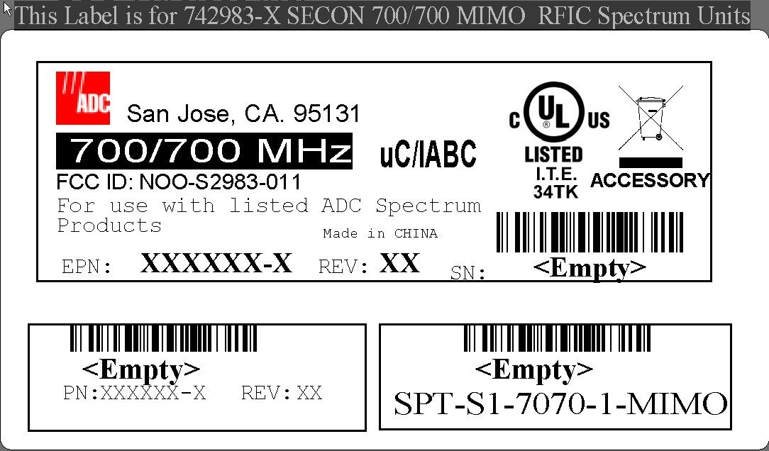
Spectrum 700 Path 1 /700 Path 2 RFIC MIMO SRAU FCC/IC Label Location
Internal Photos
Spectrum 700 Path 1/AWS Path 1 SRAU Photos Front View 1 Rear View Front View Side View 1 Side View 2 Bottom View Internal Assembly 1 Internal Assembly 2 PCB IF Assembly Bottom View with shielding‐ SRAU PCB IF Assembly Bottom View without shielding‐ SRAU PCB IF Assembly Top View ‐ SRAU PCB Assembly Bottom View Ant Port with shielding – SRAU PCB Assembly Bottom View Ant Port without shielding – SRAU PCB Assembly Top View Ant Port with shielding ‐ SRAU PCB Assembly Top View Ant Port without shielding ‐ SRAU PCB Assembly Bottom View Ant Port with shielding – SRAU PCB Assembly Bottom View Ant Port without shielding – SRAU PCB Assembly Top View Ant Port with shielding ‐ SRAU PCB Assembly Top View Ant Port without shielding ‐ SRAU
Parts List/Tune Up Info
Mailing Address: 1187 Park Place, Shakopee, Minnesota 55379 www.te.com June 7, 2011 Attn: Application Examiner, Reviewing Engineer Re: Tune-up Procedure At installation, the system automatically configures its gain to compensate for coaxial cable loss between the IFEU and the RAUs. When the system is brought on-line, the pilots are used as reference signals for system to set its gain to the correct levels When an RAU is connected to any IFEU port, it will automatically be recognized and commanded into service. If an RAU is disconnected, the IFEU indicates disconnect with LED Red/Blank pattern on the corresponding port. The system will maintain RAU disconnects, even through a power cycle, and a user command will be required to clear the disconnect status. The purpose for this is to maintain the last valid RAU configuration (usually on commissioning) so that if any unit is accidentally disconnected (or powered off), that disconnect is indicated even if the Hub is power cycled. The Pilot tone will be two tones (Low and High end of band) used to adjust the gain and slope to compensate for 75 Ohm cable between the IFEU and the RAU. The Pilot tone will have an attenuator to set the pilot level to a constant fixed level over temperature. A calibration tone per band will be generated in the URH and sent to the RAU via the IFEU. Sincerely, Joshua J. Wittman Compliance Engineer Tele: 952 403-8322 Fax: 952 403-8858 Email: [email protected]
RF Exposure Info
Mailing Address: 1187 Park Place, Shakopee, Minnesota 55379 www.te.com September 1, 2011 Attn: Application Examiner, Reviewing Engineer Since the Spectrum 700 Path 1/700 Path 2 RFIC MIMO SRAU is a low power device that is not hand-held, its antenna would rarely be within 20 cm of an individual, and the ERP is less than 3 watts, we are in compliance with SAR requirements of 2.1091. The maximum TX output power from the EUT antenna port is 17.99 dBm. The maximum gain antenna that could be for use with the EUT has a gain of 16.78 dBi. From the following equations: Peak Output of EUT at antenna Connector (dBm) + Gain of Antenna (dBd) = Peak TX Power (dBm) ERP 10*Log 10 (Peak TX Power * E 3 Watts) = Peak TX Power (dBm) ERP 17.99 dBm + 16.78 dBi = 34.77 dBm EIRP 34.77 dBm ERP = 3.0 Watts EIRP To convert to EIRP use the relation: EIRP = ERP X 1.64. (2.55 EIRP = 1.56 ERP) To convert to dBi to dBd use the relation: dBi = dBd + 2.14. (7.14 dBi = 5.0 dBd) Per OET 65: Maximum Permissible Exposure is 1.0 mW/cm 2 over 30 minutes. (1500 MHz - 100,000 MHz) The following equations determine the distance from the antenna that the power density is ≤ 1.0 mW/cm 2 . 3.0 Watts EIRP = 3.0*10 3 mWatts ERP 1.0 mW/cm 2 = 3.0*10 3 mW/(4*π*r 2 ) r= SQR(3.0*10 3 /4*π 1.0) r= 15.45 cm or 0.1545 Meters In addition, the following statement is in our installation manual: To comply with Maximum Permissible Exposure (MPE) requirements, antennas must be installed to provide at least 20 centimeters of separation from all persons per FCC 47CFR, Part 2.1091 and IC RSS-102, Section 2.5.2. Sincerely, Joshua J. Wittman Compliance Engineer Tele: 952 403-8322 Fax: 952 403-8858 Email: [email protected]
Test Report
TEST REPORT Report Number: 100488883MIN-001 Project Number: G100488883 Testing performed on the Spectrum 700 Path 1 / 700 Path 2 MIMO RFIC Secondary Remote Antenna Unit to 47 CFR, Part 27:2009, Enclosure Spurious Radiated Emissions For TE Connectivity / LGC Wireless Test Performed by: Test Authorized by: Intertek Testing Services NA, Inc. 7250 Hudson Blvd., Suite 100 Oakdale, MN 55128 USA TE Connectivity / LGC Wireless 541 E Trimble Road San Jose, CA 95131 USA Prepared by: Date: August 23, 2011 Richard Blonigen Reviewed by: Date: August 23, 2011 Norman Shpilsher This report is for the exclusive use of Intertek's Client and is provided pursuant to the agreement between Intertek and its Client. Intertek's responsibility and liability are limited to the terms and conditions of the agreement. Intertek assumes no liability to any party, other than to the Client in accordance with the agreement, for any loss, expense or damage occasioned by the use of this report. Only the Client is authorized to copy or distribute this report and then only in its entirety. Any use of the Intertek name or one of its marks for the sale or advertisement of the tested material, product or service must first be approved in writing by Intertek. The observations and test results in this report are relevant only to the sample tested. This report by itself does not imply that the material, product, or service is or has ever been under an Intertek certification program. This report must not be used to claim product endorsement by A2LA, NIST nor any other agency of the U.S. Government. EMC Report No: 100488883MIN-001 Page 2 of 16 TABLE OF CONTENTS 1.0 DESCRIPTION OF THE SAMPLE (EUT)................................ ................................................................ ............................................................ ........................................................ ............................ 3 33 3 2.0 TEST SUMMARY................................ ................................................................ ................................................................ ................................................................ .......................................................... .................................................... .......................... 4 44 4 2.1 Statement of the Measurement Uncertainty............................................................4 3.0 EQUIPMENT UNDER TEST................................ ................................................................ ................................................................ ................................................................ ............................................ ........................ ............ 5 55 5 3.1 Power Configuration..........................................................................................5 3.2 EUT Configuration............................................................................................5 3.3 Environmental conditions....................................................................................6 4.0 TEST CONDITIONS AND RESULTS................................ ................................................................ ................................................................ ................................................................ ................................. .. . 7 77 7 4.1 Enclosure Spurious Radiated Emissions...............................................................7 5.0 TEST EQUIPMENT................................ ................................................................ ................................................................ ................................................................ ....................................................... .............................................. .......................16 1616 16 EMC Report No: 100488883MIN-001 Page 3 of 16 1.0 DESCRIPTION OF THE SAMPLE (EUT) Model: Spectrum 700 Path 1 / 700 Path 2 MIMO RFIC Secondary Remote Antenna Unit SPT-S1-7070-1-MIMO Type of EUT: Repeater / Booster Operating Frequency Range: 728 – 756MHz Company: TE Connectivity / LGC Wireless Customer: Sue Cyr Address: 541 E. Trimble Road San Jose, CA 95131 USA Phone: 408-952-2445 Fax: 408-952-2645 e-mail: [email protected] Test Standards: EN 55022:2006 +A1:2007, Class EN 55011:2007 +A2:2007, Group , Class 47 CFR, Part 27:2009, Enclosure Spurious Radiated Emissions ICES-003, Issue 4:2004 EN 55014-1:2006 EN 61326-1:2006 Class for Radiated and Conducted Emissions Basic Immunity Test Requirements Immunity Test Requirements for Industrial Locations EN 60601-1-2:2001 +A1:2006 EN 61000-6-3:2007 EN 61000-6-4:2007 EN 61000-3-2:2006 EN 61000-3-3:1995 +A1:2001 +A2:2006 EN 61000-6-1:2007 EN 61000-6-2:2005 EN 55024:1998 + A1:2001 + A2:2003 Date Sample Submitted: August 17, 2011 Test Work Started: August 17, 2011 Test Work Completed: August 17, 2011 Test Sample Conditions: Damaged Poor (Usable) Good Prototype Production Used EMC Report No: 100488883MIN-001 Page 4 of 16 2.0 TEST SUMMARY Referring to the performance criteria and the operating mode during the tests specified in this report, the equipment complies with the requirements according to the following standards. TEST STANDARD TEST RESULT Part 27 Enclosure Spurious Radiated Emissions Pass 2.1 Statement of the Measurement Uncertainty Note: The measured result in this report is within the specification limits by more than the measurement uncertainty; the measured result indicates that the product tested complies with the specification limit. The expanded uncertainty (k = 2) for radiated emissions from 30 to 1000 MHz has been determined to be: ±4 dB at 10m and ±5.4 dB at 3m The expanded uncertainty (k = 2) for conducted emissions from 150 kHz to 30 MHz has been determined to be: ±2.6 dB EMC Report No: 100488883MIN-001 Page 5 of 16 3.0 EQUIPMENT UNDER TEST 3.1 Power Configuration Rated voltage: 120VAC 230VAC 400VAC VDC Othe…
Text truncated - open the document above for the full version.
Test Report
MN110622_700P1_700P2_RFIC_MIMO_SRAU Page 1 Test Report Summary FCC CFR 47, Part 27 Wireless Communications Service Manufacturer: ADC Telecommunications Name of Equipment: Spectrum 700Path 1/700Path 2 RFIC MIMO SRAU Model Number(s): SPT-S1-7070-1-MIMO Manufacturer’s Address: 1187 Park Place Shakopee, MN 55739 Test Report Number: MN110902_700P1_700P2 RFIC MIMO SRAU Test Date(s): 17 August, 2011 (Intertek) 25 May, 2011 (ADC) 20 June, 2011 (ADC) 26, 29, & 30 August, 2011 (ADC) According to testing performed at Intertek, the above-mentioned unit is in accordance with the applicable electromagnetic compatibility (EMC) portions of the requirements defined in FCC Part 27. It is the manufacturer’s responsibility to assure that additional production units of this model are manufactured with identical electrical and mechanical characteristics. Any modifications necessary for compliance made during testing on the above mentioned date(s) must be implemented in all production units for compliance to be maintained. All testing was done in accordance with the Federal Communications Commission’s CFR 47 Part 27. The EUT fulfills the requirements of the Federal Communications Commission’s CFR 47 Part 27. Date: 2 September, 2011 Location: Intertek Testing Services (INTERTEK) ADC Telecommunications 7250 Hudson Blvd., Suite 100 1187 Park Place Oakdale, MN 55128 Shakopee, MN 55379 Phone: (651) 730-1188 Phone: (952) 403-8340 Fax: (651) 730-1282 Fax: (952) 403-8858 Testing Conducted by (ADC): And Report Written by: Joshua J. Wittman Compliance Engineer MN110622_700P1_700P2_RFIC_MIMO_SRAU Page 2 EMC Emission – T E S T R E P O R T Test Report File Number: MN110902_700P1_700P2 RFIC MIMO SRAU Date of Issue: 2 September, 2011 Model Number(s): SPT-S1-7070-1-MIMO Product Name: Spectrum 700Path 1/700Path 2 RFIC MIMO SRAU Product Type: Repeater/Booster Applicant: ADC Telecommunications Manufacturer: ADC Telecommunications License Holder: ADC Telecommunications Address: P.O. Box 1101 Minneapolis, MN 55440-1101 Test Result: ▪ Positive ▫ Negative Test Project Number: 100488883MIN-001 Reference(s) Total pages including Appendices: 151 MN110622_700P1_700P2_RFIC_MIMO_SRAU Page 3 1.0 TABLE OF CONTENTS 1.0 Table of Contents ................................................................................................. 3 2.0 Revision Description .............................................................................................. 4 3.0 Documentation ..................................................................................................... 4 3.1 Test Regulations ................................................................................................ 4 3.2 Test Operation Mode .......................................................................................... 5 3.3 Configuration of the Device Under Test: ................................................................ 5 3.4 Product Options: ................................................................................................ 5 3.5 EUT Specifications and Requirements: .................................................................. 5 3.6 Cables: ............................................................................................................. 5 3.7 Power Requirements: ......................................................................................... 5 3.8 Typical Installation and/or Operating Environment: ................................................. 5 3.9 Other Special Requirements: ............................................................................... 5 3.10 EUT Software: ................................................................................................ 5 3.11 EUT System Components ................................................................................. 6 3.12 Support Equipment .......................................................................................... 6 3.13 Deviations from Standard: ................................................................................ 6 3.14 General Remarks: ........................................................................................... 6 3.15 Summary: ...................................................................................................... 6 4.0 Test Set-Up Drawings and Photos ........................................................................... 7 4.1 Test Set-up Photo, Radiated Emissions .................................................................. 7 4.2 Test Set-up Drawings ......................................................................................... 9 5.0 Test Results ....................................................................................................... 11 5.1.1 27.50 RF Power Limits ................................................................................. 11 5.1.2 27.54 Frequency Stability ............................................................................ 12 5.1.3 27.53 Emission Limitations .......................................................................... 13 6.0 Test Equipment .................................................................................................. 14 7.0 Appendix A ........................................................................................................ 15 7.1 Conducted Emission Limits Test ......................................................................... 16 7.2 Conducted Output Power Test ............................................................................ 69 7.3 Frequency Stability Test .................................................................................... 72 7.4 Intermodulation Test ........................................................................................ 74 7.5 Occupied Bandwidth Modulation Test ................................................................. 129 8.0 Appendix B .........................................................................…
Text truncated - open the document above for the full version.
Contact Information
Applicant
Joshua Wittman(Compliance Engineer)
Test Firm
Intertek Testing Services NA, Inc.Andrew Waytulonis
Technical Specifications
| # | Rule Parts | Frequency Range | Power Output | Emission | Tolerance |
|---|---|---|---|---|---|
| 2 | 27 | 746 MHz - 756 MHz | 52.00 mW | D7D | Amp |
Other Applications from ADC Telecommunications Inc.

NOO-F0851-111
Mar 31, 2015FSN-2525-1-TDD
Equipment Class
B2I - Part 20 Industrial Booster (CMRS)
NOO-S2782-011
Mar 19, 2015SPT-S3-2323-12-HP
Equipment Class
B2I - Part 20 Industrial Booster (CMRS)
NOO-S2195-011
May 14, 2014InterReach Spectrum Remote Access Unit
Equipment Class
B2I - Part 20 Industrial Booster (CMRS)
NOO-F0688-011
Feb 05, 2013InterReach Fusion 700 MHz (Upper C) LTE, 850 MHz and high power 1900 MHz Multi-Band
Equipment Class
PCB - PCS Licensed Transmitter
NOO-F0699-011
Jan 23, 2013InterReach Fusion� 700 MHz (Lower ABC), AWSMIMO HP
Equipment Class
TNB - Licensed Non-Broadcast Station Transmitter