NOODAS9M-4E-WLGCell EGSM
ADC Telecommunications Inc.
Click to zoom
Application Details
- Equipment Class
- AMP - Amplifier
- Date of Grant
- Aug 23, 2001
- Application Purpose
- Original Equipment
- Date of Application
- Aug 23, 2001
- Equipment Note
- LGCell EGSM
- Frequency Range
- 880.00000000 - 915.00000000
- Company
- ADC Telecommunications Inc.
- Country
- United States
Documents & Files
Document Text
Text extracted from the exhibit documents filed with the FCC. Open a document above to read the original.
Users Manual
PN 8700-10 620003-0 Installation, Operation, and Reference Manual InterReach Unison TM PN 8700-10 620003-0 Installation, Operation, and Reference Manual InterReach Unison TM InterReach Unison User Guide and Reference ManualPN 8700-10 620003-0 This manual is produced for use by LGC Wireless personnel, licensees, and customers. The information contained herein is the property of LGC Wireless. No part of this document may be reproduced or transmitted in any form or by any means, electronic or mechanical, for any purpose, without the express written permission of LGC Wireless. LGC Wireless reserves the right to make changes, without notice, to the specifications and materials contained herein, and shall not be responsible for any damages caused by reliance on the material as presented, including, but not limited to, typographical and listing errors. Your comments are welcome – they help us improve our products and documentation. Please address your comments to LGC Wireless, Inc. corporate headquarters in San Jose, California: Address2540 Junction Avenue San Jose, California 95134-1902 USA Attn: Marketing Dept. Phone1-408-952-2400 Fax1-408-952-2410 Help Hot Line 1-800-530-9960 (U.S. only) +1-408-952-2400 (International) +44(0) 1223 597812 (Europe) Web Addresshttp://www.lgcwireless.com [email protected] [email protected] Copyright © 2001 by LGC Wireless, Inc. Printed in USA. All rights reserved. Trademarks All trademarks identified by ™ or ® are trademarks or registered trademark of LGC Wireless, Inc. All other trademarks belong to their respective owners. PN 8700-10InterReach Unison User Guide and Reference Manual 620003-0 Limited Warranty Seller warrants articles of its manufacture against defective materials or workmanship for a period of one year from the date of shipment to Purchaser, except as provided in any warranty applicable to Purchaser on or in the package containing the Goods (which warranty takes precedence over the following warranty). The liability of Seller under the foregoing warranty is limited, at Seller’s option, solely to repair or replacement with equivalent Goods, or an appropriate adjustment not to exceed the sales price to Purchaser, provided that (a) Seller is notified in writing by Purchaser, within the one year warranty period, promptly upon discovery of defects, with a detailed description of such defects, (b) Purchaser has obtained a Return Materials Authorization (RMA) from Seller, which RMA Seller agrees to provide Purchaser promptly upon request, (c) the defective Goods are returned to Seller, transportation and other applicable charges prepaid by the Purchaser, and (d) Seller’s examination of such Goods discloses to its reasonable satisfaction that defects were not caused by negligence, misuse, improper installation, improper maintenance, accident or unauthorized repair or alteration or any other cause outside the scope of Purchaser’s warranty made hereunder. Notwithstanding the foregoing, Seller shall have the option to repair any defective Goods at Purchaser’s facility. The original warranty period for any Goods that have been repaired or replaced by seller will not thereby be extended. In addition, all sales will be subject to standard terms and conditions on the sales contract. InterReach Unison User Guide and Reference ManualPN 8700-10 620003-0 PN8700-10InterReach Unison User Guide and Reference Manuali 620003-0 PRELIMINARY Table of Contents SECTION 1General Information . . . . . . . . . . . . . . . . . . . . . . 1-1 1.1 Purpose and Scope . . . . . . . . . . . . . . . . . . . . . . . . . . . . . . . . . 1-2 1.2 Conventions in this Manual . . . . . . . . . . . . . . . . . . . . . . . . . . 1-3 1.3 Acronyms in this Manual . . . . . . . . . . . . . . . . . . . . . . . . . . . . 1-4 1.4 Standards Conformance . . . . . . . . . . . . . . . . . . . . . . . . . . . . . 1-6 1.5 Related Publications. . . . . . . . . . . . . . . . . . . . . . . . . . . . . . . . 1-6 SECTION 2 InterReach™ Unison System Description . . . . 2-1 2.1 System Overview . . . . . . . . . . . . . . . . . . . . . . . . . . . . . . . . . . 2-1 2.2 System Hardware . . . . . . . . . . . . . . . . . . . . . . . . . . . . . . . . . . 2-3 2.3 System Software. . . . . . . . . . . . . . . . . . . . . . . . . . . . . . . . . . . 2-4 2.4 System OA&M Capabilities. . . . . . . . . . . . . . . . . . . . . . . . . . 2-5 2.4.1 Configuring, Maintaining, and Monitoring Unison Locally. . 2-6 2.4.2 Monitoring and Maintaining Unison Remotely . . . . . . . . . . . 2-7 2.4.3 Using Alarm Contact Closures . . . . . . . . . . . . . . . . . . . . . . . . 2-8 2.5 System Connectivity. . . . . . . . . . . . . . . . . . . . . . . . . . . . . . . . 2-9 2.6 System Operation . . . . . . . . . . . . . . . . . . . . . . . . . . . . . . . . . 2-10 2.7 System Specifications. . . . . . . . . . . . . . . . . . . . . . . . . . . . . . 2-11 2.7.1 Physical Specifications . . . . . . . . . . . . . . . . . . . . . . . . . . . . . 2-11 2.7.2 Environmental Specifications . . . . . . . . . . . . . . . . . . . . . . . . 2-12 2.7.3 Operating Frequencies. . . . . . . . . . . . . . . . . . . . . . . . . . . . . . 2-12 2.7.4 RF End-to-End Performance. . . . . . . . . . . . . . . . . . . . . . . . . 2-13 SECTION 3Unison Main Hub . . . . . . . . . . . . . . . . . . . . . . . . 3-1 3.1 Main Hub Front Panel . . . . . . . . . . . . . . . . . . . . . . . . . . . . . . 3-3 3.1.1 Optical Fiber Uplink/Downlink Ports. . . . . . . . . . . . . . . . . . . 3-4 3.1.2 Communications RS-232 Serial Connector . . . . . . . . . . . . . . 3-4 3.1.3 LED Indicators . . . . . . . . . . . . . . . . . . . . . . . . . . . . . . . . . . . . 3-6 3.2 Main Hub Rear Panel . . . . . . . . . . . . . . . . . . . . . . . . . . . . . . . 3-8 3.2.1 Main Hub Rear Panel Connectors. . . . . . . . . . . . . . . . . . . . . . 3-9 3.2.1.1 N-type Female Connectors . . . . . . . . . . . . . . . . . . . . . . 3-9 PRELIMINARY iiInterReach Unison User Guide and Reference Manu…
Text truncated - open the document above for the full version.
Attestation Statements
ATTESTATION STATEMENT FCC ID: NOO-DAS9M-4E-W LGCell EGSM Summary: All relevant tests according to FCC CFR Part 90 were performed. The equipment detailed above fulfills the general approval requirements identified above. For, and on behalf of, BABT Srini Chandrasekaran Lead EMC Engineer
External Photos
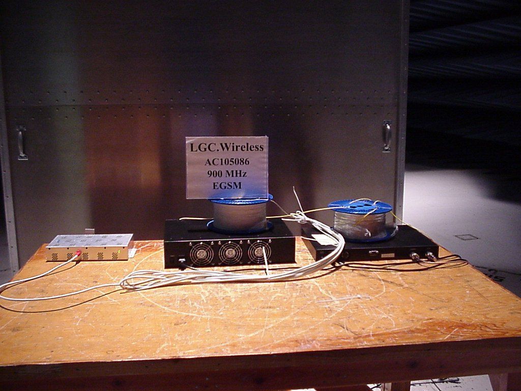
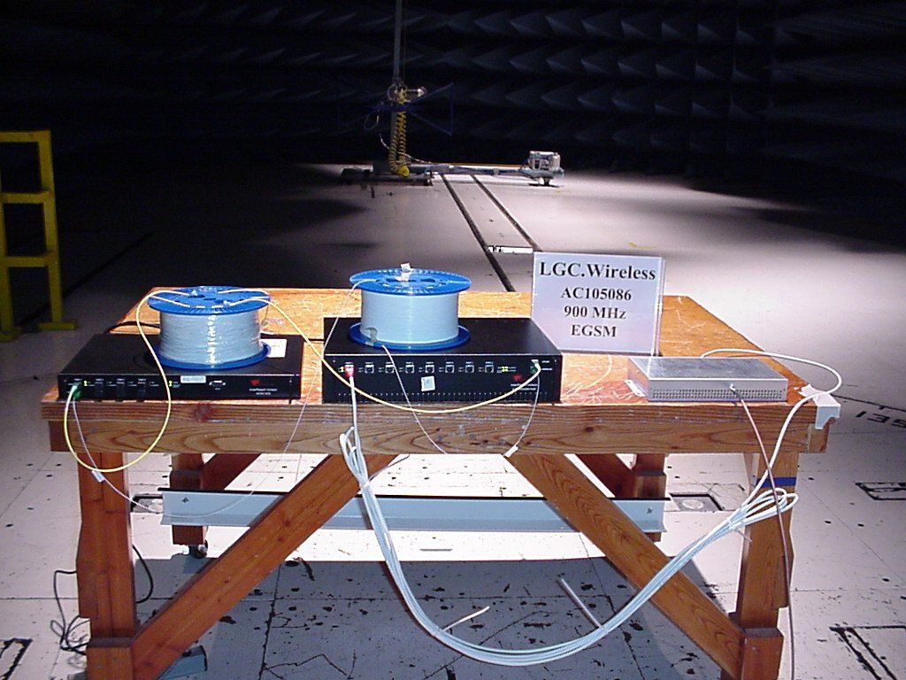
Back of expansion hub Back of main hub Back of RAU Front of RAU Front of expansion hub Front of main hub
ID Label/Location Info
Expansion Hub Labels Main Hub Labels
Internal Photos
Inside expansion hub Inside of main hub (without shields) Inside of main hub (with shields) Inside RAU (without shields) Inside RAU (with shields)
Test Report
Report No. AC105086FP90-LGCell900MHz (FCC ID:DAS9M-4E-W) - MEASUREMENT AND TECHNICAL REPORT LGC Wireless, Inc. 2540 Junction Avenue San Jose, CA 95134 DATE: 22 August 2001 This Report Concerns: Original Grant: X Class II Change: EEquipment Type: LGCell EGSM Deferred grant requested per 47 CFR 0.457(d)(1)(ii)? Yes: Defer until: No: X LCG Wireless Inc., agrees to notify the Commission by: Of the intended date of announcement of the product so that the grant can be issued on that date. Transition Rules Request per 15.37? Yes: *No: ( * ) FCC Part 2, Paragraphs, 2.1046, 2.1051, 2.1053, 2.1055 and Part 90.. Report Prepared By: TÜV Product Service 4855 Patrick Henry Drive Bldg. 6 Santa Clara, CA 95054 Report No. AC105086FP90-LGCell900MHz (FCC ID: DAS9M-4E-W) Page 1 of 36 D I R E C T O R Y Page No. 1 GENERAL INFORMATION 2 1.1 Product Description 3 1.2 Related Submittal Grant 3 1.3 Tested System Details 3 1.4 Statement of Measurement Uncertainty 3 1.5 Test Facility 3 1.6 Part 2 Requirements 4 2 SYSTEM TEST CONFIGURATION 4 2.1 Justification 4 2.2 EUT Software Exercise 4 2.3 Special Accessories 4 2.4 Equipment Modifications 4 2.5 Configuration of Tested System 4 2.1046 RF Power Output 5 2.1047 Modulation Characteristics 6 2.1049 Occupied Bandwidth 6 2.1051 Spurious Emissions At The Antenna Terminals 11 2.1053 Field Strength of Spurious Radiations 12 2.1055 Frequency Stability 13 3 RADIATED EMISSION EQUIPMENT DATA Field Strength Calculation 18 4 CONDUCTED EMISSION EQUIPMENT DATA 19 5 Signature Page 36 Report No. AC105086FP90-LGCell900MHz (FCC ID: DAS9M-4E-W) Page 2 of 36 1.GENERAL INFORMATION 1.1 Product Description EUT Description: The system is a distributed in-building antenna system that enables wireless uninterrupted communication. The Main Hub of the system receives an RF signal from either a roof top antenna or a base station. The Main Hub down converts this signal to an IF signal and passes the signal to the Expansion Hub via fiber. The Expansion Hub does some additional filtering and passes the signal via Cat5 cable on to the Remote Antenna Unit, the RAU. The RAU up converts the signal back to an RF signal and rebroadcasts it. The system extends the wireless coverage area by bringing wireless signals into hard to penetrate structures. EUT Name: LGCell EGSM Model No. DAS9M-4E-W Product Options: N/A Serial No. Not Serialized Configurations To Be Tested: LGCell EGSM compromising of Main Hub, Expansion, and Remote Antenna Unit. Power Requirements Voltage: 120 VAC (If battery powered, make sure battery life is sufficient to complete testing.) No. Of Phases: N/A Current: Amps / Phase (Max): 5 A Current: Amps / Phase (Nominal): N/A Typical Installation and / or Operating Environment TELECOM EUT Power Cable n - Permanent or o - Removable o - Shielded or n - Unshielded Length (In Meters): 1.5 n Not Applicable EUT I/O Ports and Cables: CONNECTION: Signal Generator To Main Hub and RAU to Spectrum Analyzer: RF Cable. SHIELD: Yes CONNECTORS: Yes TERMINATION TYPE: SMA or N LENGTH: REMOVABLE: Yes CONNECTION: Expansion Hub to RAU: Cat5 Cable SHIELD: No CONNECTORS: Yes TERMINATION TYPE: RJ 45 LENGTH: 50 m max REMOVABLE: Yes CONNECTION: Main Hub to expansion Hub: Fiber SHIELD: No Report No. AC105086FP90-LGCell900MHz (FCC ID: DAS9M-4E-W) Page 3 of 36 1. GENERAL INFORMATION (continued) 1.2 Related Submittal / Grant None 1.3 TESTED SYSTEM DETAILS The FCC IDs for all equipment, plus descriptions of all cables used in test system are: None. 1.4 STATEMENT OF MEASUREMENT UNCERTAINTY The data and results referenced in this document are accurate. The reader is cautioned that there is some measurement variability due to the tolerances of the test equipment that can contribute to a nominal product measurement uncertainty. Furthermore, component differences and manufacturing process variability of production units similar to that tested may result in additional product uncertainty. If necessary, refer to the test lab for the actual measurement uncertainty for specific tests. 1.5 TEST FACILITY All measurements and tests were performed by: TÜV Product Service 4855 Patrick Henry Drive Building 6 Santa Clara, CA 95054 The Test Site Data and performance comply with ANSI 63.4 and are registered with the FCC, 7435 Oakland Mills Rd., Columbia Maryland 21046. All Measurement Data is acquired according to the content of FCC Measurement Procedure and ANSI C63.4, unless supplemented with additional requirements as noted in the test report. Report No. AC105086FP90-LGCell900MHz (FCC ID: DAS9M-4E-W) Page 4 of 36 1.6 Part 2 Requirements Equipment Specifications Frequency Range In MHz Rated RF Power In Watts Frequency Tolerance %, Hz, ppm Emission Designator (see CFR §2.201 and § 2.202) Microprocessor Model Number 880- 915 925- 960 0.01 +/- 5ppm F8W , DXW, F1D, F9W 2. SYSTEM TEST CONFIGURATION 2.1 Justification The LGCell EGSM was tested in the configuration shown in the block diagram. 2.2 EUT Exercise Software None 2.3 Special Accessories None. 2.4 Modifications None. 2.5 Configuration of tested System See Block Diagram. Report No. AC105086FP90-LGCell900MHz (FCC ID: DAS9M-4E-W) Page 5 of 36 RF Power Output – 2.1046 Uplink Channel Frequency (MHz) Peak Power Level (dBm) Low 880.000 -12.2 Mid 897.500 -14.7 High 915.000 -15.9 Downlink Channel Frequency (MHz) Peak Power Level (dBm) Low 925.000 .8 Mid 942.500 5.1 High 960.000 4.0 Test Equipment used: Model No. Description Manufacturer Serial No. Due Calib. Date n - 8566B Spectrum Analyzer Hewlett Packard 2816A18342 9/25/01 n - 8656B Signal Generator Hewlett Packard 2523A03399 4/9/02 n - HP8491B Attenuator Hewlett Packard 35958 N/A Report No. AC105086FP90-LGCell900MHz (FCC ID: DAS9M-4E-W) Page 6 of 36 Occupied Bandwidth (2.1049) Minimum Requirement: Section 2.1049(i); transmitters designed for other types of modulation –when modulated by an appropriate signal of sufficient amplitude to be represented of the type of service in which used. A description of the input signal should be supplied. T…
Text truncated - open the document above for the full version.
Contact Information
Applicant
Joshua Wittman(Compliance Engineer)
Test Firm
MET LaboratoriesAlvin Ilarina
Technical Specifications
| # | Rule Parts | Frequency Range | Power Output | Emission | Tolerance |
|---|---|---|---|---|---|
| 8 | 9 | 880 MHz - 915 MHz | 10.00 mW | F1D | 5 ppm |
Other Applications from ADC Telecommunications Inc.

NOO-F0851-111
Mar 31, 2015FSN-2525-1-TDD
Equipment Class
B2I - Part 20 Industrial Booster (CMRS)
NOO-S2782-011
Mar 19, 2015SPT-S3-2323-12-HP
Equipment Class
B2I - Part 20 Industrial Booster (CMRS)
NOO-S2195-011
May 14, 2014InterReach Spectrum Remote Access Unit
Equipment Class
B2I - Part 20 Industrial Booster (CMRS)
NOO-F0688-011
Feb 05, 2013InterReach Fusion 700 MHz (Upper C) LTE, 850 MHz and high power 1900 MHz Multi-Band
Equipment Class
PCB - PCS Licensed Transmitter
NOO-F0699-011
Jan 23, 2013InterReach Fusion� 700 MHz (Lower ABC), AWSMIMO HP
Equipment Class
TNB - Licensed Non-Broadcast Station Transmitter