NOOFSN-809019-2InterReach Fusion FSN-809019-2
ADC Telecommunications Inc.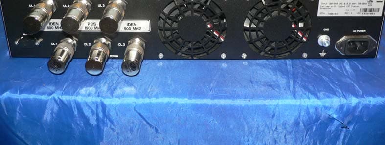
Click to zoom
Application Details
- Equipment Class
- PCB - PCS Licensed Transmitter
- Date of Grant
- Nov 14, 2007
- Application Purpose
- Original Equipment
- Date of Application
- Nov 14, 2007
- Equipment Note
- InterReach Fusion FSN-809019-2
- Frequency Range
- 1930.00000000 - 1995.00000000
- Company
- ADC Telecommunications Inc.
- Country
- United States
Documents & Files
Document Text
Text extracted from the exhibit documents filed with the FCC. Open a document above to read the original.
Users Manual
D-620610-0-20 Rev A Installation, Operation, and Reference Manual InterReach Fusion TM ® D-620610-0-20Help Hot Line (U.S. only): 1-800-530-9960 Rev ACONFIDENTIAL D-620610-0-20Help Hot Line (U.S. only): 1-800-530-9960 Rev ACONFIDENTIAL This manual is produced for use by LGC Wireless personnel, licensees, and customers. The information contained herein is the property of LGC Wireless. No part of this document may be reproduced or transmitted in any form or by any means, electronic or mechanical, for any purpose, without the express written permission of LGC Wireless. LGC Wireless reserves the right to make changes, without notice, to the specifications and materials contained herein, and shall not be responsible for any damages caused by reliance on the material as presented, including, but not limited to, typographical and listing errors. Your comments are welcome – they help us improve our products and documentation. Please address your comments to LGC Wireless, Inc. corporate headquarters in San Jose, California: Address2540 Junction Avenue San Jose, California 9513441902 USA Attn: Marketing Dept. Phone14408495242400 Fax14408495242410 Help Hot Line 14800453049960 (U.S. only) +14408495242400 (International) Web Address http://www.lgcwireless.com [email protected] [email protected] Copyright © 2006 by LGC Wireless, Inc. Printed in USA. All rights reserved. Trademarks All trademarks identified by ™ or ® are trademarks or registered trademarks of LGC Wireless, Inc. All other trademarks belong to their respective owners. InterReach Fusion Installation, Operation, and Reference Manual CONFIDENTIALD-620610-0-20 Rev D Limited Warranty Seller warrants articles of its manufacture against defective materials or workmanship for a period of one year from the date of shipment to Purchaser, except as provided in any warranty applicable to Purchaser on or in the package containing the Goods (which warranty takes precedence over the following warranty). The liability of Seller under the foregoing warranty is limited, at Seller’s option, solely to repair or replacement with equivalent Goods, or an appropriate adjustment not to exceed the sales price to Purchaser, provided that (a) Seller is notified in writing by Purchaser, within the one year warranty period, promptly upon discovery of defects, with a detailed description of such defects, (b) Purchaser has obtained a Return Materials Authorization (RMA) from Seller, which RMA Seller agrees to provide Purchaser promptly upon request, (c) the defective Goods are returned to Seller, transportation and other applicable charges prepaid by the Purchaser, and (d) Seller’s examination of such Goods discloses to its reasonable satisfaction that defects were not caused by negligence, misuse, improper installation, improper maintenance, accident or unauthorized repair or alteration or any other cause outside the scope of Purchaser’s warranty made hereunder. Notwithstanding the foregoing, Seller shall have the option to repair any defective Goods at Purchaser’s facility. The original warranty period for any Goods that have been repaired or replaced by seller will not thereby be extended. In addition, all sales will be subject to standard terms and conditions on the sales contract. Licensed Operators LGC Wireless’ equipment is designed to operate in the licensed frequency bands of mobile, cellular, and PCS operators. In the USA, the EU, and most countries this equipment may only be used by the licensee, his authorized agents or those with written authorization to do so. Similarly, unauthorized use is illegal, and subjects the owner to the corresponding legal sanctions of the national jurisdiction involved. Ownership of LGC Wireless equipment carries no automatic right of use. InterReach Fusion Installation, Operation, and Reference Manual1 D-620610-0-20 Rev ACONFIDENTIAL Table of Contents SECTION 1General Information . . . . . . . . . . . . . . . . . . . . . . 1-1 1.1 Firmware Release . . . . . . . . . . . . . . . . . . . . . . . . . . . . . . . . . . 141 1.2 Purpose and Scope . . . . . . . . . . . . . . . . . . . . . . . . . . . . . . . . . 141 1.3 Conventions in this Manual . . . . . . . . . . . . . . . . . . . . . . . . . . 142 1.4 Standards Conformance . . . . . . . . . . . . . . . . . . . . . . . . . . . . . 143 1.5 Related Publications . . . . . . . . . . . . . . . . . . . . . . . . . . . . . . . . 143 SECTION 2 InterReach Fusion System Description . . . . . . . . . . . . . . . . . . . . . . 2-1 2.1 System Overview . . . . . . . . . . . . . . . . . . . . . . . . . . . . . . . . . . 241 2.2 System Hardware Description . . . . . . . . . . . . . . . . . . . . . . . . 243 2.3 System OA&M Capabilities Overview . . . . . . . . . . . . . . . . . 244 2.3.1 System Monitoring and Reporting . . . . . . . . . . . . . . . . . . . . . 245 2.3.2 Using Alarm Contacts . . . . . . . . . . . . . . . . . . . . . . . . . . . . . . . 246 2.4 System Connectivity . . . . . . . . . . . . . . . . . . . . . . . . . . . . . . . . 247 2.5 System Operation . . . . . . . . . . . . . . . . . . . . . . . . . . . . . . . . . . 248 2.6 System Specifications . . . . . . . . . . . . . . . . . . . . . . . . . . . . . . . 249 2.6.1 RF End4to4End Performance . . . . . . . . . . . . . . . . . . . . . . . . . 2411 SECTION 3Fusion Main Hub . . . . . . . . . . . . . . . . . . . . . . . . . 3-1 3.1 Fusion Main Hub Overview . . . . . . . . . . . . . . . . . . . . . . . . . . 341 3.2 Fusion Main Hub Front Panel . . . . . . . . . . . . . . . . . . . . . . . . . 344 3.2.1 Optical Fiber Uplink/Downlink Ports . . . . . . . . . . . . . . . . . . . 345 3.2.2 Communications RS4232 Serial Connector . . . . . . . . . . . . . . 345 3.2.3 Main Hub LED Indicators . . . . . . . . . . . . . . . . . . . . . . . . . . . . 345 3.3 Fusion Main Hub Rear Panel . . . . . . . . . . . . . . . . . . . . . . . . . 348 3.3.1 Fusion Main Hub Rear Panel Connectors . . . . . . . . . . . . . . . . 348 3.3.1.1 94pin D4sub…
Text truncated - open the document above for the full version.
Users Manual
InterReach Fusion Installation, Operation, and Reference Manual741 D-620610-0-20 Rev ACONFIDENTIAL SECTION 7Installing Fusion This section contains the following subsections: • Section 7.1 Installation Requirements . . . . . . . . . . . . . . . . . . . . . . . . . . . . . . . 741 • Section 7.2 Safety Precautions . . . . . . . . . . . . . . . . . . . . . . . . . . . . . . . . . . . . 743 • Section 7.3 Preparing for System Installation . . . . . . . . . . . . . . . . . . . . . . . . . 746 • Section 7.4 Fusion Installation Procedures . . . . . . . . . . . . . . . . . . . . . . . . . . 7410 • Section 7.5 Splicing Fiber Optic Cable . . . . . . . . . . . . . . . . . . . . . . . . . . . . . 7437 • Section 7.6 Interfacing the Fusion Main Hub to an RF Source . . . . . . . . . . 7439 • Section 7.7 Connecting Contact Alarms to a Fusion System . . . . . . . . . . . . 7449 • Section 7.8 Alarm Monitoring Connectivity Options . . . . . . . . . . . . . . . . . . 7457 7.1 Installation Requirements Before and during installation, keep in mind these sources of potential problems: • Faulty cabling/connector • Dirty connectors and ports • Malfunction of one or more Fusion components • Antenna, base station, or repeater problem • External RF interface • Tripped circuit breaker • Equipment is not grounded • Using a crossover Ethernet cable that does not support full hardware handshaking when using AdminBrowser Installation Requirements 742InterReach Fusion Installation, Operation, and Reference Manual CONFIDENTIALD-620610-0-20 Rev A NOTE:Faulty cabling is the cause of a vast majority of problems. All CATV cable should be tested to TIA45704B specifications. 7.1.1 Component Location Requirements Fusion components are intended to be installed in indoor locations only. If outdoor installation is desired, such as a parking garage, the Fusion components must be installed in the appropriate environmental enclosures. 7.1.2 Cable and Connector Requirements Fusion equipment operates over the following: • CATV 75 Ohm cable with F connectors • Single4mode fiber (SMF) or multi4mode (MMF) cable with SC/APC fiber connec4 tors throughout the fiber network, including fiber distribution panels These cables are widely4used, industry standards for the cable TV industry. The regu4 lations and guidelines for Fusion cable installation are identical to those specified by the TIA/EIA 5684B standard and the TIA/EIA/5704A standards. LGC Wireless recommends solid copper center conductor, plenum4rated CATV cable and connectors for conformity to building codes, standards, and to ensure stated per4 formance of maximum distance and RF specifications. CommScope 2065V cable or equivalent is required for RG459. CommScope 2279V cable or equivalent is required for RG46. CommScope 2293K cable may also be used for RG411. NOTE:Refer to Appendix A for more information related to 75 Ohm CATV. LGC Wireless recommends connectors with fixed centerpins to ensure proper seating and to eliminate oxidation, which occurs with bare center conductors. Recommended connectors are as follows: CANARE Connectors • FP4C4F for commScope 2065V cable • FP4C55A for CommScope 2279V cable • FP4C71A for CommScope 2293K cable Help Hot Line (U.S. only): 1-800-530-9960743 D-620610-0-20 Rev ACONFIDENTIAL Safety Precautions NOTE:The proper crimp tool and die must be matched by the connector type. 7.1.3 Distance Requirements Table 741 shows the distances between Fusion components and related equipment. 7.2 Safety Precautions 7.2.1 Installation Guidelines Use the following guidelines when installing LGC Wireless equipment: 1.Provide sufficient airflow and cooling to the equipment to prevent heat build4up from exceeding the maximum ambient air temperature specification. Do not com4 promise the amount of airflow required for safe operation of the equipment. 2.If you are removing the system, turn it off and remove the power cord first. There are no user4serviceable parts inside the components. Table 7-1Distance Requirements Equipment CombinationCable TypeCable LengthAdditional Information Repeater/BTS to Fusion Main Hub Coaxial; N male connectors 3–6 m (10–20 ft) typicalLimited by loss and noise. Refer to your link budget calculation. 10 m (33 ft) maximumLimited by CE Mark require4 ments. Fusion Expansion Hub to RAU CATV 75 Ohm; shielded F male con4 nectors • Minimum: 10 meters (33 ft) • Maximum: 150 meters (492 ft) for RG459; 170 meters (558 ft) for RG46; 275 meters (902 ft) for RG411 Refer to Table 541 and Table 542. Refer to “System Gain” on page 6411. Main Hub to Expan4 sion Hub Multi4mode fiber: Single4mode fiber: SC/APC male con4 nectors 500 m (1640 ft.) maximum 6 km (19,685 ft.) maximum Limited by 3 dB optical attenuation RAU to passive antenna Coaxial; N male connectors 1–3.5 m (3–12 ft) typicalLimited by loss and noise. Refer to your link budget calculation. Safety Precautions 744InterReach Fusion Installation, Operation, and Reference Manual CONFIDENTIALD-620610-0-20 Rev A 3.The internal power supplies have internal fuses that are not user replaceable. Con4 sider the worst4case power consumption shown on the product labels when provi4 sioning the equipment’s AC power source and distribution. 4.Verify that the Hub is grounded properly using the AC power cord third wire ground. NOTE:Be careful with the mechanical loading of the rack mounted hub. Mount the equipment in the rack in such a way that a hazardous condition, due to uneven mechanical loading, does not result,. 7.2.2 General Safety Precautions The following precautions apply to LGC Wireless products: • The units have no user4serviceable parts. Faulty or failed units are fully replaceable through LGC Wireless. Please contact us at: 14800453049960 (U.S. only) +14408495242400 (International) • Although modeled after an Ethernet/LAN architecture and connectivity, the units are not intended to connect to Ethernet data hubs, routers, cards, or other similar data equipment. • When you connect the fiber optic cable, take the …
Text truncated - open the document above for the full version.
Cover Letter(s)
2540 Junction Ave. San Jose, California 95134-1902 Federal Communications Commission Authorization and Evaluation Division 7435 Oakland Mills Road Columbia, MD 21046 RE: CONFIDENTIALITY REQUEST FOR InterReach Fusion Remote Unit FSN-809019-2 and FCC ID No. NOOFSN-809019-2 To Whom It May Concern: This letter serves as an official request for confidentiality under FCC Rule Section 0.457 and 0.459. We have requested that the list the items below, required to be submitted with this application be withheld from public review. • ALL schematics accompanying this submission: • Block Diagrams • Internal Frequencies Document • Theory of Operation Document • Bill of Materials The above materials contain trade secrets and proprietary information not customarily released to the public. The public disclosure of these matters might be harmful to the Applicant and provide unjustified benefits to its competitors. Please contact me if there is any information you may need. Sincerely, 11-05-07 Tom Macall Mechanical Engineer Tel: 408-952-2472 Email: [email protected]
External Photos
LGC Wireless, Inc. FCC ID: NOOFSN-809019-2 Report No.: R0710032 Page 103 of 110 FCC Part 24/90 16 EXHIBIT C - EUT PHOTOGRAPHS 16.1 EUT–Front View 16.2 EUT–Rear View LGC Wireless, Inc. FCC ID: NOOFSN-809019-2 Report No.: R0710032 Page 104 of 110 FCC Part 24/90 16.3 EUT – Top View 16.4 EUT – Bottom View LGC Wireless, Inc. FCC ID: NOOFSN-809019-2 Report No.: R0710032 Page 105 of 110 FCC Part 24/90 16.5 Main Hub- Front View 16.6 Main Hub- Rear View LGC Wireless, Inc. FCC ID: NOOFSN-809019-2 Report No.: R0710032 Page 106 of 110 FCC Part 24/90 16.7 Expansion Hub- Front View 16.8 Expansion Hub- Rear View
ID Label/Location Info
LGC Wireless, Inc. FCC ID: NOOFSN-809019-2 Report No.: R0710032 Page 98 of 110 FCC Part 24/90 14 EXHIBIT A - FCC ID LABELING AND WARNING STATEMENT 14.1 Suggested FCC ID Label Format 14.2 Suggested Label Location on EUT Bottom View of EUT / Suggested FCC ID Location FCC ID: NOOFSN-809019-2 Manufacturer: LGC Wireless, Inc.
Internal Photos
LGC Wireless, Inc. FCC ID: NOOFSN-809019-2 Report No.: R0710032 Page 107 of 110 FCC Part 24/90 16.9 EUT –Radio Board with shield- Top view 16.10 EUT –Radio Board with shield- Bottom view LGC Wireless, Inc. FCC ID: NOOFSN-809019-2 Report No.: R0710032 Page 108 of 110 FCC Part 24/90 16.11 EUT –Radio Board without shield- view 1 16.12 EUT –Radio Board without shield- view 2 LGC Wireless, Inc. FCC ID: NOOFSN-809019-2 Report No.: R0710032 Page 109 of 110 FCC Part 24/90 16.13 EUT –Radio Board without shield- view 3 16.14 EUT –Radio Board without shield- view 4 LGC Wireless, Inc. FCC ID: NOOFSN-809019-2 Report No.: R0710032 Page 110 of 110 FCC Part 24/90 16.15 EUT –Radio Board without shield- view 5 16.16 EUT –Radio Board without shield- view 6
RF Exposure Info
LGC Wireless, Inc. FCC ID: NOOFSN-809019-2 Report No.: R0710032 Page 15 of 110 FCC Part 24/90 6 §2.1091 – RF EXPOSURE 6.1 Applicability According to §1.1307(b)(1) and §1.1307(b)(2), systems operating under the provisions of this section shall be operated in a manner that ensures that the public is not exposed to radio frequency energy level in excess of the Commission’s guidelines. Limits for General Population/Uncontrolled Exposure Limits for General Population/Uncontrolled Exposure Frequency Range (MHz) Electric Field Strength (V/m) Magnetic Field Strength (A/m) Power Density (mW/cm 2 ) Averaging Time (minutes) 0.3-1.34 614 1.63 *(100) 30 1.34-30 824/f 2.19/f *(180/f 2 ) 30 30-300 27.5 0.073 0.2 30 300-1500 / / f/1500 30 1500-100,000 / / 1.0 30 f = frequency in MHz * = Plane-wave equivalent power density 6.2 MPE Prediction PCS Band (1930-1995 MHz) MPE Limit Calculation:@ 1850-1995MHz; highest conducted power=26.28dBm EUT maximum EIRP per users manual=2500mW (34.0dBm), therefore the maximum antenna gain in this band= 7.72dBi Prediction of MPE limit at a given distance Equation from page 18 of OET Bulletin 65, Edition 97-01 S = PG/4πR² Where: S = power density P = power input to antenna G = power gain of the antenna in the direction of interest relative to an isotropic radiator R = distance to the center of radiation of the antenna Maximum peak output power at antenna input terminal (dBm): 26.28 Maximum peak output power at antenna input terminal (mW): 466 Prediction distance (cm): 20 Prediction frequency (MHz): 1962.5 Maximum Antenna Gain, typical (dBi): 7,72 Maximum Antenna Gain (numeric): 5.92 Power density of prediction frequency at 20.0 cm (mW/cm 2 ): 0.5488 MPE limit for uncontrolled exposure at prediction frequency (mW/cm 2 ): 1.0 LGC Wireless, Inc. FCC ID: NOOFSN-809019-2 Report No.: R0710032 Page 16 of 110 FCC Part 24/90 IDEN Band (851-869 MHz) MPE Limit Calculation:@ 809MHz-869MHz; highest conducted power=25.61dBm EUT maximum EIRP per users manual=2500mW (34.0dBm), therefore the maximum antenna gain in this band= 8.39dBi Prediction of MPE limit at a given distance Equation from page 18 of OET Bulletin 65, Edition 97-01 S = PG/4πR² Where: S = power density P = power input to antenna G = power gain of the antenna in the direction of interest relative to an isotropic radiator R = distance to the center of radiation of the antenna IDEN Band (935-941 MHz) MPE Limit Calculation:@ 896MHz-941MHz; highest conducted power=25.61dBm EUT maximum EIRP per users manual=2500mW (34.0dBm), therefore the maximum antenna gain in this band= 8.39dBi Prediction of MPE limit at a given distance Equation from page 18 of OET Bulletin 65, Edition 97-01 S = PG/4πR² Where: S = power density P = power input to antenna G = power gain of the antenna in the direction of interest relative to an isotropic radiator R = distance to the center of radiation of the antenna Note: Please refer to the Users manual. Maximum peak output power at antenna input terminal (dBm): 25.61 Maximum peak output power at antenna input terminal (mW): 364 Prediction distance (cm): 20 Prediction frequency (MHz): 860 Maximum Antenna Gain, typical (dBi): 8.39 Maximum Antenna Gain (numeric): 6.902 Power density of prediction frequency at 20.0 cm (mW/cm 2 ): 0.4997 MPE limit for uncontrolled exposure at prediction frequency (mW/cm 2 ): 0.58 Maximum peak output power at antenna input terminal (dBm): 25.61 Maximum peak output power at antenna input terminal (mW): 364 Prediction distance (cm): 20 Prediction frequency (MHz): 938 Maximum Antenna Gain, typical (dBi): 8.39 Maximum Antenna Gain (numeric): 6.902 Power density of prediction frequency at 20.0 cm (mW/cm 2 ): 0.4997 MPE limit for uncontrolled exposure at prediction frequency (mW/cm 2 ): 0.58
Test Report
Note: This test report is for the customer shown above and their specific product only. It may not be duplicated or used in part without prior written consent from Bay Area Compliance Laboratories Corp. This report must not be used by the customer to claim product certification, approval, or endorsement by NVLAP, NIST, or any agency of the Federal Government . FCC PARTS 24 AND 90 MEASUREMENT AND TEST REPORT For LGC WIRELESS, INC. 2840 Junction Avenue, San Jose, CA 95134, USA FCC ID: NOOFSN-809019-2 Report Type: Original Report Product Type: RF Distributed Antenna System Test Engineer: Choon Sian Ooi Report Number: R0710032 Report Date: 2007-11-02 Reviewed By: Hans Mellberg VP of Engineering Prepared By: (Oi) Bay Area Compliance Laboratories Corp. 1274 Anvilwood Ave. Sunnyvale, CA 94089, USA Tel: (408) 732-9162 Fax: (408) 732 9164 LGC Wireless, Inc. FCC ID: NOOFSN-809019-2 Report No.: R0710032 Page 2 of 110 FCC Part 24/90 TABLE OF CONTENTS 1 GENERAL INFORMATION ..............................................................................................................................4 1.1 PRODUCT DESCRIPTION FOR EQUIPMENT UNDER TEST (EUT) ........................................................................4 1.2 MECHANICAL DESCRIPTION............................................................................................................................4 1.3 OBJECTIVE......................................................................................................................................................4 1.4 RELATED SUBMITTAL(S)/GRANT(S)................................................................................................................5 1.5 TEST METHODOLOGY.....................................................................................................................................5 1.6 MEASUREMENT UNCERTAINTY.......................................................................................................................5 1.7 TEST FACILITY................................................................................................................................................5 2 SYSTEM TEST CONFIGURATION .................................................................................................................6 2.1 JUSTIFICATION................................................................................................................................................6 2.2 EQUIPMENT MODIFICATIONS..........................................................................................................................6 2.3 POWER SUPPLY AND LINE FILTERS.................................................................................................................6 2.4 LOCAL SUPPORT EQUIPMENT LIST AND DETAILS...........................................................................................6 2.5 INTERFACE PORTS AND CABLING....................................................................................................................7 2.6 TEST SETUP BLOCK DIAGRAM........................................................................................................................7 3 SUMMARY OF TEST RESULTS ......................................................................................................................9 4 §2.1047 - MODULATION CHARACTERISTIC ............................................................................................10 4.1 4.1 APPLICABLE STANDARD.........................................................................................................................10 5 §2.1053 - SPURIOUS RADIATED EMISSIONS.............................................................................................11 5.1 APPLICABLE STANDARD...............................................................................................................................11 5.2 TEST PROCEDURE.........................................................................................................................................11 5.3 TEST EQUIPMENT LIST AND DETAILS............................................................................................................11 5.4 TEST RESULT................................................................................................................................................12 6 §2.1091 – RF EXPOSURE .................................................................................................................................15 6.1 APPLICABILITY.............................................................................................................................................15 6.2 MPE PREDICTION.........................................................................................................................................15 7 §2.1046, §24.232, & §90.205 – RF OUTPUT POWER ....................................................................................17 7.1 APPLICABLE STANDARD...............................................................................................................................17 7.2 7.2 TEST PROCEDURE....................................................................................................................................17 7.3 7.3 TEST EQUIPMENT LIST AND DETAILS......................................................................................................17 7.4 TEST RESULTS..............................................................................................................................................18 8 §2.1049, §24.238, & §90.209 - OCCUPIED BANDWIDTH ............................................................................21 8.1 APPLICABLE STANDARD...............................................................................................................................21 8.2 TEST PROCEDURE.......................................................................................…
Text truncated - open the document above for the full version.
Test Setup Photos
LGC Wireless, Inc. FCC ID: NOOFSN-809019-2 Report No.: R0710032 Page 99 of 110 FCC Part 24/90 15 EXHIBIT B - TEST SETUP PHOTOGRAPHS 15.1 Radiated Emissions - Front View 15.2 Radiated Emissions - Rear View LGC Wireless, Inc. FCC ID: NOOFSN-809019-2 Report No.: R0710032 Page 100 of 110 FCC Part 24/90 15.3 Radiated Spurious Emissions - Front View (TX Mode) 15.4 Radiated Spurious Emissions - Rear View (TX Mode) LGC Wireless, Inc. FCC ID: NOOFSN-809019-2 Report No.: R0710032 Page 101 of 110 FCC Part 24/90 15.5 Conducted Emissions - Front View 15.6 Conducted Emissions – Side View (Main Hub) LGC Wireless, Inc. FCC ID: NOOFSN-809019-2 Report No.: R0710032 Page 102 of 110 FCC Part 24/90 15.7 Conducted Emissions – Side View (Expansion Hub)
Contact Information
Applicant
Joshua Wittman(Compliance Engineer)
Test Firm
Bay Area Compliance LaboratoryJohn Chan
Technical Specifications
| # | Rule Parts | Frequency Range | Power Output | Emission | Tolerance |
|---|---|---|---|---|---|
| 3 | 24E | 1.93 GHz - 2.00 GHz | 466.00 mW | DXW | 0.1 ppm |
Other Applications from ADC Telecommunications Inc.

NOO-F0851-111
Mar 31, 2015FSN-2525-1-TDD
Equipment Class
B2I - Part 20 Industrial Booster (CMRS)
NOO-S2782-011
Mar 19, 2015SPT-S3-2323-12-HP
Equipment Class
B2I - Part 20 Industrial Booster (CMRS)
NOO-S2195-011
May 14, 2014InterReach Spectrum Remote Access Unit
Equipment Class
B2I - Part 20 Industrial Booster (CMRS)
NOO-F0688-011
Feb 05, 2013InterReach Fusion 700 MHz (Upper C) LTE, 850 MHz and high power 1900 MHz Multi-Band
Equipment Class
PCB - PCS Licensed Transmitter
NOO-F0699-011
Jan 23, 2013InterReach Fusion� 700 MHz (Lower ABC), AWSMIMO HP
Equipment Class
TNB - Licensed Non-Broadcast Station Transmitter