NPQFCS8010PCS CDMA Phone
Telian Corporation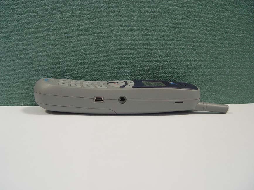
Click to zoom
Application Details
- Equipment Class
- PCE - PCS Licensed Transmitter held to ear
- Date of Grant
- Apr 25, 2006
- Application Purpose
- Original Equipment
- Date of Application
- Apr 25, 2006
- Equipment Note
- PCS CDMA Phone
- Frequency Range
- 1851.25000000 - 1908.75000000
- Company
- Telian Corporation
- Country
- South Korea
Documents & Files
Document Text
Text extracted from the exhibit documents filed with the FCC. Open a document above to read the original.
Users Manual
(Back cover) All other product or service names are the property of their respective owners. The information contained in this user’s guides is believed to be correct at the time of printing. We reserve the right to change or modify any information or specifications without notice. The contents of this user’s guides are provided “as is.” Except as required by applicable law, no warranties of any kind, either express or implied, including, but not limited to, the implied warranties of merchantability and fitness for a particular purpose, are made in relation to the accuracy, reliability, or contents of this guide. © Copyright 2005, BRIGHTSTAR Corp., All rights reserved. 1 FCS 8010 (AVVIO 8100) REV. 1 (12/02/2005) 2 (This page is left blank intentionally) 3 WELCOME Congratulations on your purchase of an Avvio 8100 product! Please retain your original dated sales receipt for your records. For warranty service of your Avvio product you will need to provide a copy of your dated sales receipt to confirm warranty status. Please read important safety instructions on page 7 before use. Read and understand all instructions before use. Please retain this guide for future reference. 4 CONTENTS 1. SAFETY INFORMATION 2. PREPARE YOUR PHONE FOR USE 2.1 Install the battery 2.2 Charge the battery 2.2.1 Base 2.2.2 Handy 3. FEATURE HIGHLIGHTS 4. ABOUT THE PHONE 4.1 Name and function 4.2 Key functions 4.3 Display indicators 4.3.1 Idle screen 4.3.2 Scroll Bar 4.4 Icons 5. BASIC OPERATIONS 5.1 Power ON and OFF 5.2. Make a call 5.3 Answer a call 5.4 Adjust the volume 5.5 Redial the recent call number 5.6 Caller ID 5.7 Out of Range display and warning tone 5.8 Paging 5.9 Handy and Base ID settings 5.10 SMS and Voice mail 5 6. USE PHONE MENUS 6.1 Navigate menus 6.1.1 Scroll through menus 6.1.2 Use a shortcut 6.1.3 Exit menu levels 6.2 List of Menus 7. ENTER LETTERS AND NUMBERS 7.1 Enter Letters 7.1.1 Edit name 7.1.2 Change case of letters and numbers 8. USE THE PHONE BOOK 8.1 About the phone book 8.2 Add a new phone book Entry 8.3 Edit Entry 8.4 Search Entry 8.5 Search Name 8.6 Erase 8.7 My Phone Number 9. USE CALL LOGS 9.1 Check Missed / Received / Dialed Calls 9.2 Erase Logs 9.3 Call Duration 10. USE SMS (SHORT MESSAGE SERVICE) 10.1 Send a Text Message 10.2 View Inbox / Outbox 10.3 Erase a message 10.4 Message Settings 6 10.5 Use Voice mail 11. SOUND MENU 11.1 Set Ring Type 11.2 Set Ring Tone 11.3 Set Ring Volume 11.4 Set Key Tone 11.5 Set Sound Setting 11.6 Set Alarm 12. USER SETTINGS 12.1 Set Auto Redial 12.2 Set Lift Answer 12.3 Set One Touch 12.4 Set Voice Privacy 12.5 Set Back-Light 12.6 Set LCD Contrast 12.7 Set Language 12.8 Set Data Service 13. SECURITY 13.1 Set Auto Lock 13.2 Set Change Code 13.3 Set Restrict 13.4 Set Reset 14. REFERENCE INFORMATION 14.1 Emergency Calls 14.1.1 Make an emergency call 14.2 Troubleshooting 14.2.1 No Service 14.2.2 What if the call does not go through? 7 15. TECHNICAL INFORMATION 1 SAFETY INFORMATION SAFETY INFORMATION FOR FIXED PHONES IMPORTANT INFORMATION ON SAFE AND EFFICIENT OPERATION. READ THIS INFORMATION BEFORE USING YOUR PHONE. EXPOSURE TO RADIO FREQUENCY (RF) ENERGY Your phone contains a transmitter and a receiver. When it is ON, it receives and also sends out radio frequency (RF) signals. When you communicate with your phone, the system handling your call controls the power level at which your phone transmits. Your AVVIO phone is designed to comply with local regulatory requirements in your country concerning exposure of human beings to RF energy. OPERATIONAL PRECAUTIONS To assure optimal phone performance and make sure human exposure to RF energy is within the guidelines set forth in the relevant standards; always adhere to the following procedures. EXTERNAL ANTENNA CARE Use only the supplied BRIGHSTAR approved antenna. Unauthorized antennas, modifications, or attachments could damage the phone. Do NOT hold the antenna when the phone is IN USE. Holding the antenna affects call quality and may cause the phone to operate at a higher power level than needed. In addition, use of unauthorized antennas may result in non-compliance with the local regulatory requirements in your country. PHONE OPERATION When placing or receiving a phone call, hold your phone as you would a wireline telephone. 8 DATA OPERATION When using any data feature of the phone, with or without an accessory cable, position the phone and its antenna at least 1 inch (2.5 centimeters) from your body. APPROVED ACCESSORIES Use of accessories not approved by BRIGHTSTAR, including but not limited to batteries and antennas, may cause your phone to exceed RF energy exposure guidelines. RF ENERGY INTERFERENCE / COMPATIBILITIES Note: Nearly every electronic device is susceptible to RF energy interference from external sources if in adequately shielded, designed, or otherwise configured for RF energy compatibility. In some circumstances your phone may cause interference. Facilities Turn off your phone in any facility where posted notices instruct you to do so. These facilities may include hospitals or health care facilities that may be using equipment that is sensitive to external RF energy. MEDICAL DEVICE Pacemakers Pacemaker manufacturers recommend that a minimum separation of 6 inches (15centimeters) be maintained between a handheld wireless phone and a pacemaker. Persons with pacemakers should: • Always keep the phone more than 6 inches (15 centimeters) from your pacemaker when the phone is turned ON. • Not carry the phone in the breast pocket • Use the ear opposite the pacemaker to minimize the potential for interference. • Turn OFF the phone immediately if you have any reason to suspect that interference is taking place. 9 Hearing Aids Some digital wireless phones may interfere with some hearing aids. In the event of such interference, you may want to consult your hearing aid manufacturer to discuss alternatives. Other Medical Devices If you use any other personal medical device, consult the manufacturer…
Text truncated - open the document above for the full version.
Cover Letter(s)
4th ~ 7th Fl. Namjeun Bldg. 53-3 Haan-Dong Gwangmyung-Si, Kyunggido-Do, 423-060, Korea Mar 28, 2006 Federal Communications Commission Equipment Authorization Branch 7435 Oakland Mills Road Columbia, MD 21046 LETTER OF AUTHORIZATION To whom it may concern: We, the undersigned, hereby authorize DIGITAL EMC Co., Ltd., to act on our behalf in all manners relating to application for equipment authorization for FCC ID: NPQFCS8010. including signing of all documents relating to these matters. Any and all acts carried out by DIGITAL EMC Co., Ltd., on our behalf shall have the same affect as acts of our own. This authorization is valid until further written notice from Telian Corporation. Sincerely, W.H WHANG/Senior Engineer
Cover Letter(s)
4th ~ 7th Fl. Namjeun Bldg. 53-3 Haan-Dong Gwangmyung-Si, Kyunggido-Do, 423-060, Korea Mar 28, 2006 Federal Communications Commission Equipment Authorization Branch 7435 Oakland Mills Road Columbia, MD 21046 In re : Telian Corporation FCC ID : NPQFCS8010 Request for Confidentiality Gentlemen: In accordance with 0.459 of CFR 47, Telian Corporation hereby requests confidentiality of the Block diagram, Schematics, Parts list, Turn up procedure and Operational description of the attached test report. These documents contain detailed system and equipment description and related information about the product which Telian Corporation considers to be proprietary, confidential, and a custom design and, otherwise, would not release to the general public. Since this design is a basis from which future technological products will evolve, Telian Corporation. considers that this information would be of benefit to its competitors, and that the disclosure of the information in these documents would give competitors an unfair advantage in the market. Sincerely, W.H WHANG/Senior Engineer
Cover Letter(s)
4th ~ 7th Fl. Namjeun Bldg. 53-3 Haan-Dong Gwangmyung-Si, Kyunggido-Do, 423-060, Korea Mar 28, 2006 Federal Communications Commission Equipment Authorization Branch 7435 Oakland Mills Road Columbia, MD 21046 In re : Telian Corporation FCC ID : NPQFCS8010 Request for Short-Term Confidentiality To Whom It May Concern: In accordance with 0.459 of CFR 47, Telian Corporation requests short-term Confidentiality of following sections of this application for a period of 45 days after grant is issued. Test setup photos External photos except the external photos in the SAR report Internal photos, and User’s manual These documents contain detailed system and equipment descriptions and related information about the product, which Telian Corporation considers to be proprietary, confidential, and a custom design and otherwise, would not release to the general public. Since this design is a basis from which future technological products will evolve, Telian Corporation feels that this information would be of benefit to its competitors, and that the disclosure of the information in these documents would give our competitors an unfair advantage in the market. Sincerely, W.H WHANG/Senior Engineer
Cover Letter(s)
From: Generic Office of Engineering Technology [mailto:[email protected]] Sent: Monday, April 24, 2006 4:23 PM To: [email protected] Subject: Response to Inquiry to FCC (Tracking Number 321500) Inquiry: FCC, I am reviewing another Cell/PCS CDMA2000 1x bar-type handset with stub antenna. During testing the laboratory investigated the combinations of RC''''''''s and SO''''''''s to determine the worst case power (very little variance). I have reviewed this in accordance with the guides from the 3G Roundtable presentation materials. Please provide any further guidance needed for TCB review. Best regards, Chris Harvey [email protected] 410-750-0860 MT#19664 ---Reply from Customer on 04/18/2006--- Although it appears as though the inquiry's are the same, each one is for a separate application. The attachments submitted with each inquiry relates to a specific handset. Please contact me if you have any questions. Chris Harvey 443-622-3300 Response: Thank you for your inquiry - FCC is continuing to investigate and update measurement and TCB review & approval procedures for 3G devices, and plans to circulate revised versions soon. Meanwhile, please ensure TCB filings are consistent with present version of CDMA-2000 guidance - please see also attachment and comments for similar data set in KDB inq. no. 802903. Do not reply to this message. Please select the Reply to an Inquiry Response link from the OET Inquiry System to add any additional information pertaining to this inquiry. From: Generic Office of Engineering Technology [mailto:[email protected]] Sent: Monday, April 24, 2006 3:53 PM To: [email protected] Subject: Response to Inquiry to FCC (Tracking Number 802903) Inquiry: FCC, I am reviewing another Cell/PCS CDMA2000 1x clamshell handset with extending antenna. During testing the laboratory investigated the combinations of RC''''s and SO''''s to determine the worst case power (very little variance). I have reviewed this in accordance with the guides from the 3G Roundtable presentation materials. Please provide any further guidance needed for TCB review. Best regards, Chris Harvey [email protected] 410-750-0860 AN06T5640 Response: Thank you for your inquiry - FCC is continuing to investigate and update measurement and TCB review & approval procedures for 3G devices, and plans to circulate revised versions soon. Meanwhile, please ensure TCB filings are consistent with guidance in attached. Other specific comments are below. Below are some comments about attachment page designated "CDMA 384," which are power test results to select and support SAR channels tested and results - please apply similar concepts in other data sets. Certification application filings may also need to address other aspects from CDMA-2000 transmitter set-up guidance even if not discussed below. -------------------------------------------------------------------------------------- FYI note that summary table on 3rd page of CDMA 2000 Tx Config Info package is for info purposes, and to show feasible channel configurations, but may not necessary or appropriate to repeat this table in all filings. Table is unclear about meaning of "Nothing" - filing should explain. As given in Tx Config, "For systems with P_REV equal to 6 or higher, the service option described by 3GPP2 C.S0013 shall use service option number 55 and is called Service Option 55." All CDMA phones use new version vocoder, therefore SO1, SO3, and other voice modes do not apply for SAR testing (power drops out). SO 032768 is a proprietary mode - for uniformity in processing, in general! TCB filings should avoid proprietary modes. RC5 configurations seem to indicate possible set-up problems, because to our knowledge 3x simulators are not yet available. If device was somehow forced into that mode, it is not likely to be valid operation. Please review and apply recommended SO set-ups in FCC guidance document. -------------------------------------------------------------------------------------- Do not reply to this message. Please select the Reply to an Inquiry Response link from the OET Inquiry System to add any additional information pertaining to this inquiry.
External Photos
FCC ID: NPQFCS8010 Copyright Ⓒ 2006, DIGITAL EMC Co., Ltd. View 1 FCC ID: NPQFCS8010 Copyright Ⓒ 2006, DIGITAL EMC Co., Ltd. View 2 FCC ID: NPQFCS8010 Copyright Ⓒ 2006, DIGITAL EMC Co., Ltd. View 3
ID Label/Location Info
FCC ID : NPQFCS8010 Copyright ○ c 2006, DIGITAL EMC Co., Ltd. FCC ID SAMPLE LABEL & LOCATION LABELLING REQUIREMENTS PER §2.925 The Label shown shall be permanently affixed at a conspicuous location on the device and be readily visible to the user at the time of purchase Note: 1. The label generally is located underneath a back door of the phone. 2. Because The device is so small that it is not practicable to place the statement specified under 15.19 statement request, the information required by this paragraph shall be placed in a prominent location in the user's manual. (SEE NEXT PAGE)
Internal Photos
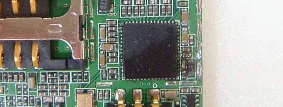
FCC ID: NPQFCS8010 Copyright Ⓒ 2006, DIGITAL EMC Co., Ltd. View 1 FCC ID: NPQFCS8010 Copyright Ⓒ 2006, DIGITAL EMC Co., Ltd. View 2 FCC ID: NPQFCS8010 Copyright Ⓒ 2006, DIGITAL EMC Co., Ltd. View 3 FCC ID: NPQFCS8010 Copyright Ⓒ 2006, DIGITAL EMC Co., Ltd. View 4 FCC ID: NPQFCS8010 Copyright Ⓒ 2006, DIGITAL EMC Co., Ltd. View 5(900MHz RX Module) FCC ID: NPQFCS8010 Copyright Ⓒ 2006, DIGITAL EMC Co., Ltd. View 6(900MHz RX Module) FCC ID: NPQFCS8010 Copyright Ⓒ 2006, DIGITAL EMC Co., Ltd. View 7 FCC ID: NPQFCS8010 Copyright Ⓒ 2006, DIGITAL EMC Co., Ltd. View 8
Operational Description
APPLICANT: TELIAN Corp. FCC ID: NPQFCS8010 INFORMATION REGARDING ELECTRONIC SERIAL NUMBER (ESN) This cellular transceiver uses a microprocessor to control its call processing operation. This microprocessor accesses a programmable memory area, which is used to store an encrypted data block that contains the Electronic Serial Number (ESN). A proprietary scheme is used to create this data block whereby it is encrypted using methods similar to known public key cryptography methods. It is emphasized that the method used is similar to but different from these known methods and the actual method used is kept proprietary to provide the essential security for the ESN. Access is controlled to both the method of encryption and to the production/repair equipment that has the ability to program the encrypted data block.
Operational Description
FCC ID: NPQFCS8010 Protocol Reversion Number: 6 Max Conducted Output PWR of various operation modes of FCS-8010 Conducted Output Power(dBm) Radio Configuration Service Option Low Channel(25) 1851.25MHz Mid Channel(600) 1880.00MHz High Channel(1175) 1908.75MHz F1R1 SO2(Loopback) 23.6 23.5 23.4 F2R2 SO9(Loopback) 23.6 23.4 23.4 9.6 Kbps 23.5 23.4 23.3 19.2 Kbps 23.6 23.5 23.3 38.4 Kbps 23.6 23.5 23.3 76.8 Kbps 23.6 23.5 23.4 F3R3 SO55 (Loopback) 153.6 Kbps 23.6 23.5 23.4 9.6 Kbps 23.6 23.5 23.5 19.2 Kbps 23.5 23.5 23.4 38.4 Kbps 23.6 23.4 23.4 76.8 Kbps 23.5 23.4 23.4 F4R3 SO55 (Loopback) 153.6 Kbps 23.6 23.5 23.5 14.4 Kbps 23.5 23.5 23.5 28.8 Kbps 23.5 23.4 23.5 57.6 Kbps 23.6 23.4 23.5 115.2 Kbps 23.6 23.5 23.5 F5R4 SO55 (Loopback) 230.4 Kbps 23.6 23.5 23.5 TEST MODE 23.7 23.6 23.6
Operational Description
Copyright ○ c 2006, DIGITAL EMC Co., Ltd. DIPOLE CALIBRATION Copyright ○ c 2006, DIGITAL EMC Co., Ltd. 1. 1900 Dipole Calibration
Operational Description
G Copyright ̺ c 2006, DIGITAL EMC Co., Ltd. PROBE CALIBRATION
Operational Description
DIGITAL EMC CO., LTD DUT: Dipole 1900 MHz; Type: D1900V2; Serial: D1900V2 - SN:5d029 Communication System: CW; Frequency: 1900 MHz;Duty Cycle: 1:1 Medium parameters used: f = 1900 MHz; σ = 1.39 mho/m; ε r = 40.5; ρ = 1000 kg/m 3 Phantom section: Flat Section DASY4 Configuration: Probe: ET3DV6 - SN1703; ConvF(5.27, 5.27, 5.27); Calibrated: 2005-03-24; Electronics: DAE3 Sn519 Phantom: SAM 1800/1900 MHz; Type: SAM; Serial: TP-1224 Measurement SW: DASY4, V4.5 Build 19; Postprocessing SW: SEMCAD, V1.8 Build 145 Test Date: 2006-03-09; Ambient Temp: 21.0; Tissue Temp: 20.5 Dipole Validation Area Scan (41x71x1): Measurement grid: dx=15mm, dy=15mm Zoom Scan (7x7x7)/Cube 0: Measurement grid: dx=5mm, dy=5mm, dz=5mm Power Drift = -0.060 dB Peak SAR (extrapolated) = 20.0 W/kg SAR(1 g) = 10.6 mW/g; SAR(10 g) = 5.36 mW/g 0 dB = 12.0mW/g DIGITAL EMC CO., LTD DUT: FCS-8010; Type: CDMA single Band Communication System: FCC_PCS; Frequency: 1851.25 MHz;Duty Cycle: 1:1 Medium parameters used: f = 1851.25 MHz; σ = 1.34 mho/m; ε r = 40.7; ρ = 1000 kg/m 3 Phantom section: Right Section DASY4 Configuration: Probe: ET3DV6 - SN1703; ConvF(5.27, 5.27, 5.27); Calibrated: 2005-03-24; Electronics: DAE3 Sn519 Phantom: SAM 1800/1900 MHz; Type: SAM; Serial: TP-1224 Measurement SW: DASY4, V4.5 Build 19; Postprocessing SW: SEMCAD, V1.8 Build 145 Date: 2006-03-09; Ambient Temp: 21.0; Tissue Temp:20.5 Right Touch CDMA Ch.25, Ant Fixed, Standard Battery Area Scan (61x101x1): Measurement grid: dx=15mm, dy=15mm Zoom Scan (7x7x7)/Cube 0: Measurement grid: dx=5mm, dy=5mm, dz=5mm Power Drift = -0.229 dB Peak SAR (extrapolated) = 1.25 W/kg SAR(1 g) = 0.773 mW/g; SAR(10 g) = 0.452 mW/g 0 dB = 0.849mW/g DIGITAL EMC CO., LTD DUT: FCS-8010; Type: CDMA single Band Communication System: FCC_PCS; Frequency: 1851.25 MHz;Duty Cycle: 1:1 Medium parameters used: f = 1851.25 MHz; σ = 1.34 mho/m; ε r = 40.7; ρ = 1000 kg/m 3 Phantom section: Right Section DASY4 Configuration: Probe: ET3DV6 - SN1703; ConvF(5.27, 5.27, 5.27); Calibrated: 2005-03-24; Electronics: DAE3 Sn519 Phantom: SAM 1800/1900 MHz; Type: SAM; Serial: TP-1224 Measurement SW: DASY4, V4.5 Build 19; Postprocessing SW: SEMCAD, V1.8 Build 145 Date: 2006-03-09; Ambient Temp: 21.0; Tissue Temp:20.5 Right Touch CDMA Ch.25, Ant Fixed, Standard Battery Area Scan (61x101x1): Measurement grid: dx=15mm, dy=15mm Zoom Scan (7x7x7)/Cube 1: Measurement grid: dx=5mm, dy=5mm, dz=5mm Power Drift = -0.229 dB Peak SAR (extrapolated) = 0.802 W/kg SAR(1 g) = 0.555 mW/g; SAR(10 g) = 0.345 mW/g 0 dB = 0.590mW/g DIGITAL EMC CO., LTD DUT: FCS-8010; Type: CDMA single Band Communication System: FCC_PCS; Frequency: 1880 MHz;Duty Cycle: 1:1 Medium parameters used: f = 1880 MHz; σ = 1.37 mho/m; ε r = 40.6; ρ = 1000 kg/m 3 Phantom section: Right Section DASY4 Configuration: Probe: ET3DV6 - SN1703; ConvF(5.27, 5.27, 5.27); Calibrated: 2005-03-24; Electronics: DAE3 Sn519 Phantom: SAM 1800/1900 MHz; Type: SAM; Serial: TP-1224 Measurement SW: DASY4, V4.5 Build 19; Postprocessing SW: SEMCAD, V1.8 Build 145 Date: 2006-03-09; Ambient Temp: 21.0; Tissue Temp:20.5 Right Touch CDMA Ch.600, Ant Fixed, Standard Battery Area Scan (61x101x1): Measurement grid: dx=15mm, dy=15mm Zoom Scan (7x7x7)/Cube 0: Measurement grid: dx=5mm, dy=5mm, dz=5mm Power Drift = -0.186 dB Peak SAR (extrapolated) = 1.41 W/kg SAR(1 g) = 0.870 mW/g; SAR(10 g) = 0.507 mW/g 0 dB = 0.948mW/g DIGITAL EMC CO., LTD DUT: FCS-8010; Type: CDMA single Band Communication System: FCC_PCS; Frequency: 1880 MHz;Duty Cycle: 1:1 Medium parameters used: f = 1880 MHz; σ = 1.37 mho/m; ε r = 40.6; ρ = 1000 kg/m 3 Phantom section: Right Section DASY4 Configuration: Probe: ET3DV6 - SN1703; ConvF(5.27, 5.27, 5.27); Calibrated: 2005-03-24; Electronics: DAE3 Sn519 Phantom: SAM 1800/1900 MHz; Type: SAM; Serial: TP-1224 Measurement SW: DASY4, V4.5 Build 19; Postprocessing SW: SEMCAD, V1.8 Build 145 Date: 2006-03-09; Ambient Temp: 21.0; Tissue Temp:20.5 Right Touch CDMA Ch.600, Ant Fixed, Standard Battery Area Scan (61x101x1): Measurement grid: dx=15mm, dy=15mm Zoom Scan (7x7x7)/Cube 1: Measurement grid: dx=5mm, dy=5mm, dz=5mm Power Drift = -0.186 dB Peak SAR (extrapolated) = 0.878 W/kg SAR(1 g) = 0.602 mW/g; SAR(10 g) = 0.374 mW/g 0 dB = 0.643mW/g DIGITAL EMC CO., LTD DUT: FCS-8010; Type: CDMA single Band Communication System: FCC_PCS; Frequency: 1908.75 MHz;Duty Cycle: 1:1 Medium parameters used: f = 1908.75 MHz; σ = 1.4 mho/m; ε r = 40.5; ρ = 1000 kg/m 3 Phantom section: Right Section DASY4 Configuration: Probe: ET3DV6 - SN1703; ConvF(5.27, 5.27, 5.27); Calibrated: 2005-03-24; Electronics: DAE3 Sn519 Phantom: SAM 1800/1900 MHz; Type: SAM; Serial: TP-1224 Measurement SW: DASY4, V4.5 Build 19; Postprocessing SW: SEMCAD, V1.8 Build 145 Date: 2006-03-09; Ambient Temp: 21.0; Tissue Temp:20.5 Right Touch CDMA Ch.1175, Ant Fixed, Standard Battery Area Scan (61x101x1): Measurement grid: dx=15mm, dy=15mm Zoom Scan (7x7x7)/Cube 0: Measurement grid: dx=5mm, dy=5mm, dz=5mm Power Drift = -0.154 dB Peak SAR (extrapolated) = 1.34 W/kg SAR(1 g) = 0.854 mW/g; SAR(10 g) = 0.504 mW/g 0 dB = 0.926mW/g DIGITAL EMC CO., LTD DUT: FCS-8010; Type: CDMA single Band Communication System: FCC_PCS; Frequency: 1908.75 MHz;Duty Cycle: 1:1 Medium parameters used: f = 1908.75 MHz; σ = 1.4 mho/m; ε r = 40.5; ρ = 1000 kg/m 3 Phantom section: Right Section DASY4 Configuration: Probe: ET3DV6 - SN1703; ConvF(5.27, 5.27, 5.27); Calibrated: 2005-03-24; Electronics: DAE3 Sn519 Phantom: SAM 1800/1900 MHz; Type: SAM; Serial: TP-1224 Measurement SW: DASY4, V4.5 Build 19; Postprocessing SW: SEMCAD, V1.8 Build 145 Date: 2006-03-09; Ambient Temp: 21.0; Tissue Temp:20.5 Right Touch CDMA Ch.1175, Ant Fixed, Standard Battery Area Scan (61x101x1): Measurement grid: dx=15mm, dy=15mm Zoom Scan (7x7x7)/Cube 1: Measurement grid: dx=5mm, dy=5mm, dz=5mm Power Drift = -0.154 dB Peak SAR (extrapolated) = 0.860 W/kg SAR(1 g) = 0.601 mW/g; SAR(10 g) = 0.375 mW/g 0 dB = 0.644mW/g DIGITAL EMC CO., LTD DUT: FCS-8010; Type: CDMA single Band …
Text truncated - open the document above for the full version.
RF Exposure Info
DEMC#DR50110604A Copyright ○ c 2006, DIGITAL EMC Co., Ltd. Page 1 of 22 683-3, Yubang-Dong, Yongin-Si, Kyunggi-Do, Korea. 449-080 Tel: +82-31-321-2664 Fax: +82-31-321-1664 http://www.digitalemc.com SAR TEST REPORT Dates of Tests: March 9, 2006 Test Report S/N:DR50110604A Test Site : DIGITAL EMC CO., LTD. FCC ID APPLICANT FCC Classification: Licensed Portable Transmitter Held to Ear (PCE) EUT Type: Single-Band CDMA Phone Model Name FCS8010 Test Device Serial No.: Identical prototype TX Frequency Range: 1851.25 ~1908.75 MHz (CDMA) RX Frequency Range: 1931.25 ~1988.75 MHz (CDMA) Max. RF Output Power: 0.308 W EIRP CDMA 1900 (24.88dBm) Max. SAR Measurement: 1.450 mW/g PCS1900 Head SAR 0.561 mW/g PCS1900 Body SAR Application Type: Certification Rule Part(s): §2.1093; FCC/OET Bulletin Supplement C[July 2001] Data of issue: April 3, 2006 Tested by : Reviewed by : Sun-Kyu Ryu (Engineer) Harvey Sung (Chief Engineering Director) This wireless portable device has been shown to be capable of compliance for localized specific absorption rate (SAR) for uncontrolled environment/general population exposure limits specified in ANSI/IEEE Std. C95.1-1992 and had been tested in accordance with the measurement procedures specified in FCC/OET Bulletin 65 Supplement C (2001) and IEEE Std. 1528-2003. I attest to the accuracy of data. All measurements reported herein were performed by me or were made under my supervision and are correct to the best of my knowledge and belief. I assume full responsibility for the completeness of these measurements and vouch for the qualifications of all persons taking them. NPQFCS8010 Telian Corporation DEMC#DR50110604A Copyright ○ c 2006, DIGITAL EMC Co., Ltd. Page 2 of 22 1. INTRODUCTION ...................................................................................................... 3 SAR DEFINITION .................................................................................................... 3 2. SAR MEASUREMENT SETUP......................................................................................... 4 Robotic System.......................................................................................................... 4 System Hardware ....................................................................................................... 4 System Electronics...................................................................................................... 4 3. DASY4 E-FIELD PROBE SYSTEM................................................................................... 5 Probe Measurement System......................................................................................... 5 Probe Specifications .................................................................................................... 5 4. Probe Calibration Process............................................................................................ 6 Dosimetric Assessment Procedure.................................................................................. 6 Free Space Assessment ............................................................................................... 6 Temperature Assessment ............................................................................................ 6 5. PHANTOM & EQUIVALENT TISSUES.............................................................................. 7 SAM Phantom ........................................................................................................... 7 Brain & Muscle Simulating Mixture Characterization ....................................................... 7 Device Holder for Transmitters..................................................................................... 7 6. TEST SYSTEM SPECIFICATIONS.................................................................................. 8 Automated Test System Specifications.......................................................................... 8 7. DOSIMETRIC ASSESSMENT & PHANTOM SPECS ........................................................... 9 Measurement Procedure............................................................................................. 9 Specific Anthropomorphic Mannequin (SAM) Specifications.............................................. 9 8. DEFINITION OF REFERENCE POINTS .......................................................................... 10 EAR Reference Point................................................................................................... 10 Handset Reference Points............................................................................................ 10 9. TEST CONFIGURATION POSITIONS ............................................................................. 11 Positioning for Cheek/Touch ........................................................................................ 11 Positioning for Ear /15° Tilt ......................................................................................... 12 Body Holster /Belt Clip Configurations .......................................................................... 13 10. ICNIRP GUIDELINES RF EXPOSURE LIMITS.................................................................. 14 Uncontrolled Environment ........................................................................................... 14 Controlled Environment........................................................................................ ....... 14 11. MEASUREMENT UNCERTAINTIES............................................................................... 15 SAR Measurement Uncertainties .................................................................................. 15 12. SYSTEM VERIFICATION........................................................................................... 16 Tissue Verification...................................................................................................... 16 Test System Verification.................................................…
Text truncated - open the document above for the full version.
Test Report
DEMC#DR50110604F Copyright ○ c 2006, DIGITAL EMC Co., Ltd. Page 1 of 29 683-3, Yubang-Dong, Yongin-Si, Kyunggi-Do, Korea. 449-080 Tel: +82-31-321-2664 Fax: +82-31-321-1664 http://www.digitalemc.com CERTIFICATE OF COMPLIANCE FCC Part 24 Certification Dates of Tests: March 13 ~ 17, 2006 Test Report S/N:DR50110604F Test Site : DIGITAL EMC CO., LTD. Model No. APPLICANT Classification: Licensed Portable Transmitter Held to Ear (PCE) FCC Rule Part(s): §24(E), §2 EUT Type: Single-Band PCS Phone (CDMA) Model name: FCS-8010 Add Model name Avvio 8100 Serial number: Identical prototype TX Frequency Range: 1851.25 ~ 1908.75 MHz RX Frequency Range: 1931.25 ~ 1988.75 MHz Max. RF Output Power: 0.308 W EIRP CDMA1900 (24.88dBm) Max. SAR Measurement: 1.450W/kg CDMA1900 Head SAR 0.561W/kg CDMA1900 Body SAR Date of Issue: April 11, 2006 NPQFCS8010 Telian Corporation DEMC#DR50110604F Copyright ○ c 2006, DIGITAL EMC Co., Ltd. Page 2 of 29 TABLE OF CONTENTS ATTACHMENT: CONFIDENTIALITY LETTER(S) ATTACHMENT: AUTHORIZATION LETTER ATTACHMENT: TEST REPORT 1 SCOPE 3 2 INTRODUCTION 4 3 TEST REPORT 5 3.1 SUMMARY OF TEST 5 3.2 REQUIREMENTS 6 3.2.1 POWER OUTPUT 6 3.2.2 OCUPIED BANDWIDTH 10 3.2.3 OCCUPIED BANDWIDTH EMISSION LIMIT 13 3.2.4 SPURIOUS EMISSION AT ANT. TERMINAL 15 3.2.5 FIELD STRENGTH OF SPURIOUS RADIATION 19 3.2.6 FREQUENCY STABILITY / TEMPERATURE VARIATION 23 4 TEST EQUIPMENT 26 5 EMISSION DESIGNATOR 28 6 CONCLUSION 29 ATTACHMENT: FCC ID LABEL & LOCATION ATTACHMENT: TEST SETUP PHOTOGRAPHS ATTACHMENT: EXTERNAL PHOTOGRAPHS ATTACHMENT: INTERNAL PHOTOGRAPHS ATTACHMENT: BLOCK DIAGRAM(S) ATTACHMENT: SCHEMATIC DIAGRAM(S) ATTACHMENT: OPERATIONAL / CIRCUIT DESCRIPTION ATTA…
Text truncated - open the document above for the full version.
Contact Information
Applicant
Wayne Hwang(CTO)
Test Firm
DT&C Co.,Changho Lee
Technical Specifications
| # | Rule Parts | Frequency Range | Power Output | Emission | Tolerance |
|---|---|---|---|---|---|
| 1 | 24E | 1.85 GHz - 1.91 GHz | 307.00 mW | 1M27F9W | 2.5000000000 ppm |
Other Applications from Telian Corporation
NPQK1000
Jan 24, 2008GSM850/PCS1900 Dual Band GPRS Terminal Equip. w/BT
Equipment Class
PCE - PCS Licensed Transmitter held to ear
NPQI405
Aug 06, 2007GSM850 / PCS1900 Dual Band GPRS Terminal with BT
Equipment Class
DSS - Part 15 Spread Spectrum Transmitter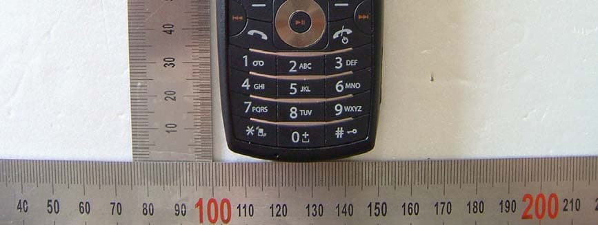
NPQI170
Jun 05, 2007GSM850/PCS1900 Dual Band GPRS Terminal with BT
Equipment Class
PCE - PCS Licensed Transmitter held to ear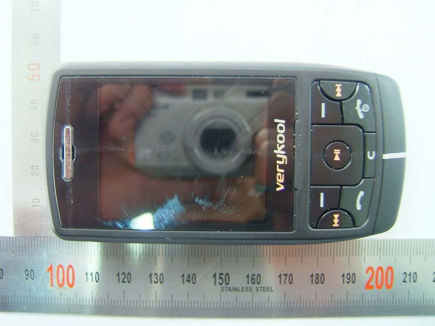
NPQMGQ9180
Mar 13, 2007Quad-Band GSM/GPRS Handset with Bluetooth
Equipment Class
DSS - Part 15 Spread Spectrum Transmitter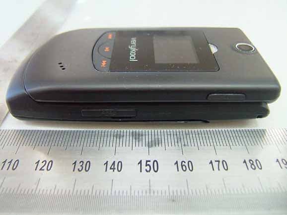
NPQMGQ7180
Feb 27, 2007Quad-Band GSM/GPRS Handset with Bluetooth
Equipment Class
PCE - PCS Licensed Transmitter held to ear