NPQI170GSM850/PCS1900 Dual Band GPRS Terminal with BT
Telian Corporation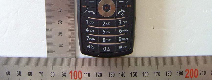
Click to zoom
Application Details
- Equipment Class
- PCE - PCS Licensed Transmitter held to ear
- Date of Grant
- Jun 05, 2007
- Application Purpose
- Original Equipment
- Date of Application
- Jun 05, 2007
- Equipment Note
- GSM850/PCS1900 Dual Band GPRS Terminal with BT
- Frequency Range
- 1850.20000000 - 1909.80000000
- Company
- Telian Corporation
- Country
- South Korea
Documents & Files
Document Text
Text extracted from the exhibit documents filed with the FCC. Open a document above to read the original.
Users Manual
I170 Phone User’s Manual 2 About this manual Welcome to the I170 Phone. This Phone comes with two parts. ‘Before you start’ ‘Operation Instruction’ Before using your I170 Phone, read ‘Before you start’ for overview of features, basic setup, and other important details. After you have become familiarized with its basic functionality, refer to the operation Instruction for detailed features, less common tasks, and for maintaining your I170 Phone. These manuals can also serve as a source of information if you have problems operating your I170 Phone. 3 I. Before you start A. FEATURES 1.Unpacking 2.Phone Layout 3. Display Layout 4. Battery 5. SIM Card 6. T-Flash 7. Headset 8. USB Cable B. Basic usages 1. Power On/Off 2. Call Function 3. Multimedia Function 4. Text Input mode 5. Phone Book 4 II. Operation Instruction A. Menu Operation 1. Phone Book 2. Message Center 3. Call Histroy 4. Settings 5. Multimedia 6. Fun & Games 7. User Profiles 8. Organizer 9. Services B. Trouble Shooting C. Safety Information D. Glossary 5 I. Before you start I170 Phone 6 A. Features 1. Unpacking Your package list is as shown below Handset Manual Travel Adaptor Earphone USB Cable (Optional) 2. Phone Layout The following illustration shows the main elements of your phone. 2.1 LCD The Main LCD is CSTN LCD and has 65K colors You can be enjoy the more clear LCD color with your I170 phone 2.2 Camera You can take a photo with I170’s embedded digital camera. I170 has 300k pixels camera module, you can enjoy highly qualify digital photo with your I170 phone. 2.3 Bar Type I170 is Bar type phone. 7 2.4 Keys Description Function Keys Left Soft Key [Basic Function] Performs the functions indicated by the text in the left-bottom line of the display screen. Usually works as ‘selection’ key [Idle Mode] Enter main menu Right Soft key [Basic Function] Performs the functions indicated by the text in the right-bottom line of the display screen. Usually works as ‘backward’ key [Idle Mode] Enter Phonebook list menu Makes or answers a call. In the idle mode, launches the call log menu. Ends a call. Also switches the phone on or off when pressed and held. In the menu, returns to the idle mode or cancels your input. Navigation Keys [Idle Mode] Enter WAP browser mode (press and hold) Left soft key function (short press) [Basic Function] move the cursor or selection bar up (Text edit mode or menu mode) [Idle Mode] Audio Player [Camera Mode] Magnify the image (Digital Zoom Function) [MP3 Mode] Play & Pause MP3 file 8 [Basic Function] move the cursor or selection down (Text edit mode or menu mode) [Idle Mode] Alarm Menu [Camera Mode] Reduce the image (Digital Zoom Function) [MP3 Mode] Stop playing MP3 file [Basic Function] move the cursor or selection left (Text edit mode or menu mode) [Idle Mode] User Profile Menu [Camera Mode] Adjust EV Level [MP3 Mode] Go to previous MP3 file [Basic Function] move the cursor or selection right (Text edit mode or menu mode) [Idle Mode] Tone Setup Menu [Camera Mode] Adjust EV Level [MP3 Mode] Go to next MP3 file 9 Alphanumeric Keys [Press] Enter number and string * key : Enter ‘+’ (international call) by using Multitap Input Method. [Press and Hold] # key : On and Off silent mode [Video Play Mode] Wide screen view Side Keys [Basic Function] move the cursor or selection bar up in menu mode [Idle Mode] Increase the key-tone volume [MP3 Mode] Increase the volume [Basic Function] move the cursor or selection down (Text edit mode or menu mode) [Idle Mode] Decrease the key-tone volume [MP3 Mode] Decrease the volume [Short Press] Enter the Camera Mode [Press and Hold] Enter the Take Video Record Mode 10 3. Display Layout 3.1 Display Screen Å Fixed Icon Area Å Network Status Area Å User Setting Screen Area Å Time & Date Area Å Soft Key Area 3.1.1 Fixed Icon Area: 8 fixed icons are displayed indicating the phone status. 3.1.2 Network Status Area: Network name registered is displayed. If there is no GSM network coverage, No Service is displayed. If you are in the coverage area of a GSM network but you are not allowed to register to the network, Emergency is displayed. 3.1.3 User Setting Screen Area: Digital Clock , Analog Clock , Images is displayed according to the setting of Wallpaper Select menu. If you set to get the broadcast message from the network, you can see it on the idle screen. For details of how to activate and deactivate it, please see Cell Broadcast menu in A2. In this case, the User setting screen Area updates the received broadcast messages. If you want to go back to default screen, press [END]. ! Note: The broadcast message service may not be available on all networks. 3.1.4 Time & Date Area Current time and date is displayed in the Time & Date Area. 3.1.5 Soft Key Area: The functions assigned to the right and left soft keys. 11 3.1.6 Icons Descriptions Icon Description Shows the received signal strength. The greater the number of bars, the better the signal strength. Shows the current battery charge level. The green area shows charge level of battery. Appears when the alarm clock is set. Appears GPRS Mode is on Indicate the phone number line you select Show Phone Lock mode Roaming Appears when you miss call Appear when e-mail has been received Appear when FAX has been received Appears when Voice mail has been received Appears when SMS has been received Appears when MMS has been received Appears when MMS client is busy Appears when phone is mute mode Appears when alert mode is selected as ring Appears when alert mode is selected as Silent Appears when alert mode is selected as Vibrator Appears when alert mode is selected as Vibration and Ring Appears when alert mode is selected as Vibration then Ring Appears when WAP push is arrived Appears when stopwatch application is undergoing 12 3.2 Camera Mode Screen 3.2.1 Preview Area : You can see a preview shot before you take a photo. 3.2.2 Control Area: You can see the status of photo mode setting with this control area. Each icon of control area has spec…
Text truncated - open the document above for the full version.
Cover Letter(s)
4th ~ 7th Fl. Namjeun Bldg. 53-3 Haan-Dong Gwangmyung-Si, Kyunggido-Do, 423-060, Korea April 16, 2007 MET Laboratories Inc. 914 W. Patapsco Ave. Baltimore, MD 21230 In re: Telian Corporation. FCC ID: NPQI170 Request for Short-Term Confidentiality To Whom It May Concern: In accordance with 0.457 and 0.459 of CFR 47, Telian Corporation. requests short-term Confidentiality of following sections of this application for a period of 45 days after grant is issued. Test setup photos(Test Photo_ NPQI170.pdf) External photos(Ext Photo_ NPQI170.pdf) Internal photos(Int Photo_ NPQI170.pdf) User’s manual(User Manual_ NPQI170.pdf) These documents contain detailed system and equipment descriptions and related information about the product, which Telian Corporation. considers to be proprietary, confidential, and a custom design and otherwise, would not release to the general public. Since this design is a basis from which future technological products will evolve, Telian Corporation. feels that this information would be of benefit to its competitors, and that the disclosure of the information in these documents would give our competitors an unfair advantage in the market. Sincerely, W.H WHANG/Senior Engineer
Cover Letter(s)
4th ~ 7th Fl. Namjeun Bldg. 53-3 Haan-Dong Gwangmyung-Si, Kyunggido-Do, 423-060, Korea April 16, 2007 MET Laboratories Inc. 914 W. Patapsco Ave. Baltimore, MD 21230 LETTER OF AUTHORIZATION To whom it may concern: We, the undersigned, hereby authorize DIGITAL EMC Co., Ltd., to act on our behalf in all manners relating to application for equipment authorization for FCC ID: NPQI170 including signing of all documents relating to these matters. Any and all acts carried out by DIGITAL EMC Co., Ltd., on our behalf shall have the same affect as acts of our own. This authorization is valid until further written notice from Telian Corporation. Sincerely, W.H WHANG/Senior Engineer
Cover Letter(s)
4th ~ 7th Fl. Namjeun Bldg. 53-3 Haan-Dong Gwangmyung-Si, Kyunggido-Do, 423-060, Korea April 16, 2007 MET Laboratories Inc. 914 W. Patapsco Ave. Baltimore, MD 21230 In re: Telian Corporation. FCC ID: NPQI170 Request for Confidentiality Gentlemen: In accordance with 0.457 and 0.459 of CFR 47, Telian Corporation. hereby requests confidentiality of the Block diagram(Block Diagram_ NPQI170.pdf), Schematics(Schematic_ NPQI170.pdf), Parts list(Part List_ NPQI170.pdf) and Operational description(Operational Description_ NPQI170.pdf). These documents contain detailed system and equipment description and related information about the product which Telian Corporation. considers to be proprietary, confidential, and a custom design and, otherwise, would not release to the general public. Since this design is a basis from which future technological products will evolve, Telian Corporation. considers that this information would be of benefit to its competitors, and that the disclosure of the information in these documents would give competitors an unfair advantage in the market. Sincerely, W.H WHANG/Senior Engineer
External Photos
FCCID: NPQI170 Copyright Ⓒ 2007, DIGITAL EMC Co., Ltd. View 1 FCCID: NPQI170 Copyright Ⓒ 2007, DIGITAL EMC Co., Ltd. View 2 FCCID: NPQI170 Copyright Ⓒ 2007, DIGITAL EMC Co., Ltd. View 3
ID Label/Location Info
FCC ID : NPQI170 FCC ID SAMPLE LABEL & LOCATION LABELLING REQUIREMENTS PER §2.925 The Label shown shall be permanently affixed at a Conspicuous location on the device and be readily visible to the time of purchase. Copyright © 2007, DIGITAL EMC Co., Ltd.
Internal Photos
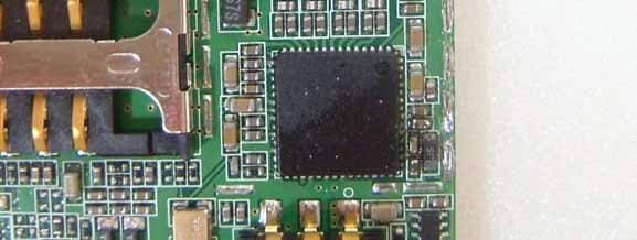
FCC ID: NPQI170 Copyright Ⓒ 2007, DIGITAL EMC Co., Ltd. View 1 FCC ID: NPQI170 Copyright Ⓒ 2007, DIGITAL EMC Co., Ltd. View 2 FCC ID: NPQI170 Copyright Ⓒ 2007, DIGITAL EMC Co., Ltd. View 3 FCC ID: NPQI170 Copyright Ⓒ 2007, DIGITAL EMC Co., Ltd. View 4 FCC ID: NPQI170 Copyright Ⓒ 2007, DIGITAL EMC Co., Ltd. View 5 (GSM Antenna) FCC ID: NPQI170 Copyright Ⓒ 2007, DIGITAL EMC Co., Ltd. View 6(Bluetooth antenna) FCC ID: NPQI170 Copyright Ⓒ 2007, DIGITAL EMC Co., Ltd. View 7 FCC ID: NPQI170 Copyright Ⓒ 2007, DIGITAL EMC Co., Ltd. View 8
Parts List/Tune Up Info
Applicant: Telian Corp. FCC ID : NPQI170 TUNE-UP PROCEDURE There are no user accessible adjustments or tuning in this GSM phone. All necessary adjustments and tuning are performed during manufacture of the product. Any adjustments or tuning after service or repair are done as part of that process as special equipment is required to perform such adjustments.
RF Exposure Info
1 PRODUCT SPECIFICATION SEKWANGProvider SKA703-0000AAPart No. MGQ3180 (I170)Model Name TELIANCustomer INTENNAProduct Name No.: SEKWANG 2007-4 Date : 2007. 4. 09 ApprovedChecked CheckedSubmitted SEKWANG 2 -Table of Contents - 1. Product History ---------------------------------------------3 2. Electrical Feature -------------------------------------------- 4 2.1 Frequency Band 2.2 Impedance 2.3 Matching circuit 2.4 VSWR 2.5 Directive ness 2.6 Maximum Power 3. Environment Test --------------------------------------------6 3.1 Operating Temperature Test 3.2 Temperature Cycling Test 3.3 Corrosion Resistance test 4. Electric Performance Data ------------------------------------- 8 4.1 Smith-Chart & VSWR 4.2 3D Gain Data 3 1. Product History 19 17 18 20 21 22 25 24 23 16 15 14 13 12 11 10 9 8 7 6 5 4 3 2 임시승인원 07.04.09 1 RemarkChangesDataNo. 4 2. Electrical Feature 2.1 Frequency Band 2.2 Impedance 2.2.1 Input Impedance - R =50Ω 2.2.2 Measuring Method By using Network Analyzer, connect the antenna installed handset to the reflection point of Analyzer and measure the impedance value within the designated frequency band. 2.3 Matching circuit Matching Circuit is composed in free space of 2.1 frequency band while satisfying customer’s requirements. Figure 2.3.1 Matching circuit 1710MHz ~ 1785MHz Rx 1710MHz ~ 1785MHz Tx DCS1800 1805MHz ~ 1880MHz Rx 1710MHz ~ 1785MHz Tx GSM900 1930MHz ~ 1990MHz 1850MHz ~ 1910MHz 869MHz ~ 894MHz 824MHz ~ 849MHz RxTxRxTx FREQUENCY PCSGSM850BAND 5 2.4 VSWR Impedance Matching optimization is performed under the below mentioned environment. 2.4.1. Free Space Environment 2.4.2 Measuring Method Connect (soldering) 50Ω semi-rigid coaxial cable to the 50Ω spot in handset. To minimize the loss of transmission, semi-rigid coaxial cable is used. Including PCB, the handset shouldn’t be different from the one, which will be used for mass production. Specification should be the same for all frequency bands. Free Space means that Handset is put on the surface of no conducting plastic. 2.5 Directive ness Omni-directional (Horizontal) 2.6 Maximum Power - P=2W under - 894MHz 5.5:1 824MHz GSM850 1990MHz1850MHz1880MHz1710MHz960MHz880MHz -5.0:1 DCS1800 4.5:1-3.5:1- VSWR PCSGSM900 BAND -0.79 dBi -5.25 dBi DCS1800 GAIN -5.62 dBi-4.84 dBi-6.65 dBiAvg. -1.50 dBi-1.82 dBi-3.00 dBiPeak GSM900PCSGSM850BAND 6 3. Environment Test 3.1 Operating Temperature Test 3.1.1 Test Condition Temperature = -30°C, +80°C Duration time = 1 hour 3.1.2 Requirements After the test, the antenna must not have an outer damage, and also it must pass requirement shown in 2.4. 3.1.3 Measuring Method Antenna is kept at -30°C for 1 hour and +80°C for 1 hour and than passed test of 2.4 3.2 Temperature Cycling Test 3.2.1 Test Condition -Low cycling Temperature TLC = -40°C - High cycling Temperature THC = +80°C - 1Cycle = 4 hours - Test number = 10Cycle 3.2.2 Requirements After the test, the antenna must not have an outer damage, and also it must pass requirement shown in 2.4. 3.2.3 Measuring Method Antenna is kept at low temperature -40°C for 2 hours and increase the temperature up to +80°C within 2 hour and kept for another 2 hours at the same temperature will be 1 cycle. As shown in Figure 3.2.1 repeat 10 cycle and kept for 2 hour in normal temperature. 7 Figure 3.2.1 Temperature Cycling +20°C t2 t1 Time/Hours 2Hr2Hr2Hr Temp./°C 2Hr 3.3 Corrosion Resistance Test 3.3.1 Test Condition -NaCl = 90% - Water Temperature = 60°C - Duration Time = 96 hours 3.3.2 Requirements After the test, the antenna must not have an outer damage, and also it must pass requirement shown in 2.4. 3.3.3 Measuring Method Antenna is soaked in sodium chloride solution at temperature +60°C and 90%(NaCl) for 96 hours and dry out. 8 4. Electric Performance Data 4.1 Smith-Chart & VSWR GSM900,DCS1800_CLOSE 9 4.2 3D Gain Data GSM850_GSM900 10 DCS1800_PCS1900
RF Exposure Info
DEMC#DR50110705W Copyright ○ c 2007, DIGITAL EMC Co., Ltd. Page 1 of 24 683-3, Yubang-Dong, Yongin-Si, Kyunggi-Do, Korea. 449-080 Tel: +82-31-321-2664 Fax: +82-31-321-1664 http://www.digitalemc.com SAR TEST REPORT Dates of Tests: May 25~28, 2007 Test Report S/N:DR50110705W Test Site : DIGITAL EMC CO., LTD. FCC ID APPLICANT FCC Classification: Licensed Portable Transmitter Held to Ear (PCE) EUT Type: GSM850/PCS1900 Dual Band GPRS Terminal with Bluetooth Equipment Model Name i170 Add Name MGQ3180C Brand Name Very Kool Test Device Serial No.: Identical prototype TX Frequency Range: 824.20 ~848.80 MHz (GSM850) 1850.20 ~ 1909.80 MHz (PCS1900) RX Frequency Range: 869.2 ~893.8 MHz (GSM850) 1930.2 ~ 1989.8 MHz (PCS1900) Max. RF Output Power: 0.456 W ERP GSM850 (26.59dBm) 0.981 W EIRP PCS1900 (29.92dBm) Max. SAR Measurement: 0.558 mW/g GSM850 Head SAR // 0.515 mW/g GSM850 GPRS Body SAR 0.839 mW/g PCS1900 Head SAR // 0.833 mW/g PCS1900 GPRS Body SAR Application Type: Certification Rule Part(s): §2.1093; FCC/OET Bulletin Supplement C[July 2001] Data of issue: May 30, 2007 Tested by : Reviewed by : Sun-Kyu Ryu (Engineer) Harvey Sung (Chief Engineering Director) This wireless portable device has been shown to be capable of compliance for localized specific absorption rate (SAR) for uncontrolled environment/general population exposure limits specified in ANSI/IEEE Std. C95.1-1992 and had been tested in accordance with the measurement procedures specified in FCC/OET Bulletin 65 Supplement C (2001) and IEEE Std. 1528-2003. I attest to the accuracy of data. All measurements reported herein were performed by me or were made under my supervision and are correct to the best of my knowledge and belief. I assume full responsibility for the completeness of these measurements and vouch for the qualifications of all persons taking them. NPQI170 Telian Corporation DEMC#DR50110705W Copyright ○ c 2007, DIGITAL EMC Co., Ltd. Page 2 of 24 1. INTRODUCTION ...................................................................................................... 3 SAR DEFINITION .................................................................................................... 3 2. SAR MEASUREMENT SETUP......................................................................................... 4 Robotic System.......................................................................................................... 4 System Hardware ....................................................................................................... 4 System Electronics...................................................................................................... 4 3. DASY4 E-FIELD PROBE SYSTEM................................................................................... 5 Probe Measurement System......................................................................................... 5 Probe Specifications .................................................................................................... 5 4. Probe Calibration Process............................................................................................ 6 Dosimetric Assessment Procedure.................................................................................. 6 Free Space Assessment ............................................................................................... 6 Temperature Assessment ............................................................................................ 6 5. PHANTOM & EQUIVALENT TISSUES.............................................................................. 7 SAM Phantom ........................................................................................................... 7 Brain & Muscle Simulating Mixture Characterization ....................................................... 7 Device Holder for Transmitters..................................................................................... 7 6. TEST SYSTEM SPECIFICATIONS.................................................................................. 8 Automated Test System Specifications.......................................................................... 8 7. DOSIMETRIC ASSESSMENT & PHANTOM SPECS ........................................................... 9 Measurement Procedure............................................................................................. 9 Specific Anthropomorphic Mannequin (SAM) Specifications.............................................. 9 8. DEFINITION OF REFERENCE POINTS .......................................................................... 10 EAR Reference Point................................................................................................... 10 Handset Reference Points............................................................................................ 10 9. TEST CONFIGURATION POSITIONS ............................................................................. 11 Positioning for Cheek/Touch ........................................................................................ 11 Positioning for Ear /15° Tilt ......................................................................................... 12 Body Holster /Belt Clip Configurations .......................................................................... 13 10. ICNIRP GUIDELINES RF EXPOSURE LIMITS.................................................................. 14 Uncontrolled Environment ........................................................................................... 14 Controlled Environment............................................................................................... 14 11. MEASUREMENT UNCERTAINTIES............................................................................... 15 SAR Measurement Uncertainties .................................................................................. 15 12. SYSTEM VERIFICATION.............................................................…
Text truncated - open the document above for the full version.
RF Exposure Info
Copyright ○ c 2007, DIGITAL EMC Co., Ltd. DIPOLE CALIBRATION Copyright ○ c 2007, DIGITAL EMC Co., Ltd. 1. 835 Dipole Calibration Copyright ○ c 2007, DIGITAL EMC Co., Ltd. 2. 1900 Dipole Calibration
RF Exposure Info
Copyright ○ c 2007, DIGITAL EMC Co., Ltd. PROBE CALIBRATION
RF Exposure Info
DIGITAL EMC CO., LTD DUT: Dipole 835 MHz; Type: D835V2; Serial: D835V2 - SN:464 Communication System: CW; Frequency: 835 MHz;Duty Cycle: 1:1 Medium parameters used: f = 835 MHz; σ = 0.887 mho/m; ε r = 41.1; ρ = 1000 kg/m 3 Phantom section: Flat Section DASY4 Configuration: Probe: ET3DV6 - SN1703; ConvF(6.52, 6.52, 6.52); Calibrated: 2006-09-20; Electronics: DAE3 Sn519 Phantom: SAM with 835MHz; Type: SAM; Serial: TP-1223 Measurement SW: DASY4, V4.6 Build 23; Postprocessing SW: SEMCAD, V1.8 Build 161 Test Date: 2007-05-28; Ambient Temp: 21.0; Tissue Temp: 20.5 Dipole Validation Area Scan (51x101x1): Measurement grid: dx=15mm, dy=15mm Zoom Scan (7x7x7)/Cube 0: Measurement grid: dx=5mm, dy=5mm, dz=5mm Power Drift = -0.001 dB Peak SAR (extrapolated) = 3.62 W/kg SAR(1 g) = 2.44 mW/g; SAR(10 g) = 1.6 mW/g 0 dB = 2.64mW/g DIGITAL EMC CO., LTD DUT: Dipole 1900 MHz; Type: D1900V2; Serial: D1900V2 - SN:5d029 Communication System: CW; Frequency: 1900 MHz;Duty Cycle: 1:1 Medium parameters used: f = 1900 MHz; σ = 1.45 mho/m; ε r = 40; ρ = 1000 kg/m 3 Phantom section: Flat Section DASY4 Configuration: Probe: ET3DV6 - SN1703; ConvF(5.38, 5.38, 5.38); Calibrated: 2006-09-20; Electronics: DAE3 Sn519 Phantom: SAM 1800/1900 MHz; Type: SAM; Serial: TP-1224 Measurement SW: DASY4, V4.6 Build 23; Postprocessing SW: SEMCAD, V1.8 Build 161 Test Date: 2007-05-25; Ambient Temp: 21.0; Tissue Temp: 20.5 Dipole Validation Area Scan (51x81x1): Measurement grid: dx=15mm, dy=15mm Zoom Scan (7x7x7)/Cube 0: Measurement grid: dx=5mm, dy=5mm, dz=5mm Power Drift = 0.025 dB Peak SAR (extrapolated) = 17.9 W/kg SAR(1 g) = 10.2 mW/g; SAR(10 g) = 5.34 mW/g 0 dB = 11.5mW/g DIGITAL EMC CO., LTD DUT: i170; Type: Bar Type Communication System: GSM 850; Frequency: 824.2 MHz;Duty Cycle: 1:8.3 Medium parameters used: f = 824.2 MHz; σ = 0.877 mho/m; ε r = 41.2; ρ = 1000 kg/m 3 Phantom section: Right Section DASY4 Configuration: Probe: ET3DV6 - SN1703; ConvF(6.52, 6.52, 6.52); Calibrated: 2006-09-20; Electronics: DAE3 Sn519 Phantom: SAM with 835MHz; Type: SAM; Serial: TP-1223 Measurement SW: DASY4, V4.6 Build 23; Postprocessing SW: SEMCAD, V1.8 Build 161 Date: 2007-05-28; Ambient Temp: 21.0; Tissue Temp:20.5 Right Touch GSM Ch.128, Ant Intenna, Standard Battery Area Scan (61x91x1): Measurement grid: dx=15mm, dy=15mm Zoom Scan (5x5x7)/Cube 0: Measurement grid: dx=8mm, dy=8mm, dz=5mm Power Drift = -0.007 dB Peak SAR (extrapolated) = 0.718 W/kg SAR(1 g) = 0.558 mW/g; SAR(10 g) = 0.397 mW/g 0 dB = 0.590mW/g DIGITAL EMC CO., LTD DUT: i170; Type: Bar Type Communication System: GSM 850; Frequency: 836.6 MHz;Duty Cycle: 1:8.3 Medium parameters used: f = 836.6 MHz; σ = 0.887 mho/m; ε r = 41; ρ = 1000 kg/m 3 Phantom section: Right Section DASY4 Configuration: Probe: ET3DV6 - SN1703; ConvF(6.52, 6.52, 6.52); Calibrated: 2006-09-20; Electronics: DAE3 Sn519 Phantom: SAM with 835MHz; Type: SAM; Serial: TP-1223 Measurement SW: DASY4, V4.6 Build 23; Postprocessing SW: SEMCAD, V1.8 Build 161 Date: 2007-05-28; Ambient Temp: 21.0; Tissue Temp:20.5 Right Touch GSM Ch.190, Ant Intenna, Standard Battery Area Scan (61x91x1): Measurement grid: dx=15mm, dy=15mm Zoom Scan (5x5x7)/Cube 0: Measurement grid: dx=8mm, dy=8mm, dz=5mm Power Drift = 0.027 dB Peak SAR (extrapolated) = 0.688 W/kg SAR(1 g) = 0.529 mW/g; SAR(10 g) = 0.375 mW/g 0 dB = 0.558mW/g DIGITAL EMC CO., LTD DUT: i170; Type: Bar Type Communication System: GSM 850; Frequency: 848.8 MHz;Duty Cycle: 1:8.3 Medium parameters used: f = 848.8 MHz; σ = 0.896 mho/m; ε r = 40.9; ρ = 1000 kg/m 3 Phantom section: Right Section DASY4 Configuration: Probe: ET3DV6 - SN1703; ConvF(6.52, 6.52, 6.52); Calibrated: 2006-09-20; Electronics: DAE3 Sn519 Phantom: SAM with 835MHz; Type: SAM; Serial: TP-1223 Measurement SW: DASY4, V4.6 Build 23; Postprocessing SW: SEMCAD, V1.8 Build 161 Date: 2007-05-28; Ambient Temp: 21.0; Tissue Temp:20.5 Right Touch GSM Ch.251, Ant Intenna, Standard Battery Area Scan (61x91x1): Measurement grid: dx=15mm, dy=15mm Zoom Scan (5x5x7)/Cube 0: Measurement grid: dx=8mm, dy=8mm, dz=5mm Power Drift = 0.029 dB Peak SAR (extrapolated) = 0.721 W/kg SAR(1 g) = 0.547 mW/g; SAR(10 g) = 0.385 mW/g 0 dB = 0.574mW/g DIGITAL EMC CO., LTD DUT: i170; Type: Bar Type Communication System: GSM 850; Frequency: 836.6 MHz;Duty Cycle: 1:8.3 Medium parameters used: f = 836.6 MHz; σ = 0.887 mho/m; ε r = 41; ρ = 1000 kg/m 3 Phantom section: Right Section DASY4 Configuration: Probe: ET3DV6 - SN1703; ConvF(6.52, 6.52, 6.52); Calibrated: 2006-09-20; Electronics: DAE3 Sn519 Phantom: SAM with 835MHz; Type: SAM; Serial: TP-1223 Measurement SW: DASY4, V4.6 Build 23; Postprocessing SW: SEMCAD, V1.8 Build 161 Date: 2007-05-28; Ambient Temp: 21.0; Tissue Temp:20.5 Right Tilt GSM Ch.190, Ant Intenna, Standard Battery Area Scan (61x91x1): Measurement grid: dx=15mm, dy=15mm Zoom Scan (5x5x7)/Cube 0: Measurement grid: dx=8mm, dy=8mm, dz=5mm Power Drift = -0.003 dB Peak SAR (extrapolated) = 0.815 W/kg SAR(1 g) = 0.320 mW/g; SAR(10 g) = 0.197 mW/g 0 dB = 0.330mW/g DIGITAL EMC CO., LTD DUT: i170; Type: Bar Type Communication System: GSM 850; Frequency: 824.2 MHz;Duty Cycle: 1:8.3 Medium parameters used: f = 824.2 MHz; σ = 0.877 mho/m; ε r = 41.2; ρ = 1000 kg/m 3 Phantom section: Left Section DASY4 Configuration: Probe: ET3DV6 - SN1703; ConvF(6.52, 6.52, 6.52); Calibrated: 2006-09-20; Electronics: DAE3 Sn519 Phantom: SAM with 835MHz; Type: SAM; Serial: TP-1223 Measurement SW: DASY4, V4.6 Build 23; Postprocessing SW: SEMCAD, V1.8 Build 161 Date: 2007-05-28; Ambient Temp: 21.0; Tissue Temp:20.5 Left Touch GSM Ch.128, Ant Intenna, Standard Battery Area Scan (61x91x1): Measurement grid: dx=15mm, dy=15mm Zoom Scan (5x5x7)/Cube 0: Measurement grid: dx=8mm, dy=8mm, dz=5mm Power Drift = -0.275 dB Peak SAR (extrapolated) = 0.729 W/kg SAR(1 g) = 0.557 mW/g; SAR(10 g) = 0.391 mW/g 0 dB = 0.596mW/g DIGITAL EMC CO., LTD DUT: i170; Type: Bar Type Communication System: GSM 850; Frequency: 836.6 MHz;Duty Cycle: 1:8.3 Medium parameters used: f = 836.6 MHz; σ…
Text truncated - open the document above for the full version.
Test Report
DEMC#DR50110705A Copyright ○ c 2007, DIGITAL EMC Co., Ltd. Page 1 of 48 683-3, Yubang-Dong, Yongin-Si, Kyunggi-Do, Korea. 449-080 Tel: +82-31-321-2664 Fax: +82-31-321-1664 http://www.digitalemc.com CERTIFICATE OF COMPLIANCE FCC Part 22 & 24 Certification Dates of Tests: April 23 ~ 30, 2007 Test Report S/N:DR50110705A Test Site : DIGITAL EMC CO., LTD. FCC ID. APPLICANT Classification : Licensed Portable Transmitter Held to Ear (PCE) FCC Rule Part(s) : §22(H), §24(E), §2 EUT Type : GSM850 / PCS1900 Dual Band GPRS Terminal with Bluetooth Equipment Model name : i170 Add model name : MGQ3180C Brand name : Very Kool Serial number : Identical prototype TX Frequency Range : 824.2 ~ 848.8 MHz (GSM850) / 1850.2 ~ 1909.8 MHz (PCS1900) RX Frequency Range : 869.2 ~ 893.8 MHz (GSM850) / 1930.2 ~ 1989.8 MHz (PCS1900) Max. RF Output Power : 0.456 W ERP GSM850 : 0.981 W EIRP PCS1900 Max. SAR Measurement : 0.558 mW/g GSM850 Head SAR // 0.515 mW/g GSM850 GPRS Body SAR : 0.839 mW/g PCS1900 Head SAR // 0.833 mW/g PCS1900 GPRS Body SAR Date of Issue : May 7, 2007 NPQI170 Telian Corporation DEMC#DR50110705A Copyright ○ c 2007, DIGITAL EMC Co., Ltd. Page 2 of 48 TABLE OF CONTENTS ATTACHMENT CONFIDENTIALITY LETTER ATTACHMENT AUTHOLIZATION LETTER ATTACHMENT TEST REPORT 1 SCOPE 3 2 INTRODUCTION 4 3 TEST REPORT 5 3.1 SUMMARY OF TEST 5 3.2 POWER OUTPUT 6 3.3 OCUPIED BANDWIDTH 13 3.4 OCCUPIED BANDWIDTH EMISSION LIMIT 17 3.5 SPURIOUS EMISSION AT ANT. TERMINAL 23 3.6 FIELD STRENGTH OF SPURIOUS RADIATION 33 3.7 FREQUENCY STABILITY 40 4 TEST EQUIPMENT 45 5 EMISSION DESIGNATOR 47 6 CONCLUSION 48 ATTACHMENT : PART LOCATION ATTACHMENT : FCC ID LABEL & LOCATION ATTACHMENT : TEST SETUP PHOTOGRAPHS ATTACHMENT : EXTERNAL PHOTOGRAPHS ATTACHMENT : INTERNAL PHOTOGRAPHS ATTACHMENT : BLOCK DIAGRAM(S) ATTACHMENT : SCHEMATIC DIAGRAM(S) ATTACHMENT : OPERATIONAL DESCRIPTION ATTACHMENT : PARTS LI S T ATTACHMENT : USER’S MANUAL ATTACHMENT : SAR TEST REPORT ATTACHMENT : SAR VALIDATION PLOTS ATTACHMENT : SAR TEST PLOTS ATTACHMENT : SAR TEST SETUP PHOTOGRAPHS ATTACHMENT : PROBE CALIBRATION ATTACHMENT : DIPOLE CALIBRATION DEMC#DR50110705A Copyright ○ c 2007, DIGITAL EMC Co., Ltd. Page 3 of 48 MEASUREMENT REPORT 1. Scope Measurement and determination of electromagnetic emissions (EME) of radio frequency devices including intentional and/or unintentional radiators for compliance with the technical rules and regulations of the Federal Communications Commission. §2.1033 General Information z FCC ID: z Quantity: z Tx Freq. Range: z Rx Freq. Range: z Max. Power Rating: z FCC Classification(s): z Equipment (EUT) Type: z Modulation(s): z Frequency Tolerance: z FCC Rule Part(s): z Dates of Tests: z Place of Tests: z Test Report S/N: NPQI170 The pre-product 824.2 ~ 848.8 MHz (GSM850) / 1850.2 ~ 1909.8 MHz (PCS1900) 869.2 ~ 893.8 MHz (GSM850) / 1930.2 ~ 1989.8 MHz (PCS1900) 0.456W ERP GSM850 0.981W EIRP PCS1900 Licensed Portable Transmitter Held to Ear (PCE) GSM850 / PCS1900 Dual Band Terminal Equipment GMSK ± 0.00025 % (2.5ppm) §22(H), §24(E), §2 April 23 ~ 30, 2007 DIGITAL EMC DR50110705A Applicant: Telian Corporation Address: 5 th FL. Namjeun Bldg, 53-3 Haan-Dong, Kwangmyung-Si, Kyunggi-Do, Korea Attention: Wayne Hwang (Senior Manager) DEMC#DR50110705A Copyright ○ c 2007, DIGITAL EMC Co., Ltd. Page 4 of 48 2. General Information This report contains the result of tests performed by: DIGITAL EMC CO., LTD. Address : 683-3, Yubang-Dong, Yongin-Si, Kyunggi-Do, Korea. 449-080 http://www.digitalemc.com E-mail : [email protected] Tel: +82-31-321-2664…
Text truncated - open the document above for the full version.
Contact Information
Applicant
Wayne Hwang(CTO)
Test Firm
DT&C Co.,Changho Lee
Technical Specifications
| # | Rule Parts | Frequency Range | Power Output | Emission | Tolerance |
|---|---|---|---|---|---|
| 2 | 24E | 1.85 GHz - 1.91 GHz | 981.00 mW | 253KGXW | 2.5 ppm |
Other Applications from Telian Corporation
NPQK1000
Jan 24, 2008GSM850/PCS1900 Dual Band GPRS Terminal Equip. w/BT
Equipment Class
PCE - PCS Licensed Transmitter held to ear
NPQI405
Aug 06, 2007GSM850 / PCS1900 Dual Band GPRS Terminal with BT
Equipment Class
DSS - Part 15 Spread Spectrum Transmitter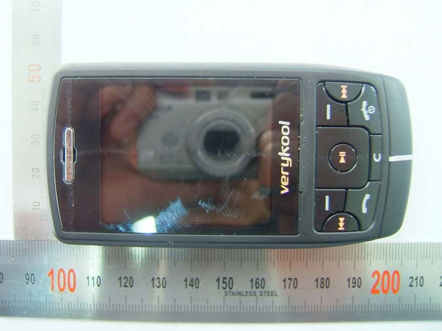
NPQMGQ9180
Mar 13, 2007Quad-Band GSM/GPRS Handset with Bluetooth
Equipment Class
DSS - Part 15 Spread Spectrum Transmitter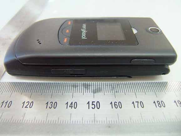
NPQMGQ7180
Feb 27, 2007Quad-Band GSM/GPRS Handset with Bluetooth
Equipment Class
PCE - PCS Licensed Transmitter held to ear
NPQFGD6280
Sep 27, 2006GSM850/PCS1900 Dual Band WLL Terminal
Equipment Class
PCB - PCS Licensed Transmitter