NTTR810CELLULAR REPEATER
WJ Communications, Inc.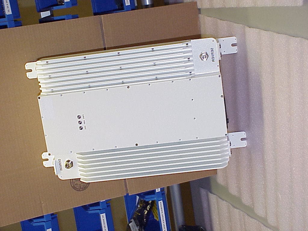
Click to zoom
Application Details
- Equipment Class
- TNB - Licensed Non-Broadcast Station Transmitter
- Date of Grant
- Mar 05, 2000
- Application Purpose
- Original Equipment
- Date of Application
- Nov 23, 1999
- Equipment Note
- CELLULAR REPEATER
- Frequency Range
- 869.00000000 - 894.00000000
- Company
- WJ Communications, Inc.
- Country
- United States
Documents & Files
Document Text
Text extracted from the exhibit documents filed with the FCC. Open a document above to read the original.
Users Manual
W Watkins-Johnson Company Repeater Manual WATKINS-JOHNSON COMPANY 3333 Hillview Avenue Palo Alto, CA 94304-1223 Watkins-Johnson Company PCS Repeater Manual “This drawing, print, or document and subject matter disclosed herein are proprietary items to which Watkins-Johnson Company retains the exclusive right of dissemination, reproduction, manufacture and sale. This drawing, print or document is submitted in confidence for consideration by the designated recipient or intended using organization alone unless permission for further disclosure is expressly granted in writing.” 09/99 WATKINS-JOHNSON COMPANY 3333 Hillview Avenue Palo Alto, CA 94304-1223 (800) 951-4401 Internet: http://www.wj.com RepeaterTable of Contents i Table of Contents SectionTopicPage Chapter 1General Information and Safety Precautions1-1 Introduction1-1 Specifications1-6 Safety Considerations1-10 Description1-10 Mechanical1-11 Environmental Conditions1-12 Chapter 2Installation2-1 Introduction2-1 Unpacking and Inspection2-1 Preparation For Use2-1 Pre-Installation Information2-2 Installation Information2-3 Repeater Initial Turn-On Procedure2-6 Setup2-6 Isolation and Alignment Procedure2-7 Multicarrier & FCC Spurious2-9 Connectors2-10 Storage2-11 Packing for Reshipment or Storage2-11 Chapter 3Operation3-1 Introduction3-1 Operating Instructions3-1 Chapter 4Scheduled Maintenance4-1 Introduction4-1 Scheduled Maintenance Action Index4-1 Equipment Required4-1 Preventive Maintenance Procedures4-1 General Maintenance4-2 Alignment4-2 Repair4-2 Chapter 5Drawings5-1 R1910 Mounting5-1 R1920 Mounting Plate5-2 R1920 and BB42 Mounting5-3 R1920 Electrical and System Configuration5-4 RepeaterGeneral Information and Safety Precautions 1-1 CHAPTER 1 GENERAL INFORMATION AND SAFETY PRECAUTIONS 1-1INTRODUCTION This manual provides information pertaining to the installation, operation, and maintenance of the Watkins-Johnson Repeaters, shown in Figure 1-1. The model number represents the type of repeater. This manual covers the following types of repeaters. The model numbers and letters are defined in the following example. Example: R1910CAD-1M is a PCS indoor repeater, with CDMA modulation, using frequency bands A and D, 1.25mhz bandwidth, with a modem. Repeater Model NumberRepeater Description R1910PCS Inbuilding Repeater R1920PCS High Power Repeater R1930PCS Medium Power Repeater R1940PCS Low Power Repeater R810Cellular Inbuilding Repeater R820Cellular High Power Repeater ModulationPCS Frequency Band BandwidthInterface Option CDMA = C TDMA = T GSM = G AD* BE* FC* -1 = 1.25 MHz -2 = 0.20 MHz -3 = 5.00 MHz -4 = 15.0 MHz -5 = 1.00 MHz -6 = 4.50 MHz -7 = 7.00 MHz M= modem * Specifies dual bands. ** The R810 and R820 cover the entire A or B band RepeaterGeneral Information and Safety Precautions 1-2 This manual is divided into five chapters, the first four covering a particular topic for the operation and maintenance of the unit. Chapter 5 includes drawings to assist in mounting WJ repeaters. The topics are as follows: ChapterTopic 1General Information and Safety Precautions 2Installation 3Operation 4Scheduled Maintenance 5Drawings RepeaterGeneral Information and Safety Precautions 1-3 Figure 1-1. R1910 and R810 Repeater RepeaterGeneral Information and Safety Precautions 1-4 Figure 1-2. R1920/30/40, R820 Repeater RepeaterGeneral Information and Safety Precautions 1-5 Chapter 1 provides a general description of the Repeater and summarizes the electrical, mechanical, and environmental characteristics. It also provides a tabular listing of the Repeater performance specifications. Safety precautions to be observed while operating or servicing the unit are also explained. Chapter 2 provides instructions for the initial inspection and installation of the Repeater. It describes the purpose and function of all I/O connectors, provides initial start-up instructions, and provides installation verification tests. Chapter 3 describes the purpose and function of all remote controls and status indicators and explains how to operate the unit. Chapter 4 provides a scheduled maintenance action index and describes maintenance procedures that should be performed on a regular basis, such as cleaning and inspection. Chapter 5 provides drawings useful when mounting a WJ repeater to a structure. RepeaterGeneral Information and Safety Precautions 1-6 1-2SPECIFICATIONS Table 1-1. R1910 Specification DESCRIPTIONSPECIFICATION FrequencyBand AD, BE, or FC Output Power100 mWatts CDMA 500 mWatts TDMA 500 mWatts PCS-1900 (GSM) Filter Bandwidth1.25 MHz CDMA (other filters available) 200KHz TDMA (other filters available) 200 kHz GSM-1900 (other filters available) Noise Figure4 dB Typical Maximum Input without damage-10 dBm Input Impedance50 ohms Gain Range40 dB to 70 dB or 65 dB to 95 dB Gain Steps2 dB Signal Delay5 usec max Power115 / 230 VAC, 60 / 50 Hz, 1.6 / 0.8 Amps Alarms & StatusSynthesizer, Amplifiers, Power Amplifier, Output Power, Oscillation InterfaceRS-232 (modem optional) ControlGain, Channel frequency, Auto Level Control, and Tracking Offset CoolingConvection TemperatureOperating:-10 to +45ºC Storage:-40 to +85ºC Size12” x 16” x 3” Weight19 lbs. Weather ResistanceNEMA 12 Connectors RF Control AC Power Type N 9 pin Dsub Female NEMA Type 5-ISP RepeaterGeneral Information and Safety Precautions 1-7 Table 1-2. R1920 Specification DESCRIPTIONSPECIFICATION FrequencyBand AD, BE, or FC Output Power8 Watts CDMA 10 Watts TDMA 15 Watts GSM-1900 Filter Bandwidth1.25 MHz CDMA (other filters available) 200 kHz TDMA (other filters available) 200 kHz GSM-1900 (other filters available) Noise Figure4 dB Typical Maximum Input without damage-10 dBm Input Impedance50 ohms Gain Range65 dB to 95 dB Gain Steps2 dB Signal Delay5 usec max Power115 / 230 VAC, 60 / 50 Hz, 4 / 2 Amps Alarms & StatusSynthesizer, Amplifiers, Power Amplifier, Output Power, Oscillation InterfaceRS-232 and modem ControlGain, Channel frequency, Auto Level Control, and Tracking Offset CoolingConvection TemperatureOpera…
Text truncated - open the document above for the full version.
Cover Letter(s)
WATKINS - JOHNSON COMPANY 3333 Hillview Ave Stanford Research Park Palo Alto, California 94304-1223 (650) 493-4141 FAX: (650) 813-2447 October 26, 1999 FCC Laboratory 7435 Oakland Mills Road Columbia, MD 21046 Re: Request for Confidentiality Applicant: Watkins-Johnson Company FCC ID: NTTR810 To whom it may concern, We request that certain parts of the type acceptance application for the referenced device be kept confidential and be withheld from public review. This request is made under the provisions of 0.459 et seq of the Rules. Here are portions of this application for which confidentiality are requested: Circuit block diagram Circuit schematics Rationale for request for confidentiality. Watkins-Johnson Company has invested time and materials in research and development to product the referenced product. Disclosure of the confidential portions of this application to competitors would give them competitive advantage in developing similar products. The $130 fee for confidentiality has been submitted along with the fee for type acceptance. If you have questions or need further information, please contact the undersigned. Sincerely, James A. Mravca Director of Cell Extender Products
ID Label/Location Info
PROPOSED FCC ID LABEL FORMAT AND LOCATION APPLICANT: WATKINS JOHNSON CO. MODEL NO: R-810 FCC ID: NTTR810 WATKINS JOHNSON CO. MODEL NO: R-810 FCC ID:NTTR810 This device complies with part 15 of the FCC Rules. Operation is subject to the following two conditions: (1) This device may not cause harmful interference, and (2) this device must accept any interference received, including interference that may cause undesired operation. FCC ID LABEL AREA
Operational Description
Watkins-Johnson R810 Repeater Description The WJR 810Repeaters are used to enhance the coverage of a PCS basestation. For example, inside buildings that do not allow sufficient signal strength from the basestation, service holes may exist in the coverage for wireless service. The WJ R810 is designed to solve that problem. Likewise, tall buildings in a metropolitan area, or mountains in a more rural area, can reduce basestation signal strength such that pockets of unusable areas develop. The WJ R810 is designed to solve that problem. The repeater receives the basestation signal from the Forward path through a diplexer. The signal is amplified by a Low Noise Amplifier (LNA) and then mixed down to an IF frequency. A local oscillator (LO) is generated by a VCO, synthesizer chip and 10MHz oscillator. The LO is used by both mixers. At the IF frequency of 70MHz the signal is amplified, attenuated and filtered by a SAW filter. The signal is then uncoverted back to the original frequency. The signal is filtered by a ceramic band pass filter to help eliminate the LO and then amplified. The amplified signal is passed through another diplexer to ensure that this signal does not affect the reverse path. The entire schemed is repeated for the reverse path that amplifies the handset signal. In the normal configuration, the repeater is connected to antennas. One antenna is pointed at the basestation and the other is used to retransmit the basestation signal inside the building. Outside BuildingInside Building Lightning Arrestor Figure 1-3. WJ R810 Typical Usage Repeater Server Antenna Donor Antenna WJ R810
Test Report
FCC CFR47 PART 22 SUBPART H CERTIFICATION TEST REPORT FOR CELLULAR REPEATER MODEL: R-810 FCC ID:NTTR810 REPORT NUMBER: 99U0531 ISSUE DATE:SEPT. 08, 1999 Prepared for WATKINS JOHNSON COMPANY 3333 Hillview Ave. Palo Alto, CA 94304 Prepared by COMPLIANCE CERTIFICATION SERVICES, INC. 1366 BORDEAUX DRIVE SUNNYVALE, CA 94089, USA TEL: (408) 752-8166 FAX: (408) 752-8168 REPORT NO: 99U531 DATE:09/08/1999 FCC ID: NTTR810 EUT: CELLULAR REPEATER 0 COMPLIANCE CERTIFICATION SERVICES DOCUMENT NO:CCSUP4031A 1366 BORDEAUX DRIVE SUNNYVALE, CA 94089 USA TEL:(408) 752-8166 FAX:(408) 752-8168 This report shall not be reproduced except in full, without the written approval of CCS. TABLE OF CONTENTS PAGE 1. FCC CERTIFICATION INFORMATION....................................................................................................1 2. TEST FACILITY..............................................................................................................................................4 3. ACCREDITATION AND LISTING...............................................................................................................4 4. MEASUREMENT INSTRUMENTATION....................................................................................................4 5. MEASURING INSTRUMENT CALIBRATION...........................................................................................4 6. UNITS OF MEASUREMENT.........................................................................................................................4 7. FCC 15.207 & 15.209.................................................................................................................................5 8. TEST EQUIPMENT LIST...............................................................................................................................6 9. EUT SETUP PHOTOS.....................................................................................................................................7 10. EXTERNAL I/O CABLE CONSTRUCTION DESCRIPTION..............................................................8 11. CONFIGURATION BLOCK DIAGRAM.................................................................................................9 12. PART 2: CERTIFICATION TEST REQUIREMENT:...........................................................................9 SECTION 2.1046: RF POWER OUTPUT..............................................................................................................9 SECTION 2.1047: MODULATION CHARACTERISTICS.................................................................................10 SECTION 2.1049: OCCUPIED BANDWIDTH...................................................................................................10 SECTION 2.1051: SPURIOUS EMISSION AT ANTENNA TERMINALS........................................................10 SECTION 2.1053: FIELD STRENGTH OF SPURIOUS RADIATION..............................................................11 SECTION 2.1055: FREQUENCY STABILITY...................................................................................................14 CHART OF PLOTS:..............................................................................................................................................16 REPORT NO: 99U0531 DATE: 09/08/1999 FCC ID: NTTR810 EUT: CELLULAR REPEATER 1 COMPLIANCE CERTIFICATION SERVICES DOCUMENT NO:CCSUP4031A 1366 BORDEAUX DRIVE SUNNYVALE, CA 94089 USA TEL:(408) 752-8166 FAX:(408) 752-8168 This report shall not be reproduced except in full, without the written approval of CCS. 1. FCC CERTIFICATION INFORMATION The following information is in accordance with FCC Rules, 47CFR Part2, Subpart J, Sections 2.1033 – 2.1055. 2.1033(c)(1) Applicant: WATKINS JOHNSON COMPANY 3333 Hillview Ave. Palo Alto, CA 94304 Contact person: Randall Riley Telephone number: (650) 813-2721 2.1033(c)(2) FCC ID: NTTR810 2.1033(c)(3) Instructions/Installation Manual Refer to Attachment: User’s Manual. 2.1033(c)(4) Type of emissions DXW (TDMA), F9W (CDMA), F8W(AMPS) 2.1033(c)(5) Frequency Range 824-849MHz(REV), 869-894MHz(FWD) 2.1033(c)(6) Range of Operation Power 0.0000001- 0.1Watts 2.1033(c)(7) Maximum Power Rating 0.100 WATTS Section 22.913(a); Maximum ERP. The effective radiated power (ERP) of base transmitters and cellular repeaters must not exceed 500 Watts. 2.1033(c)(8) Applied voltage and currents into the final transistor elements 4.8VDC at 1.2AMPS on Q409 and Q415 (0.100Watts) 2.1033(c)(9) Tune-up/Optimizations Procedure Refer to installation manual REPORT NO: 99U0531 DATE: 09/08/1999 FCC ID: NTTR810 EUT: CELLULAR REPEATER 2 COMPLIANCE CERTIFICATION SERVICES DOCUMENT NO:CCSUP4031A 1366 BORDEAUX DRIVE SUNNYVALE, CA 94089 USA TEL:(408) 752-8166 FAX:(408) 752-8168 This report shall not be reproduced except in full, without the written approval of CCS. 2.1033(c)(10) Complete Circuit Diagrams and Functional Diagram Refer to Schematics and Block Diagram . Confidentiality is requested for these items. 2.1033(c)(10a) Means for Frequency Stabilization Not Applicable. Eut is a repeater. 2.1033(c)(10b) Means for Suppressing of Spurious radiation. SAW filter. See Repeater description. 2.1033(c)(10c) Means for Limiting Modulation. Not Applicable. Eut is a repeater. 2.1033(c)(10d) Means for Limiting Power. Software control 2.1033(c)(11) Equipment Identification A drawing of the equipment identification nameplate appears in file titled: PROPOSED FCC ID LABEL FORMAT. 2.1033(c)(12) Photographs Photographs of the equipment, internal and external views, are found in the Attachment: Eut Photographs. 2.1033(c)(13) Description of Digital Modulation Techniques N/A EUT is repeater. 2.1033(c)(14) Standard Test Condition The power amplifier was tested under the following conditions. AC Supply Voltage: 120Vac, 60Hz The amplifier was aligned and tuned up according to manufacturer’s alignment procedure, prior to testing. All data presented represents the worst case parameter being measured.…
Text truncated - open the document above for the full version.
Contact Information
Applicant
Tim Buchner(Strategic Marketing)
Technical Contact
COMPLIANCE ENGINEERING SERVICES, INC.MIKE KUO
[email protected]408-752-8166
1366 BORDEAUX DRIVE · SUNNYVALE, California · United States
Non-Technical Contact
COMPLIANCE ENGINEERING SERVICES, INC.MIKE KUO
[email protected]408-752-8166
Test Firm
Compliance Certification ServicesRuss Lowell
Technical Specifications
| # | Rule Parts | Frequency Range | Power Output | Emission | Tolerance |
|---|---|---|---|---|---|
| 3 | 22.901(d) | 869 MHz - 894 MHz | 89.00 mW | F8W | 2.5 ppm |
Other Applications from WJ Communications, Inc.
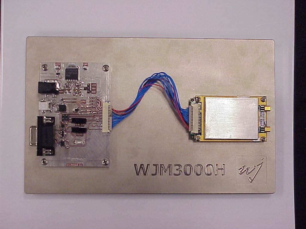
NTTWJM3000
Jan 11, 2007RFID Reader Module
Equipment Class
DSS - Part 15 Spread Spectrum Transmitter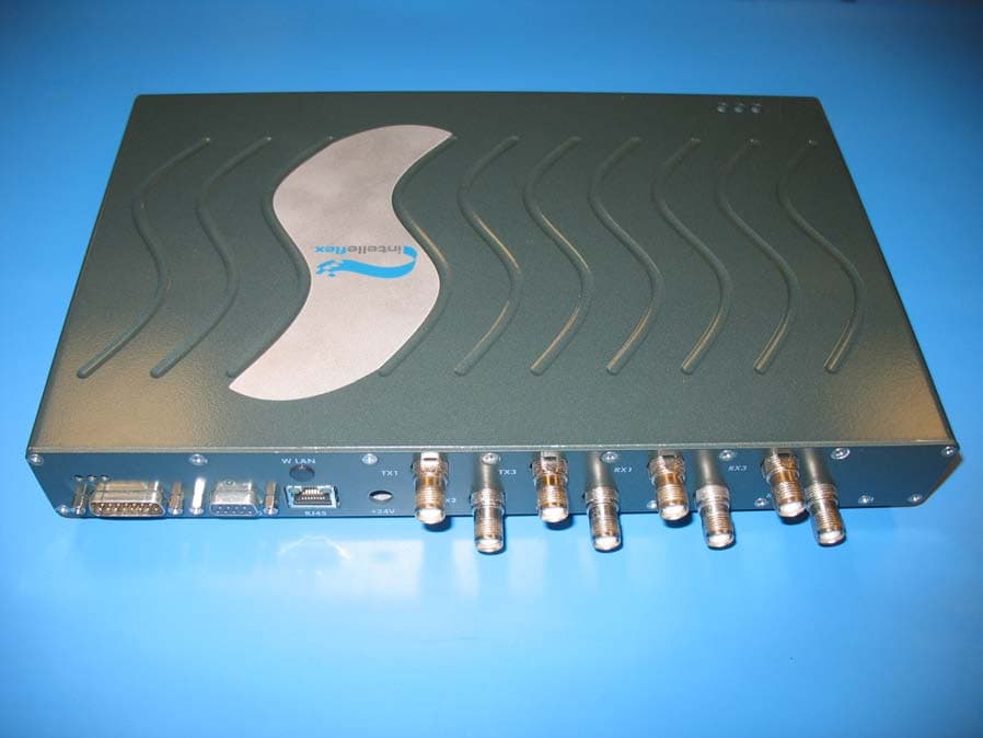
NTTSR320
Jun 20, 2006RFID Tag Reader
Equipment Class
DSS - Part 15 Spread Spectrum Transmitter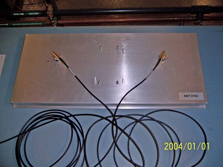
NTTWJSR22XX
Sep 12, 2005902-928MHz RFID Reader
Equipment Class
DSS - Part 15 Spread Spectrum Transmitter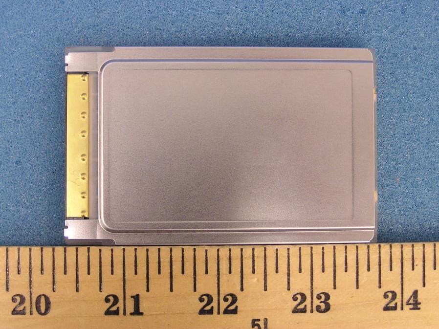
NTTWJMPR7XXX
Dec 12, 2004RFID Reader
Equipment Class
DSS - Part 15 Spread Spectrum Transmitter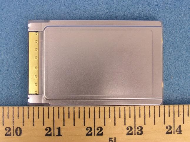
NTTWJMPR6XXX
Dec 09, 2004RFID Reader
Equipment Class
DSS - Part 15 Spread Spectrum Transmitter