NTTWJMPR6XXXRFID Reader
WJ Communications, Inc.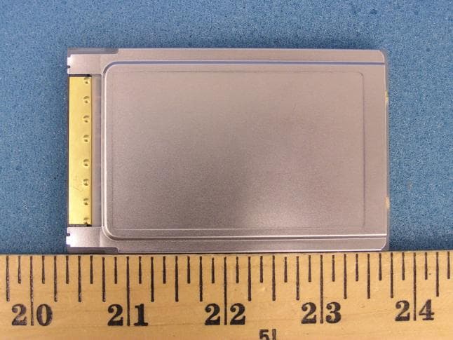
Click to zoom
Application Details
- Equipment Class
- DSS - Part 15 Spread Spectrum Transmitter
- Date of Grant
- Dec 09, 2004
- Application Purpose
- Original Equipment
- Date of Application
- Dec 09, 2004
- Equipment Note
- RFID Reader
- Frequency Range
- 903.00000000 - 927.00000000
- Company
- WJ Communications, Inc.
- Country
- United States
Documents & Files
Document Text
Text extracted from the exhibit documents filed with the FCC. Open a document above to read the original.
Users Manual
MPR series User’s Manual: Draftversion 0.95 11/4/04page 1 1 MPR Series MultiProtocol RFID Reader User’s Manual Version 0.95 11/4/04 1.1 Cover sheet MPR series User’s Manual: Draftversion 0.95 11/4/04page 2 1.2 TOC MPR series User’s Manual: Draftversion 0.95 11/4/04page 3 1.3 Introduction 1.3.1 Contents of this Document This manual describes installation and operation of the WJ Communications MPR5000, MPR6000, and MPR7000 PC-card-compatible UHF RFID readers. A description of the installation and use of the demonstration Graphical User Interface is also provided. The Application Programmer’s Interface to the MPR-series devices is described. 1.3.2 Audience This manual assumes that the reader is generally familiar with Windows personal computers and, if applicable, Windows CE or PocketPC handheld devices. An introduction to RFID technology is provided for readers who are new to the field. 1.3.3 RFID System Quickstart Radio Frequency Identification (RFID) uses electromagnetic waves to exchange information between a tag, containing (at least) a number uniquely identifying that physical tag and by implication the object to which it is attached, and a reader. RFID tags are analogous to bar codes, but can contain more information and are more versatile. The WJ Communications MPR-series readers are UHF readers, operating at a frequency of roughly 902- 928 MHz. These readers are compatible with EPCglobal Class 0 and EPCglobal Class 1 RFID tags, as well as class 0+ tags. They are not compatible with HF (13.56 MHz) tags generally used in Smart Cards, or LF (125/134 KHz) tags generally used in animal identification. MPR-series readers are configured as PC-card (PCMCIA)-slot-compatible modules, and require a host such as a laptop computer or handheld computer. With an appropriate host and if necessary an external antenna, an MPR-series reader can be used to acquire the unique identification number (UID) of one or more compatible tags in its reading range. When multiple tags are present in the field, collision resolution algorithms are applied to allow effectively simultaneous reading of all the readable tags. A more detailed discussion of RFID technology can be found in section 1.5. MPR series User’s Manual: Draftversion 0.95 11/4/04page 4 1.3.4 Product Description 1.3.4.1 MPR 5000 card with integral antenna The MPR5000 includes an antenna attached to the reader module, and is ready to be used as received. The antenna is not removable or replaceable. 1.3.4.2 MPR6000/7000 card with external antenna ports The MPR6000 and 7000 incorporate two MMCX-type adaptors for connecting up to two external antennas. The ports are interchangeable, and only one antenna may be used at any given time if desired. 1.3.4.2.1 Approved Antennas The MPR6000 and 7000 are approved for operation with either of two external antennas: a nearly-isotropic low-gain monopole antenna for general short-range use, and a higher-gain directional antenna when a specified coverage region is desired. MPR series User’s Manual: Draftversion 0.95 11/4/04page 5 Use of other than the approved antennas with this unit may result in harmful interference with other users, and cause the unit to fail to meet regulatory requirements. Professional installation is required for the MPR6000 and MPR7000 models. 1.3.4.2.1.1 Low gain, isotropic For general-purpose use where convenience is the main consideration, substantially isotropic operation is desired, and read range is unimportant, the MPR6000/7000 may be connected to a Maxrad Z1789 The Z1789 is shipped with an MMCX connector and may be attached directly to the card antenna ports, or a small-diameter extension cable, such as an RG-405 cable, may be used. Small-diameter cables that are mechanically appropriate for connection to an MMCX adaptor are generally relatively lossy and should not be used for lengths exceeding 2 meters (6 feet). 1.3.4.2.1.2 High gain, directional For applications where read range and control of the read zone are important, the MPR6000 may be connected to a Maxrad model MP9026CPRXFPT. This antenna is a right-hand-circularly polarized panel antenna, with a gain of 8.5 dBiC, front-to-back ratio of approximately 17 dB, and a 3 dB beamwidth of approximately 80°. The MPR7000 may be connected to a Maxrad model MP9027XFPTMSMA. This antenna is a right-hand- circularly polarized panel antenna, with a gain of 5.2 dBiC, front-to-back ratio of approximately 17 dB, and a 3 dB beamwidth of approximately 80°. The antenna is available with an N-female connector (-NF), or a male SMA connector (-MSMA). In either case, an adaptor may be required to connect the antenna to the MPR antenna port. Note that caution should be exercised in attaching any long, relatively heavy cables to the MPR MMCX adaptors, as these adaptors are not intended to tolerate large mechanical stresses. WJ Communications recommends that the MPR output port be connected through a short length of small-diameter cabling, such as RG-405, with stress relief to protect the card adaptor in the event of displacement of the cabling, and then an adaptor should be used to mate this intermediate cable to the antenna cabling. 1.3.4.3 CD with this manual, drivers, and demo software 1.4 Installation and Operation with demonstration Graphical User Interface 1.4.1 Introduction This chapter describes how to install the the WJ MPR series Multi-Protocol RFID PC Card Demo Software for Microsoft Windows, Windows CE, and PocketPC operating systems. These instructions are written for Microsoft XP operating system. For other MS Windows operating systems the details of some instructions may be slightly different, but by following the onscreen instructions the installation will proceed similarly. Windows 95 and Windows NT operating systems are not currently supported. The PC and Pocket PC demos were written using the .NET Framework and Compact Framework respectively. Thus, the MS .NET Common Runtime must be installed for these programs (and their installers)…
Text truncated - open the document above for the full version.
Cover Letter(s)
tel: 650-726-1263 fax: 650-726-1252 [email protected] Thomas N. CokeniasEMC &Radio Approvals Test & Consulting Services for Commercial, Military, International Compliance P.O. Box 1086 El Granada, CA 94018 Compliance Certification Services4 December 2004 561 F Monterey Road Morgan Hill CA 95037 Attention: Mike Kuo Reviewing Engineer Applicant: WJ Communications Inc. FCC ID: (a) NTTWJMPR5XXX (b) NTTWJMPR6XXX (c) NTTWJMPR7XXX Dear Mike, Request is hereby submitted, per section 0.459 of the Rules, on behalf of my client WJ Communications Inc., to withhold from public review certain portions of the application for equipment certification for the referenced FCC identifier. In particular, the following sections of the application and report are requested to be kept confidential: Block Diagrams Schematic Operational Description Rationale for request for confidentiality: WJ has invested considerable time and materials in research and development to produce the referenced product. Disclosure of the confidential portions of this application to competitors would give them competitive advantage in developing similar products. If you have questions or need further information, please contact the undersigned. Sincerely, THOMAS N. COKENIAS EMC Consultant/Agent for WJ Communications Inc.
External Photos
WJ Communications Inc. FCC ID: NTTWJMPR6XXX 0.5 Watt RFID Reader External Photographs
ID Label/Location Info
WJ RFI D Reader FCC ID Labels FCC ID: NTTWJMPR5XXX IC: 3374A-MPR5XXX This device complies with Part 15 of the FCC Rules. Operation is subject to the following two conditions: (1) this device may not cause harmful interference, and (2) this device must accept any interference received, including interference that may cause undesired operation. FCC ID: NTTWJMPR6XXX IC: 3374A-MPR6XXX This device complies with Part 15 of the FCC Rules. Operation is subject to the following two conditions: (1) this device may not cause harmful interference, and (2) this device must accept any interference received, including interference that may cause undesired operation. FCC ID: NTTWJMPR7XXX IC: 3374A-MPR7XXX This device complies with Part 15 of the FCC Rules. Operation is subject to the following two conditions: (1) this device may not cause harmful interference, and (2) this device must accept any interference received, including interference that may cause undesired operation
ID Label/Location Info
FCC ID: NTTWJMPR5XXX Label Location Area FCC IDs: NTTWJMPR6XXX, NTTWJMPR7XXX
Parts List/Tune Up Info
Portable Duck Antenna Z1789 SMR Portable Antenna This portable antenna is designed to cover SMR frequen- cies from 902 to 960 MHz with a VSWR of less than 2:1 across the band. Its rugged, flexible design makes it suitable for use in a wide variety of applications. Features and Benefits: •Ground plane independent, half-wave coaxial dipole design. Provides improved antenna performance and installation flexibility. •Flexible design. Added durability that allows use in demanding wireless environments. General Specifications: SMR Portable Antenna Polarization: Linear, vertical Nominal Impedance: 50 Ohms Mechanical Specifications Electrical Specifications Model #Frequency RangeWave Length VSWR at ResonanceMaximum PowerGain Z1789902-960 MHz1/2 wave<2:150 Watts2.1 dBi Model #Connector TypeDesignAntenna HeightTemperature Range Z1789SMA PlugCoaxial dipole8.30” (211 mm)-30°C to +60°C
Parts List/Tune Up Info
39 XtremeWave™ XF Series General Specifications: Directional panel antennas Radome Material: UL 94-V0 plastic Polarization: Linear, vertical/horizontal (all models but MP9026CPLXFPT and MP9026CPRXFPT) Left hand circular (MP9026CPLXFPT only) Right hand circular (MP9026CPRXFPT only) Nominal Impedance: 50 Ohms Mounting Method: The XtremeWave™ directional panel antennas are designed to cover 800/900 MHz frequencies with a VSWR of less than 1.5:1, obtaining maximum gain with an attractive, low-profile package. All models provide efficient and stable perfor- mance across the band and can be mounted indoors or outdoors. Features and Benefits: •Highly efficient antenna element provides high performance in an attractive, compact housing. •UL94-V0 plastic and PC board. Provides UL’s highest flame retardant rating allowing maximum placement flexibility. Meets the most stringent building fire rating codes. •Attractive, low profile housing. Blends well with indoor and outdoor environments where aesthetic considerations are important. •Corner exit, high performance RG-58/U pigtail design. Permits the linear polarized panel to be mounted in vertical or horizontal polarity with a wide variety of connectors. •Optional UL 910 rated Plenum cable. Allows the cable to be installed in the strictest indoor mounting locations, including air ducts. •Optional adjustable mounting brackets for indoor and outdoor mounting. Provide maximum flexibility for indoor or outdoor installations. 800/900 MHz Directional Panel Antenna Series Model/MountMPAB7MPAB8MPAB11MPAB12 All modelsoptionaloptionaloptionaloptional Mount Description Heavy duty outdoor adjustable mount with +/-35° uptilt/downtilt. Same as MPAB8 but bracket is longer. Heavy duty outdoor adjustable mount with 17° uptilt/downtilt. Short adjustable indoor mount. Long adjustable indoor wall corner mount. The XtremeWave™ directional panels feature a UV resistant, UL94-V0 plastic housing that meets UL’s highest flame retardant rating for maximum placement flexibility. These panels meet stringent building fire rating codes for in-building installations, and can also be safely installed outdoors. Product shown with optional MPAB12 long adjustable indoor wall corner mount (above) and optional MPAB8 heavy duty adjustable outdoor mast mount. Model # Frequency RangeGain Front-to- Back Ratio 3 dB Horizontal Beamwidth 3 dB Vertical BeamwidthVSWR Maximum Power Input Connector Options MP8066XFPT806-960 MHz8.1 dBi> 17 dB70°60°< 1.5:120 Watts N female (part #NF) standard. Other options are available. MP8906XFPT890-960 MHz8.6 dBi> 17 dB70°60°< 1.5:120 Watts MP9027XFPT902-928 MHz9.1 dBi> 17 dB65°65°< 1.5:120 Watts MP9026CPLXFPT902-928 MHz8.5 dBic> 20 dB65°65°< 1.5:120 Watts MP9026CPRXFPT902-928 MHz8.5 dBic> 20 dB65°65°< 1.5:120 Watts Model # Wind Loading (Frontal) @100 mph Wind Temperature RangeDimensionsWeightHigh Performance Cable MP8066XFPT27.9 lbs.-40°C to +70°C 8.8” x 8.1” x 1.6” (22.4 x 20.6 x 4.06 cm) 1.2 lbs (0.54 kg) 12” (30.5 cm) RG58/U* MP8906XFPT27.9 lbs.-40°C to +70°C 8.8” x 8.1” x 1.6” (22.4 x 20.6 x 4.06 cm) 1.2 lbs (0.54 kg) 12” (30.5 cm) RG58/U* MP9027XFPT27.9 lbs.-40°C to +70°C 8.8” x 8.1” x 1.6” (22.4 x 20.6 x 4.06 cm) 1.2 lbs (0.54 kg) 12” (30.5 cm) RG58/U* MP9026CPLXFPT27.9 lbs.-40°C to +70°C 8.8” x 8.1” x 1.6” (22.4 x 20.6 x 4.06 cm) 1.2 lbs (0.54 kg) 12” (30.5 cm) RG58/U* MP9026CPRXFPT27.9 lbs.-40°C to +70°C 8.8” x 8.1” x 1.6” (22.4 x 20.6 x 4.06 cm) 1.2 lbs (0.54 kg) 12” (30.5 cm) RG58/U* * UL910 rated cable optional. ORDER (800) 323-9122 FAX (630) 372-8077 www.pctel.com Mechanical Specifications Electrical Specifications Specifications 40
RF Exposure Info
WJ Communications FCCIDs: NTTWJMPR6XXX, NTTWJMPR7XXX RF Hazard Distance Calculation mW/cm2 from Table1:0.60 Max RF PowerTX AntennaMPEMPE, inchesComment P, dBmG, dBiSafe Distance, cm 29.86.022.58.8-MPR7XXX 26.89.022.48.8-MPR6XXX Basis of Calculations: E^2/3770 = S, mW/cm2 E, V/m = (Pwatts*Ggain*30)^.5/d, meters d = ((Pwatts*G*30)/3770*S))^0.5 For mobile or fixed location transmitters, minimum separation is 20 cm, even if calculations yield lower numbers
Test Report
FCC CFR47 PART 15 SUBPART C CERTIFICATION TEST REPORT FOR PCMCIA RFID READER CARD MODEL NUMBER: MPR6000 FCC ID: NTTWJMPR6XXX REPORT NUMBER: 04U2954-3 ISSUE DATE: NOVEMBER 22, 2004 Prepared for WJ COMUNICATIONS 401 RIVER OAKS PARKWAY SAN JOSE, CA 95134 Prepared by COMPLIANCE CERTIFICATION SERVICES 561F MONTEREY ROAD, MORGAN HILL, CA 95037, USA TEL: (408) 463-0885 FAX: (408) 463-0888 REPORT NO: 04U2954-3 DATE: NOVEMBER 22, 2004 EUT: HALF WATT PCMCIA RFID READER CARD: MPR6000 FCC ID: NTTWJMPR6XXX Page 2 of 93 COMPLIANCE CERTIFICATION SERVICES DOCUMENT NO: CCSUP4031A 561F MONTEREY ROAD, MORGAN HILL, CA 95037 USA TEL: (408) 463-0885 FAX: (408) 463-0888 This report shall not be reproduced except in full, without the written approval of CCS. Revision History Rev. Revisions Revised By REPORT NO: 04U2954-3 DATE: NOVEMBER 22, 2004 EUT: HALF WATT PCMCIA RFID READER CARD: MPR6000 FCC ID: NTTWJMPR6XXX Page 3 of 93 COMPLIANCE CERTIFICATION SERVICES DOCUMENT NO: CCSUP4031A 561F MONTEREY ROAD, MORGAN HILL, CA 95037 USA TEL: (408) 463-0885 FAX: (408) 463-0888 This report shall not be reproduced except in full, without the written approval of CCS. TABLE OF CONTENTS 1. ATTESTATION OF TEST RESULTS............................................................................................. 5 2. TEST METHODOLOGY.................................................................................................................. 6 3. FACILITIES AND ACCREDITATION.......................................................................................... 6 4. CALIBRATION AND UNCERTAINTY.......................................................................................... 6 4.1. MEASURING INSTRUMENT CALIBRATION............................................................................. 6 4.2. MEASUREMENT UNCERTAINTY............................................................................................... 6 5. EQUIPMENT UNDER TEST............................................................................................................7 5.1. DESCRIPTION OF EUT..............................................................................................................7 5.2. MAXIMUM OUTPUT POWER.................................................................................................... 7 5.3. DESCRIPTION OF AVAILABLE ANTENNAS............................................................................. 7 5.4. SOFTWARE AND FIRMWARE.................................................................................................... 7 5.5. WORST-CASE CONFIGURATION AND MODE......................................................................... 8 5.6. DESCRIPTION OF TEST SETUP................................................................................................ 9 6. TEST AND MEASUREMENT EQUIPMENT.............................................................................. 11 7. LIMITS AND RESULTS................................................................................................................. 12 7.1. ANTENNA PORT CHANNEL TESTS FOR CLASS 0 MODUALTION....................................... 12 7.1.1. 20 dB BANDWIDTH......................................................................................................... 12 7.1.2. HOPPING FREQUENCY SEPARATION......................................................................... 16 7.1.3. NUMBER OF HOPPING CHANNELS............................................................................. 18 7.1.4. AVERAGE TIME OF OCCUPANCY............................................................................... 20 7.1.5. PEAK OUTPUT POWER.................................................................................................. 24 7.1.6. MAXIMUM PERMISSIBLE EXPOSURE........................................................................ 28 7.1.7. CONDUCTED SPURIOUS EMISSIONS.......................................................................... 31 7.2. ANTENNA PORT CHANNEL TESTS FOR CLASS 1 MODULATION..................................... 40 7.2.1. 20 dB BANDWIDTH......................................................................................................... 40 7.2.2. HOPPING FREQUENCY SEPARATION......................................................................... 44 7.2.3. NUMBER OF HOPPING CHANNELS............................................................................. 46 7.2.4. AVERAGE TIME OF OCCUPANCY............................................................................... 48 7.2.5. PEAK OUTPUT POWER.................................................................................................. 52 7.2.6. MAXIMUM PERMISSIBLE EXPOSURE........................................................................ 56 7.2.7. CONDUCTED SPURIOUS EMISSIONS.......................................................................... 59 7.3. RADIATED EMISSIONS.............................................................................................................68 7.3.1. TRANSMITTER RADIATED SPURIOUS EMISSIONS................................................. 68 7.3.2. TRANSMITTER RADIATED EMISSIONS ABOVE 1 GHZ WITH 3 dBi MONOPOLE ANTENNA AND CLASS 0 MODULATION ................................................................................... 71 REPORT NO: 04U2954-3 DATE: NOVEMBER 22, 2004 EUT: HALF WATT PCMCIA RFID READER CARD: MPR6000 FCC ID: NTTWJMPR6XXX Page 4 of 93 COMPLIANCE CERTIFICATION SERVICES DOCUMENT NO: CCSUP4031A 561F MONTEREY ROAD, MORGAN HILL, CA 95037 USA TEL: (408) 463-0885 FAX: (408) 463-0888 This report shall not be reproduced except in full, without the written approval of CCS. 7.3.3. TRANSMITTER RADIATED EMISSIONS ABOVE 1 GHZ WITH 9.2dBi CIRCULARLY POLARIZED ANTENNA AND CLASS 0 MODULATION .................................. 72 7.3.4. TRANSMITTER RADIATED EMISSIONS ABOVE 1 GHZ WITH 3 dBi MONOPOLE ANTENNA AND CLASS 1 MODULATION ........................................................................…
Text truncated - open the document above for the full version.
Test Setup Photos
WJ CommunicationsTEST SETUP PHOTOSFCC ID:NTTWJMPR6XXX Antenna Conducted Radiated below 1 GHz, 9 dBi antenna WJ CommunicationsTEST SETUP PHOTOSFCC ID:NTTWJMPR6XXX Radiated above 1 GHz , omni antenna Radiated above 1 GHz, 9 dBi antenna Matrix RFID tag WJ CommunicationsTEST SETUP PHOTOSFCC ID:NTTWJMPR6XXX AC Line Conducted WJ CommunicationsTEST SETUP PHOTOSFCC ID:NTTWJMPR6XXX
Contact Information
Applicant
Tim Buchner(Strategic Marketing)
Test Firm
Compliance Certification Services IncSteve Cheng
Technical Specifications
| # | Rule Parts | Frequency Range | Power Output |
|---|---|---|---|
| 1 | 15C | 903 MHz - 927 MHz | 475.00 mW |
Other Applications from WJ Communications, Inc.
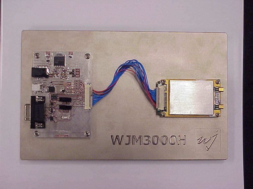
NTTWJM3000
Jan 11, 2007RFID Reader Module
Equipment Class
DSS - Part 15 Spread Spectrum Transmitter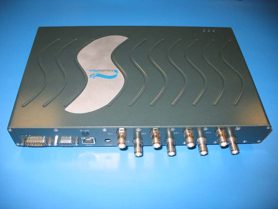
NTTSR320
Jun 20, 2006RFID Tag Reader
Equipment Class
DSS - Part 15 Spread Spectrum Transmitter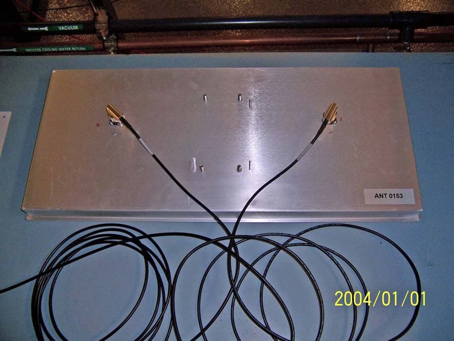
NTTWJSR22XX
Sep 12, 2005902-928MHz RFID Reader
Equipment Class
DSS - Part 15 Spread Spectrum Transmitter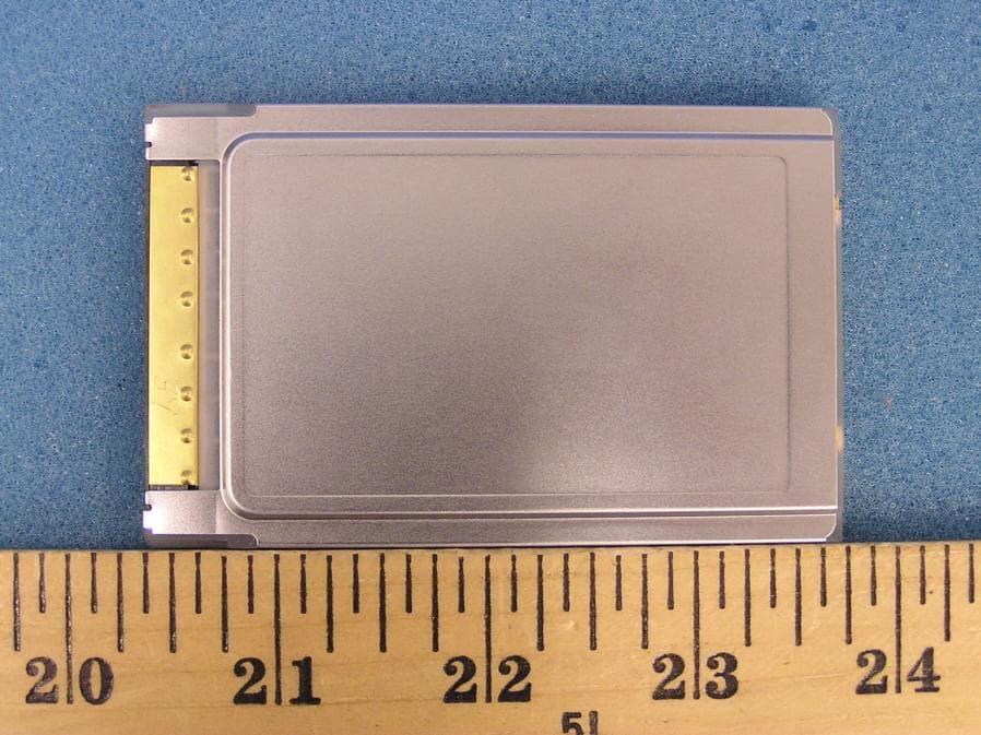
NTTWJMPR7XXX
Dec 12, 2004RFID Reader
Equipment Class
DSS - Part 15 Spread Spectrum Transmitter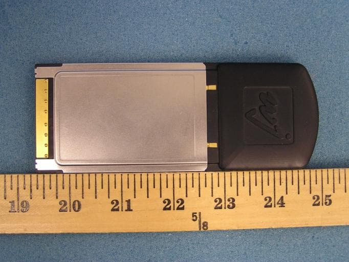
NTTWJMPR5XXX
Dec 09, 2004RFID Reader
Equipment Class
DSS - Part 15 Spread Spectrum Transmitter