NTTSR320RFID Tag Reader
WJ Communications, Inc.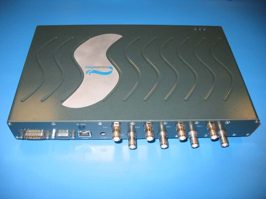
Click to zoom
Application Details
- Equipment Class
- DSS - Part 15 Spread Spectrum Transmitter
- Date of Grant
- Jun 20, 2006
- Application Purpose
- Original Equipment
- Date of Application
- Jun 20, 2006
- Equipment Note
- RFID Tag Reader
- Frequency Range
- 902.75000000 - 927.25000000
- Company
- WJ Communications, Inc.
- Country
- United States
Documents & Files
Document Text
Text extracted from the exhibit documents filed with the FCC. Open a document above to read the original.
Users Manual
RFID Fixed IBeam Reader User’s Manual Cover sheet Copyright© 2006 by Intelleflex Corp. Subject to change without notice. This information is provided “as is,” and Intelleflex makes no claims of fit for purposes intended, merchantability or other. All trademarks, service marks, trade names and logos are used in good faith and remain the property of their rightful owners. page 1 Table of Contents 1.1 Introduction......................................................................................................................................3 1.1.1 Contents of this Document.........................................................................................................3 1.1.2 Audience.....................................................................................................................................3 1.1.3 Product Description....................................................................................................................3 1.1.4 Unpacking and Inspection..........................................................................................................3 1.1.5 Product Installation.....................................................................................................................4 1.2 Installation and Operation of demonstration Graphical User Interface.....................................4 1.2.1 Minimum System Requirements................................................................................................4 1.2.2 Software Installation...................................................................................................................5 1.2.3 Starting the Apache server..........................................................................................................6 1.2.4 Reader Administrator Console (TagHunterTM).........................................................................6 1. Find Tags (Button).............................................................................................................................8 2. Air Protocol (Radio Button)...............................................................................................................8 3. Setting a Configuration (drop down list box).....................................................................................9 4. Antenna selection (checkboxes).........................................................................................................9 5. Tag Inventory (operation)...................................................................................................................9 6. Refresh (Button)................................................................................................................................. 9 1. Manage Tag Memory.......................................................................................................................11 2. Raw Memory Read Write.................................................................................................................12 3. EM_Data..........................................................................................................................................13 1. New config.......................................................................................................................................20 1.3 Host-Reader Interface....................................................................................................................22 1.4 Troubleshooting / technical support.............................................................................................22 1.5 Technical specifications..................................................................................................................22 1.6 Notices..............................................................................................................................................22 1.6.1 RFID limitations.......................................................................................................................22 1.6.2 Safety........................................................................................................................................22 1.6.3 Limitation of liability................................................................................................................23 1.6.4 Patents.......................................................................................................................................23 1.6.5 Copyright notice.......................................................................................................................23 1.6.6 Comments and feedback...........................................................................................................23 1.7 Regulatory Compliance..................................................................................................................23 1.7.1 FCC Statement..........................................................................................................................23 Copyright© 2006 by Intelleflex Corp. Subject to change without notice. This information is provided “as is,” and Intelleflex makes no claims of fit for purposes intended, merchantability or other. All trademarks, service marks, trade names and logos are used in good faith and remain the property of their rightful owners. page 2 1.1 Introduction 1.1.1 Contents of this Document This manual describes installation and operation of the Intelleflex Corporation’s UHF RFID Stationary IBeam Readers. A description of the installation and use of the demonstration Graphical User Interface is also provided. The Application Programmer’s Interface to the IBeam Reader using SLRPP protocol and communicating over the Ethernet port is described in a separate API document. 1.1.2 Audience This manual assumes that the reader is generally familiar with RFID technology and Windows personal computers. The primary audi…
Text truncated - open the document above for the full version.
Block Diagram
PAGE 1 OF 1 SR320 RFID Reader Theory of Operation The SR320 RFID reader consists of the Interface Board, Controller Board, and an RF Board as shown in Figure 1. RF BoardInterface BoardController Board PLL Control Power Control I & Q RF Power IF Gain Filter Select Antenna Select Modulation PA Enable +5V Serial I/F Reset BootMode GPIO1 GPIO2 Figure 1: SR320 RFID Reader Block Diagram A block diagram of the Interface Board is shown in Figure 2. The Interface Board contains an Arm9 microprocessor that provides the primary interfaces of the reader. Those interfaces include three light emitting diodes (LEDs), digital I/O in the form of 4 inputs and 4 outputs, 4 configuration switches, a reader RESET switch, an RS-232 compatible serial port, and a 10/100 Base-T Ethernet interface. Ethernet I/FI/O IF RESET Switch ARM9 Microprocessor Configuration Switches (4) Status LEDs (3)FLASH MemoryEEPROMRAM Memory Serial I/F Figure 2: Interface Board Block Diagram A host computer commands the Interface Board via the Ethernet interface using the EPC-Global Reader Protocol based on the June 26, 2005 draft release specification. The Controller Board is commanded by the Interface Board’s Arm9 to perform communication with RFID tags. The Controller Board consists of an Arm7 microcontroller and a digital signal processor (DSP). The Arm7 receives requests from the Interface board over a TTL serial port. The Arm7 then controls the RF Board to perform the RFID forward link modulation and reception of the RFID tag’s backscatter, which is decoded by the DSP and transmitted to the Arm7 over a SPI interface. A block diagram of the controller board is shown in Figure 3 below. PAGE 2 OF 2 10-bit ADCDSP 512Kx16 FLASH Microcontroller Clock DC Power JTAG SPIGPIO JTAG 50 MHz 20 MHz 5V DC 3.3V 1.8V 1.2V I Q Interface Board I/FRF Board I/F Figure 3: Controller Board Block Diagram The RF Board consists of a transmitter and receiver, both employing the same local oscillator and direct up- and down-conversion from the carrier frequency, configured for operation within the US Industrial Scientific and Medical (ISM) band at 902-928 MHz. A block diagram of the RF Board is shown below in Figure 4. The transmitter signal both provides power to passive tags and delivers commands to the tags. The system is thus full-duplex in the sense that the transmitter continues to operate during reception of tag signals, but half-duplex in terms of data transmission, since when tag data is being received the transmitted signal is unmodulated CW. In a typical exchange, the transmitter is first powered up and commanded to send a CW signal to provide power to tags in the read zone. Then a baseband on-off-keyed modulation, appropriately filtered, is imposed on the CW signal with a mixer. The reader data provides tags with synchronization information, requests tags to transmit their unique IDs and other data in memory, and may write new data to a tag or erase its memory, etc. After a command is given, the transmitter continues to transmit unmodulated CW power at the carrier frequency; this CW signal both provides power to operate the tag’s integrated circuit, and provides the RF signal that the tags backscatter to send their signals back to the reader. The details vary depending on the protocol being used. PAGE 3 OF 3 Filter Power Detector Circulator Filter TX Mux RX Mux PA Modulation Detected Power Power Control PLL PLL Control VCO FilterAMPAMPFilterAMP 90° AMPFilterAMPAMP I+ I- Q+ Q- DC Power 24V DC 18V 9V 5V Figure 4: RF Board Block Diagram The backscattered signal is filtered and then mixed to baseband using the same VCO signal employed by the transmitter; the SR320 reader is a homodyne radio. In-phase / quadrature (I/Q) demodulation is employed in order to ensure that the baseband signal can be received despite variations in the absolute phase of the reflected carrier. (Without this provision, depending on the exact separation of the tag and reader antenna, the cable lengths, and other factors that cannot be controlled, the reflected signal would at times be in quadrature with the signal from the VCO, so that the mixer would produce no baseband output.) The outputs of the two mixers are filtered and amplified and then demodulated to extract the reflected signal from the tags. After each command set the power shuts down while processing of the commands proceeds. The nominal channel spacing is 500 KHz, providing 50 channels (with guard bands) within the ISM band. In accordance with FCC regulations, the carrier frequency periodically ‘hops’ in a pseudo-random fashion over the ISM band to avoid persistent interference with other unlicensed users.
Cover Letter(s)
tel: 650-726-1263 fax: 650-726-1252 [email protected] Thomas N. Cokenias EMC &Radio Approvals Test & Consulting Services for Commercial, Military, International Compliance P.O. Box 1086 El Granada, CA 94018 Compliance Certification Services 19 June 2006 561 F Monterey Road Morgan Hill CA 95037 Attention: Mike Kuo Reviewing Engineer Applicant: WJ Communications Inc. FCC ID: NTTSR320 Dear Mike, Request is hereby submitted, per section 0.459 of the Rules, on behalf of my client WJ Communications Inc., to withhold from public review certain portions of the application for equipment certification for the referenced FCC identifier. In particular, the following sections of the application and report are requested to be kept confidential: Schematic Rationale for request for confidentiality: WJ has invested considerable time and materials in research and development to produce the referenced product. Disclosure of the confidential portions of this application to competitors would give them competitive advantage in developing similar products. If you have questions or need further information, please contact the undersigned. Sincerely, THOMAS N. COKENIAS Agent for WJ Communications Inc.
Cover Letter(s)
tel: 650-726-1263 fax: 650-726-1252 [email protected] Thomas N. Cokenias EMC &Radio Approvals Test & Consulting Services for Commercial, Military, International Compliance P.O. Box 1086 El Granada, CA 94018 Compliance Certification Services 19 June 2006 561 F Monterey Road Morgan Hill CA 95037 Attention: Chris Harvey Reviewing Engineer Applicant: WJ Communications Inc. Re: Further details of EUT operation FCC ID: NTTSR320 Dear Chris, Per our conversation earlier today: Each channel is used equally on average. The EUT has a homodyne receiver and has an input bandwidth consistent with the measured 20 dB emission bandwidth. The associated receiver hops in synchronization with the transmitter, as the RX circuitry uses the TX local oscillator. The EUT design complies with all pertinent requirements when presented with a lengthy data stream, as the data streams for which the unit was designed were for standard packet streams from industry standard passive tags. The EUT complies with the non- coordination requirement. The tag backscatter frequencies are 120 kH displaced from TX on class 1 gen 2 tags, and 120 kHz and 230 kHz for class 3 tags. If you have questions or need further information, please contact the undersigned. Sincerely, THOMAS N. COKENIAS Agent for WJ Communications Inc.
Cover Letter(s)
1 Chris Harvey From: Thomas Cokenias [[email protected]] Sent: Monday, June 19, 2006 10:37 PM To: [email protected]@ccsemc.com Subject: Re: WJ COMMUNICATIONS INC, FCC ID: NTTSR520, Assessment NO.: AN06T5871, Notice#1 Attachments: 18JunRep1.1.pdf; label location.doc; SR320 ID label.pdf; reply 19Jun email.doc 18JunRep1.1.pdf (2 MB) label location.doc (654 KB) SR320 ID label.pdf (42 KB) reply 19Jun email.doc (48 KB) Hi Chris, Answers follow questions. Thanks for your quick response and diligence. Also, I am attaching a corrected report, some of the information was there because of cut and paste errors. The last page of the report has the revision information. Hopefully you'll quickly see there were no substantive changes and will be able to recommend grant before you leave, please let me know either way. best regards Tom On Jun 19, 2006, at 1:32 PM, <[email protected]> <charvey- [email protected]> wrote: > Tom, I have reviewed the above referenced TCB application and find > that the following items need to be addressed before the review can be > completed: > > 1. Please provide Label and Label placement exhibits which are missing > from the filing. > ANS 1 documents attached > 2. Please provide the backscatter frequencies of the RF Tags for the 2 > modulations available. ANS2 Refer to attached letter > 3. There are several FCC requirements that are not yet declared as > being compliant in the application referenced above. Please provide > declarations of compliance with the following items needed for FCC > 15.247 FHSS compliance: ANS 3 refer to attached letter. > Is each channel used equally on average, based on the technical > description? > Does the associated system receiver have a compliant input > bandwidth, based on the measured 20 dB emission bandwidth? > Does the associated system receiver have the ability to hop in > synchronization with the transmitter, based on the technical > description? > Does the design of the frequency hopping system allow it to comply > with all pertinent requirements when presented with a lengthy data > stream? > Does the frequency hopping system comply with the non- coordination > requirement? > > Please note that I am being called out of town for a family emergency > and will not be back into the office until Thursday morning (June 22). > 2 > The items indicated above must be submitted before processing can > continue on the above referenced application. Failure to provide the > requested information within 30 days of the original e-mail date may > result in application dismissal and forfeiture of the filing fee. > Also, please note that partial responses increase processing time and > should not be submitted. Any questions about the content of this > correspondence should be directed to the e-mail address listed below > the name of the sender. > > Best regards, > > Chris Harvey > [email protected]
External Photos
WJ Communications FCC ID: NTTSR320 RFID Reader – External Photos
ID Label/Location Info
WJ Communications Inc. FCC ID: NTTSR320 IC: 3374A-SR320 FCC ID: NTTSR320 IC: 3374A-SR320 Model No.: SR320 902-928 MHz Band
ID Label/Location Info
WJ Communication FCC ID: NTTSR320 Label location ID label location
Internal Photos
WJ Communications FCC ID: NTTSR320 RFID Reader – Internal Photos
Operational Description
PAGE 1 OF 5 SR320 RFID Reader Theory of Operation The SR320 RFID reader consists of the Interface Board, Controller Board, and an RF Board as shown in Figure 1. RF BoardInterface BoardController Board PLL Control Power Control I & Q RF Power IF Gain Filter Select Antenna Select Modulation PA Enable +5V Serial I/F Reset BootMode GPIO1 GPIO2 Figure 1: SR320 RFID Reader Block Diagram A block diagram of the Interface Board is shown in Figure 2. The Interface Board contains an Arm9 microprocessor that provides the primary interfaces of the reader. Those interfaces include three light emitting diodes (LEDs), digital I/O in the form of 4 inputs and 4 outputs, 4 configuration switches, a reader RESET switch, an RS-232 compatible serial port, and a 10/100 Base-T Ethernet interface. Ethernet I/FI/O IF RESET Switch ARM9 Microprocessor Configuration Switches (4) Status LEDs (3)FLASH MemoryEEPROMRAM Memory Serial I/F Figure 2: Interface Board Block Diagram A host computer commands the Interface Board via the Ethernet interface using the EPC-Global Reader Protocol based on the June 26, 2005 draft release specification. The Controller Board is commanded by the Interface Board’s Arm9 to perform communication with RFID tags. The Controller Board consists of an Arm7 microcontroller and a digital signal processor (DSP). The Arm7 receives requests from the Interface board over a TTL serial port. The Arm7 then controls the RF Board to perform the RFID forward link modulation and reception of the RFID tag’s backscatter, which is decoded by the DSP and transmitted to the Arm7 over a SPI interface. A block diagram of the controller board is shown in Figure 3 below. PAGE 2 OF 5 10-bit ADCDSP 512Kx16 FLASH Microcontroller Clock DC Power JTAG SPIGPIO JTAG 50 MHz 20 MHz 5V DC 3.3V 1.8V 1.2V I Q Interface Board I/FRF Board I/F Figure 3: Controller Board Block Diagram The RF Board consists of a transmitter and receiver, both employing the same local oscillator and direct up- and down-conversion from the carrier frequency, configured for operation within the US Industrial Scientific and Medical (ISM) band at 902-928 MHz. A block diagram of the RF Board is shown below in Figure 4. The transmitter signal both provides power to passive tags and delivers commands to the tags. The system is thus full-duplex in the sense that the transmitter continues to operate during reception of tag signals, but half-duplex in terms of data transmission, since when tag data is being received the transmitted signal is unmodulated CW. In a typical exchange, the transmitter is first powered up and commanded to send a CW signal to provide power to tags in the read zone. Then a baseband on-off-keyed modulation, appropriately filtered, is imposed on the CW signal with a mixer. The reader data provides tags with synchronization information, requests tags to transmit their unique IDs and other data in memory, and may write new data to a tag or erase its memory, etc. After a command is given, the transmitter continues to transmit unmodulated CW power at the carrier frequency; this CW signal both provides power to operate the tag’s integrated circuit, and provides the RF signal that the tags backscatter to send their signals back to the reader. The details vary depending on the protocol being used. PAGE 3 OF 5 Filter Power Detector Circulator Filter TX Mux RX Mux PA Modulation Detected Power Power Control PLL PLL Control VCO FilterAMPAMPFilterAMP 90° AMPFilterAMPAMP I+ I- Q+ Q- DC Power 24V DC 18V 9V 5V Figure 4: RF Board Block Diagram The backscattered signal is filtered and then mixed to baseband using the same VCO signal employed by the transmitter; the SR320 reader is a homodyne radio. In-phase / quadrature (I/Q) demodulation is employed in order to ensure that the baseband signal can be received despite variations in the absolute phase of the reflected carrier. (Without this provision, depending on the exact separation of the tag and reader antenna, the cable lengths, and other factors that cannot be controlled, the reflected signal would at times be in quadrature with the signal from the VCO, so that the mixer would produce no baseband output.) The outputs of the two mixers are filtered and amplified and then demodulated to extract the reflected signal from the tags. After each command set the power shuts down while processing of the commands proceeds. The nominal channel spacing is 500 KHz, providing 50 channels (with guard bands) within the ISM band. In accordance with FCC regulations, the carrier frequency periodically ‘hops’ in a pseudo-random fashion over the ISM band to avoid persistent interference with other unlicensed users. PAGE 4 OF 5 Operating SR320 Test Software Using The Console. Index: 1. Settings And Set Up 2. RFTEST Menu 1. Settings and Set Up Note: Since the instructions are provided to demonstrate the device’s use during certification testing, only set up for MS Windows is provided – as used during certification testing. a) Connect RS232 cable to SR320 reader as well as computer. b) Open Windows HyperTerminal, or equivalent, and input the following settings: Bits per second: 57600 Data bits: 8 Parity: none Stop bits: 1 Flow Control: none c) Apply 24V power supply; boot up sequence should occur. Note: The recommended power supply is a CUI Inc power supply, model No: 3A-501DN24 d) Allow the boot up sequence to finish, and hit <enter> to activate console, when instructed. 2. RFTEST Menu a) Navigate to the working directory by typing: cd work/c3test b) To initiate the test menu (RFTEST), type the command: ./rftest The RFTEST menu should appear. c) To select a specific output RF power, at the Test Menu, choose option a) Set TX RF Power. d) After selecting this option, choose the desired output (0dBm to 31dBm) by inputting the value and hitting <enter>. e) Next, to select the antenna port, choose option b) Set Antenna. f) Choose the desired antenna port by inputting a value 0, 1, 2, or 3. The following is the antenna association…
Text truncated - open the document above for the full version.
Parts List/Tune Up Info
Comprehensive RFID Antenna Portfolio for Diverse Application Needs Radio Frequency Identification (RFID)Antennas from Symbol Technologies offer versatility and performanceto meet diverse application needs. When used in conjunction with Symbol’s RFID systems, communication with Electronic Product Code (EPC™)-compliant RFID tags is accurate, fast and efficient. Vital components in reader-tag communications, Symbol offers highly efficient dual-directional panel array, high-performance area, and general purpose antennas to meet the needs of any RFID solution. High-Performance Area Antennas for High- Capacity, High Throughput Environments High-Performance Area Antennas are general-purpose antennas for long range and large area RFID tag reading. Optimized to perform in all environments, these area antennas are easy to mount on ceilings and walls to create superior read zones around shelves, doorways and dock doors – anywhere boxes and pallets are moving into and out of a facility. These packaged, rectangular antenna arrays offer a wide read field and high-speed RF signal conversion for fast and optimal communication of EPC-compliant passive tag data. High-Performance Area Antennas are typically used in applications requiring the longest read ranges and highest levels of performance. They meet standard technical requirements for any RFID implementation and are deployment-ready with Symbol RFID readers. Dual Directional Panel Antenna Array for Compact Applications Dual directional antennas deliver RFID performance in a compact, low- profile housing designed for greater mounting and application flexibility. Easy to install, the antenna can be mounted using the supplied adjustable diversity bracket or any other standard or custom mounting solutions, delivering the performance you need in nearly any environment. General Purpose Antenna for Indoor or Outdoor Applications Get the convenience of a versatile antenna that can be utilized throughout your enterprise, from the warehouse floor and production line to outside the dock door. Able to withstand extreme heat and cold as well as moisture and vibration, this antenna is ideal for nearly any application, including retail, manufacturing, wholesale distribution, healthcare, government and more. This all-purpose antenna can be used in standard RFID applications with power levels up to one watt, as well as custom high-power applications requiring up to 20 watts. The antenna is traditionally used in pairs, with right and left hand polarization. RFID Antennas RFID ANTENNAS Symbol RFID Antennas – A Vital RFID System Component RFID Antennas complement the portfolio of Symbol enterprise mobility solutions that enable organizations to capture, move and manage critical information to and from every point of business activity. These efficient antennas are ideal for high-throughput, high- capacity communication of EPC-compliant RFID tag data. For more information, contact us at +1.800.722.6234 or +1.631.738.2400, or visit us on the web at www.symbol.com/rfidantennas. Services for a More Successful Mobility Solution Symbol offers a full suite of services, including complete analysis, design, installation, training and ongoing support for the seamless deployment, management and continued support of your RFID solution. About Symbol Technologies Symbol Technologies, Inc., The Enterprise Mobility Company™, is a recognized worldwide leader in enterprise mobility, delivering products and solutions that capture, move and manage information in real time to and from the point of business activity. Symbol enterprise mobility solutions integrate advanced data capture products, radio frequency identification technology, mobile computing platforms, wireless infrastructure, mobility software and world-class services programs under the Symbol Enterprise Mobility Services brand. Symbol enterprise mobility products and solutions are proven to increase workforce productivity, reduce operating costs, drive operational efficiencies and realize competitive advantages for the world's leading companies. More information is available at www.symbol.com. RFID ANTENNAS 07/05 Corporate Headquarters Symbol Technologies, Inc. One Symbol Plaza Holtsville, NY 11742-1300 TEL: +1.800.722-6234 +1.631.738.2400 FAX: +1.631.738.5990 For Asia Pacific Area Symbol Technologies Asia, Inc. (Singapore Branch) Asia Pacific Division 230 Victoria Street #05-07/09 Bugis Junction Office Tower Singapore 188024 TEL: +65.6796.9600 FAX: +65.6337.6488 For Europe, Middle East and Africa Symbol Technologies EMEA Division Symbol Place, Winnersh Triangle Berkshire, England RG41 5TP TEL: +44.118.9457000 FAX: +44.118.9457500 For North America, Latin America and Canada Symbol Technologies The Americas One Symbol Plaza Holtsville, NY 11742-1300 TEL: +1.800.722.6234 +1.631.738.2400 FAX: +1.631.738.5990 Symbol Website For a complete list of Symbol subsidiaries and business partners worldwide contact us at: www.symbol.com E-mail [email protected] Part No. RFID Antenna_DS Printed in USA 07/05 © Copyright 2005 Symbol Technologies, Inc. All rights reserved. Symbol is an ISO 9001 and ISO 9002 UKAS, RVC, and RAB Registered company, as scope definitions apply. Specifications are subject to change without notice. All product and company names are trademarks, service marks or registered trademarks of their respective owners. For system, product or services availability and specific information within your country, please contact your local Symbol Technologies office or Business Partner. RFID Antennas Specification Highlights Dual Directional Panel Antenna Array Physical Characteristics Polarization:Aperture 1: left hand circular Aperture 2: right hand circular Nominal Impedance:50 Ohms Dimensions:8.8 in. L x 8.1 in. W x 1.6 in. D (22.4 cm L x 20.6 cm W x 4.1 cm D) Weight:~1.2 pounds (0.54 kg) Radome Material:UL 94 V0 plastic Operating Temperature :-40° to +80° C (-4° to +158° F) Frontal Wind Loading45 pounds (20.4 Kg) at 125 mph Winds: E…
Text truncated - open the document above for the full version.
RF Exposure Info
Sheet1 WJ Communications Inc. FCC ID: NTTSR320 902-928 MHz RFID ReaderCalculate mW/cm2 here. Enter frequency in MHz: RF Hazard Distance CalculationCalculation of Limits from 1.1310 Table 1 ControlledUncontrolled Ave 6 minAve 30 min mW/cm2 from Table1:0.60F(MHz)Actual F, MHzOcc, mW/c2Gen, mW/cm2 0.3-30.5100.0100.0 Max RF PowerTX AntennaMPE distanceS, mW/[email protected] - 30.05180.036.0 P, dBmG, dBicmat 20 cm30.0-300551.00.2 300-15009023.00.60 28.586.7521.30.681500-10000055555.01.0 Enter P(mW)Equivalent dBmEnter dBmEquivalent Watts Basis of Calculations:6418.118.164.6 E^2/3770 = S, mW/cm2 E, V/m = (Pwatts*Ggain*30)^.5/d, meters d = ((Pwatts*G*30)/3770*S))^0.5Pwatts*Ggain = 10^(PdBm-30+GdBi)/10) S@20cm = 20 log (MPE dist/20cm) NOTE: For mobile or fixed location transmitters, minimum separation distance is for FCC compliance is 20 cm, even if calculations indicate MPE distance is less Page 1
Test Report
FCC CFR47 PART 15 SUBPART C Test Report 902-928 MHZ RFID READER Model Numbers: SR320 FCC ID: NTTSR320 Report Number: 06PR039FCC Rev 1.1 Issue Date: 19 June 2006 Prepared for WJ Communications Inc. 401 River Oaks Parkway San Jose 95134 Prepared by T.N. Cokenias Consulting P.O. Box 1086 El Granada CA 94018 Report No: 06PRO39FCC Rev 1.1 Date:19 June 2006 902-928 MHz RFID reader FCC ID: NTTSR320 Page 2 of 2 TABLE OF CONTENTS 1. TEST AND TEST LOCATION INFORMATION..............................................................................3 2. TEST METHODOLOGY........................................................................................................................4 3. EQUIPMENT UNDER TEST............…
Text truncated - open the document above for the full version.
Contact Information
Applicant
Tim Buchner(Strategic Marketing)
Test Firm
Compliance Certification ServicesBarbara Judge
Technical Specifications
| # | Rule Parts | Frequency Range | Power Output |
|---|---|---|---|
| 1 | 15C | 902.75 MHz - 927.25 MHz | 721.00 mW |
Other Applications from WJ Communications, Inc.
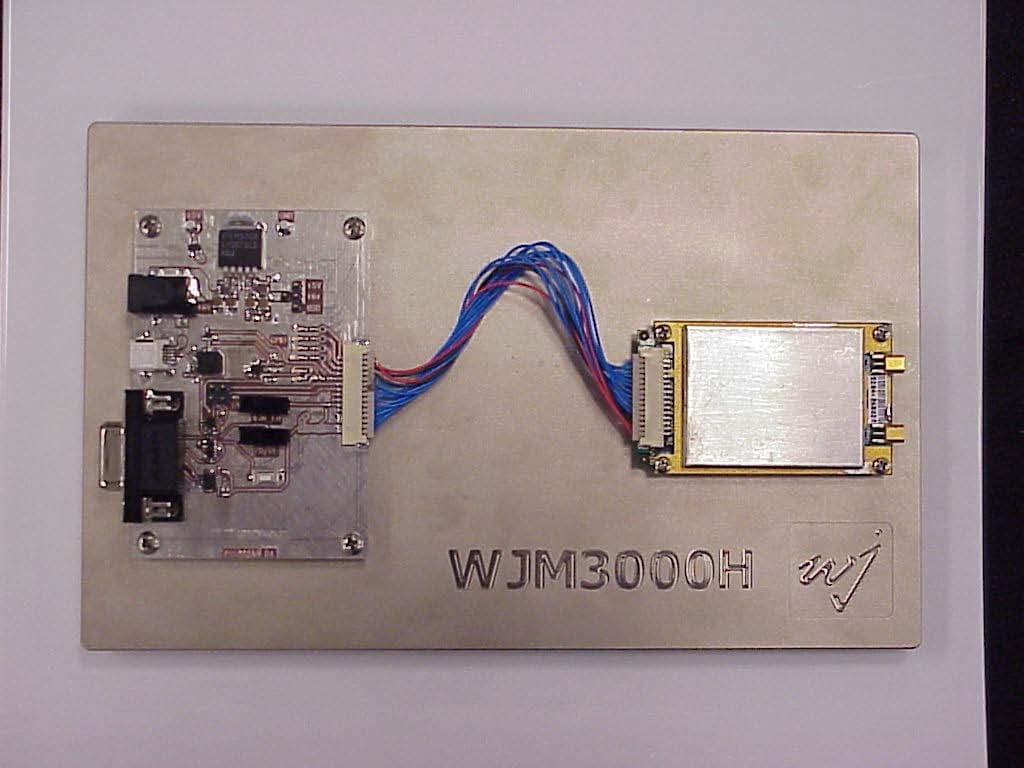
NTTWJM3000
Jan 11, 2007RFID Reader Module
Equipment Class
DSS - Part 15 Spread Spectrum Transmitter
NTTWJSR22XX
Sep 12, 2005902-928MHz RFID Reader
Equipment Class
DSS - Part 15 Spread Spectrum Transmitter
NTTWJMPR7XXX
Dec 12, 2004RFID Reader
Equipment Class
DSS - Part 15 Spread Spectrum Transmitter
NTTWJMPR6XXX
Dec 09, 2004RFID Reader
Equipment Class
DSS - Part 15 Spread Spectrum Transmitter
NTTWJMPR5XXX
Dec 09, 2004RFID Reader
Equipment Class
DSS - Part 15 Spread Spectrum Transmitter