NTTWJSR22XX902-928MHz RFID Reader
WJ Communications, Inc.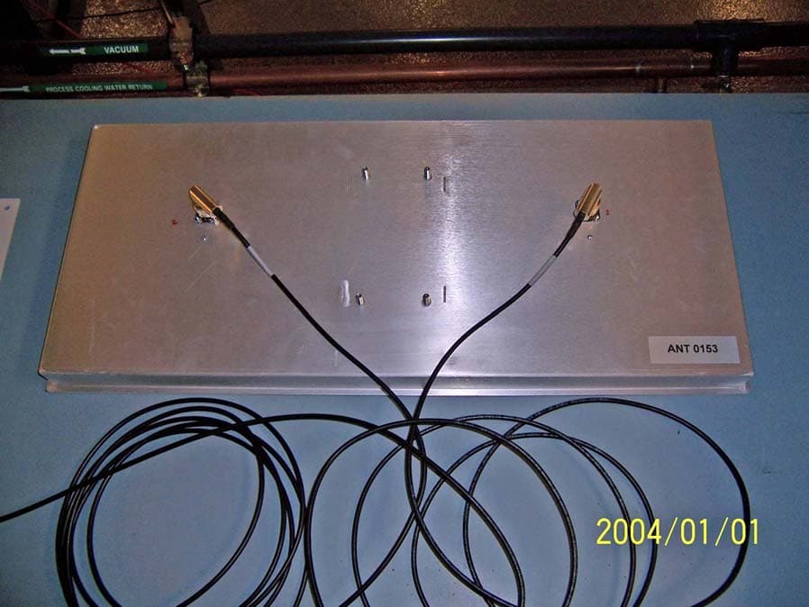
Click to zoom
Application Details
- Equipment Class
- DSS - Part 15 Spread Spectrum Transmitter
- Date of Grant
- Sep 12, 2005
- Application Purpose
- Original Equipment
- Date of Application
- Sep 12, 2005
- Equipment Note
- 902-928MHz RFID Reader
- Frequency Range
- 902.75000000 - 927.25000000
- Company
- WJ Communications, Inc.
- Country
- United States
Documents & Files
Document Text
Text extracted from the exhibit documents filed with the FCC. Open a document above to read the original.
Users Manual
Copyright© 2005 by WJ Communications Inc. Subject to change without notice. This information is provided “as is,” and WJ makes no claims of fit for purposes intended, merchantability or other. All trademarks, service marks, trade names and logos are used in good faith and remain the property of their rightful owners. page 1 1 Stationary RFID Portal Reader User’s Manual 1.1 Cover sheet Copyright© 2005 by WJ Communications Inc. Subject to change without notice. This information is provided “as is,” and WJ makes no claims of fit for purposes intended, merchantability or other. All trademarks, service marks, trade names and logos are used in good faith and remain the property of their rightful owners. page 2 1 STATIONARY RFID PORTAL READER USER’S MANUAL.........................1 1.1 Cover sheet ........................................................................................................................................ 1 1.2 Introduction ...................................................................................................................................... 3 1.2.1 Contents of this Document ......................................................................................................... 3 1.2.2 Audience..................................................................................................................................... 3 1.2.3 RFID System Quickstart............................................................................................................. 3 1.2.4 Product Description .................................................................................................................... 4 1.2.5 Unpacking and Inspection .......................................................................................................... 4 1.2.6 Product Installation..................................................................................................................... 4 1.3 Installation and Operation of demonstration Graphical User Interface ..................................... 5 1.3.1 Minimum System Requirements ................................................................................................ 5 1.3.2 Installation .................................................................................................................................. 5 1.3.3 Using the Demonstration software ............................................................................................. 8 1.3.4 COM Port Enumeration ............................................................................................................15 1.3.5 Changing Software Parameters and Reader Configuration ...................................................... 18 1.4 RFID overview ................................................................................................................................ 20 1.4.1 RFID operating principles ........................................................................................................ 20 1.4.2 RFID vs. bar code ..................................................................................................................... 22 1.4.3 RFID system components.........................................................................................................23 1.4.4 RFID standards ......................................................................................................................... 29 1.5 Stationary portal RFID Reader Theory of Operation................................................................. 39 1.6 Host-Reader Interface .................................................................................................................... 41 1.7 Troubleshooting / technical support .............................................................................................41 1.8 Technical specifications.................................................................................................................. 41 1.9 Notices.............................................................................................................................................. 42 1.9.1 RFID limitations ....................................................................................................................... 42 1.9.2 Safety........................................................................................................................................ 42 1.9.3 Limitation of liability................................................................................................................ 42 1.9.4 Patents....................................................................................................................................... 42 1.9.5 Copyright notice ....................................................................................................................... 42 1.9.6 Comments and feedback...........................................................................................................43 1.10 Regulatory Compliance.................................................................................................................. 43 1.10.1 FCC Statement.......................................................................................................................... 43 Copyright© 2005 by WJ Communications Inc. Subject to change without notice. This information is provided “as is,” and WJ makes no claims of fit for purposes intended, merchantability or other. All trademarks, service marks, trade names and logos are used in good faith and remain the property of their rightful owners. page 3 1.2 Introduction 1.2.1 Contents of this Document This manual describes installation and operation of the WJ Communications UHF Stationary RFID Portal Readers. A description of the installation and use of the demonstration Graphical User Interface is also provided. The Application Programmer’s Interface to the Apollo-series devices usin…
Text truncated - open the document above for the full version.
Block Diagram
WJSR22XX Block diagram
Cover Letter(s)
tel: 650-726-1263 fax: 650-726-1252 [email protected] Thomas N. Cokenias EMC &Radio Approvals Test & Consulting Services for Commercial, Military, International Compliance P.O. Box 1086 El Granada, CA 94018 Compliance Certification Services 30 August 2005 561 F Monterey Road Morgan Hill CA 95037 Attention: Mike Kuo Reviewing Engineer Applicant: WJ Communications Inc. FCC ID: NTTWJSR22XX Dear Mike, Request is hereby submitted, per section 0.459 of the Rules, on behalf of my client WJ Communications Inc., to withhold from public review certain portions of the application for equipment certification for the referenced FCC identifier. In particular, the following sections of the application and report are requested to be kept confidential: Schematic Rationale for request for confidentiality: WJ has invested considerable time and materials in research and development to produce the referenced product. Disclosure of the confidential portions of this application to competitors would give them competitive advantage in developing similar products. If you have questions or need further information, please contact the undersigned. Sincerely, THOMAS N. COKENIAS Agent for WJ Communications Inc.
Cover Letter(s)
1 Subject:FW: FW: WJ Communications, Inc., FCC ID: NTTWJSR22XX, Assessment NO.: AN05T5132, Notice#1 WJ22XXFCCRep2.d oc Hi Helen, Answers follow questions best regards Tom -----Original Message----- From: Compliance Certification Services [mailto:[email protected]] Sent: Friday, September 09, 2005 5:49 PM Subject: WJ Communications, Inc., FCC ID: NTTWJSR22XX, Assessment NO.: AN05T5132, Notice#1 Question #1: The antenna spec indicates the highest gain is 6.97dBi, but the test report indicates the device uses 6dBi gain antenna. Please clarify which one is correct. You may need to recalculate MPE with the correct antenna gain, if necessary, please update user manual for safety separation distance. ANS 1 The EUT uses a cable with a minimum attenuation of 1 dB, so the effective antenna gain at the transmitter port is 5.97 dBi, so EIRP is less than 36 dBm and using 6 dBi to calculate MPE is correct. See page 6 of updated test report, attached. Question #2: Test report shows some past due test equipment was used during the test. Please explain. ANS 2 There was a copy and paste error in the original report, the revised report has the correct cal dates Question #3: Based upon FCC Public Notice DA 00-705, for test items Carrier Frequency Separation and Number of hopping Frequencies, RBW must be equal or greater than 1% of the span, the plots in the report do not show this requirement is ever met. Please explain. ANS 3 The EUT modulation was such that a narrower bandwidth was needed to resolve the peaks. Since the purpose of the measurement is to distinguish peaks and distance between them and not bandwidth or power, bandwidth is not critical, and as such it is hoped the measurements can stand as they are. Question #4: Based upon FCC 15.247(a)(1)(i) "if the 20 dB bandwidth of the hopping channel is 250 kHz or greater... the average time of occupancy on any frequency shall not be greater than 0.4 seconds within a 10 second period." The test report shows with Class I mode, the 20dB bandwidth measurement is greater than 250MHz, but the report still uses 20 second period to calculate Time of Occupancy. 2 Please update the test report. ANS 4 The duration time has been calculated for 10 sec duration, see page 46 of the attached revised report Question #5: The test report Class I mode, 1.0mW/cm^2 instead of 0.6mW/cm^2 was used as Power density to calculate MPE. Please update the test report. ANS 5 All MPE calculations were made using an exposure value of 0.6 mW/cm2, the previous limit references have all been corrected. Best Regards, Helen Zhao > >The items indicated above must be submitted before processing can >continue on the above referenced application. Failure to provide the >requested information within 30 days of the original e-mail date may >result in application dismissal and forfeiture of the filing fee. >Also, please note that partial responses increase processing time >and should not be submitted. Any questions about the content of this >correspondence should be directed to the e-mail address listed below >the name of the sender.
External Photos
FCC ID: NTTWJSR22XX IC: 3374A-SR2200 WJ Communications RFID Reader FCC ID: NTTWJSR22XX Exterior Photographs TX and RX antenna ports FCC ID: NTTWJSR22XX IC: 3374A-SR2200 I/O, communications, and DC ports FCC ID: NTTWJSR22XX IC: 3374A-SR2200 Top view FCC ID: NTTWJSR22XX IC: 3374A-SR2200 Side view FCC ID: NTTWJSR22XX IC: 3374A-SR2200 Panel antenna connector side FCC ID: NTTWJSR22XX IC: 3374A-SR2200 Panel antenna transmit side
Internal Photos
FCC ID: NTTWJSR22XX IC: 3374A-SR2200 WJ Communications RFID Reader FCC ID: NTTWJSR22XX Interior Photographs All boards inside housing FCC ID: NTTWJSR22XX IC: 3374A-SR2200 Communications board and RF board removed from case FCC ID: NTTWJSR22XX IC: 3374A-SR2200 bottom RF board FCC ID: NTTWJSR22XX IC: 3374A-SR2200 Top, RF board FCC ID: NTTWJSR22XX IC: 3374A-SR2200 Communications board top FCC ID: NTTWJSR22XX IC: 3374A-SR2200 Communications board bottom FCC ID: NTTWJSR22XX IC: 3374A-SR2200 Control board bottom FCC ID: NTTWJSR22XX IC: 3374A-SR2200 Control board top
Operational Description
<protocolProp name="Delay" type="Integer">100</protocolProp> Note that the settings for the serial port can also be reset in this file. The default values are: - Port Number: COM1 - Baud Rate : 57600 - Data Bits : 8 - Stop Bits : 1 - Parity : NONE 1.1 RFID overview 1.1.1 RFID operating principles Radio-frequency identification (RFID) is an auto-identification technology, similar in concept to other common auto-identification technologies such as bar code scanners, magnetic strip readers, or magnetic ink readers. Like other auto-ID techniques. RFID associates an identifying number with a physical object. In RFID, the unique identifying number (UID or, as will be explained below, EPC) is incorporated in a special system, an RFID transponder (often simply known as a tag). An RFID Interrogator (usually known as a reader) is used to obtain the UID from the tag using electromagnetic waves. The tag is usually attached to a physical object that is to be identified, such as a carton, a pallet, or a container filled with a product. In order to reduce the cost of the tag, most tags do not incorporate a battery or other source of power, but instead operate using DC power derived from the radio frequency signal they receive from the reader. In addition, low-cost tags do not incorporate a radio transmitter, but instead use varying reflection of the received signal from the reader to communicate back to it. Such tags are known as passive tags. Since passive tags are the most common type, the description below will assume their use. Variants are also available: semi-active tags incorporate a battery to power the integrated circuit, but still use reflected waves (backscattering) to communicate with the reader. Active tags incorporate both a battery and a radio transmitter, and are much more costly than passive tags, but also more versatile. RFID systems can operate at different radio frequencies. The frequency chosen has important effects on the way tags and readers interact and on what applications are appropriate. Low-frequency (LF) tags and readers typically operate at 125 or 134 KHz. This is a very low frequency, with a wavelength of about 2.4 kilometers (1.5 miles). Low-frequency radiation is very effective at penetrating water and living tissues, so that LF tags can be used to identify livestock. However, because the tags and readers are very much smaller than a wavelength, they cannot radiate effectively, so LF readers and tags depend on inductive coupling to operate. In effect, the reader and tag form the primary and secondary windings of a transformer. The tag must be in close proximity to the reader antenna to be read; read ranges are comparable to the size of the reader antenna, typically a few 10’s of cm (5-10 inches) for a small reader antenna. Because the induced voltage per coil winding is also very small at these frequencies, the tags are composed of many turns of wire, often wound around a ferrite core to increase coupling. Since there is no radiated power, there is usually very little issue with regulatory compliance in using LF tags and readers. High-frequency (HF) tags and readers operate at 13.56 MHz. This frequency is available for industrial use in most jurisdictions worldwide. The wavelength is about 20 meters (60 feet), still larger than most reader or tag antennas, so inductive coupling is used as in LF tags and readers. However, the higher frequency provides a larger induced voltage, so the reader usually uses a single-turn coil, and transponders typically incorporate 3-5 turns of wire. HF transponders can be readily constructed on a flat plastic substrate the size of a credit card, forming Smart Cards widely used as identification badges and credit cards with enhanced functionality. Typical read range varies from a few cm to a meter or so (a few inches to 3 feet), again dependent on reader antenna size. When long read range is required, ultra-high-frequency (UHF) tags and readers are appropriate. The Apollo-series are UHF RFID readers. UHF systems typically operate at frequencies between 860 and 960 MHz, depending on the regulatory jurisdiction. In the United States, unlicensed operation is allowed in the Industrial, Scientific, and Medical (ISM) band at 902-928 MHz. The wavelength at these frequencies is about 33 cm (13 inches), so the reader and tags are roughly comparable in size to the wavelength. The reader antenna creates a radiated electromagnetic wave, which can propagate long distances. UHF tags and readers can thus exploit radiative coupling to achieve read ranges not available for LF or HF devices. Read range for passive UHF tags can be as much as 10 meters (30 feet) with an appropriate directional antenna; longer ranges are achievable using semi-passive tags. RFID readers and tags operating in the microwave ISM band at 2.4-2.45 GHz are also widely used. The 2.4-2.45 GHz band is available for unlicensed operation in most jurisdictions worldwide. At this frequency the wavelength is about 12 cm (5 inches). Very small tags can be used in the 2.45 GHz band, but because of the consequent small antennas, the amount of power collected by a tag is reduced in comparison to UHF tags. Passive 2.4 GHz tags have typical read ranges of around 1 to 3 meters (3 to 10 feet). 1.1.2 RFID vs. bar code RFID tags and readers perform functions similar to those of bar codes and bar code scanners. How do they differ? When should one use bar codes and when should RFID tags be employed? There are four key distinctions to keep in mind: • COST: bar codes can be printed on the surface of many existing packages at very low cost. Separate bar-coded tags with adhesive backing are also inexpensive. Bar code scanners of various types are widely available at modest cost, as is software to integrate bar code scanning into standard business processes and enterprise planning. RFID (particularly at UHF and microwave frequencies) is a relatively less widespread technology, and RFID tags are manufactured ob…
Text truncated - open the document above for the full version.
Test Report
FCC CFR47 PART 15 SUBPART C Test Report 902-928 MHZ RFID READER Model Numbers: SR2200, SR2204 FCC ID: NTTWJSR22XX Report Number: 05WJ22XXFCC Issue Date: August 29, 2005 Prepared for WJ Communications Inc. 401 River Oaks Parkway San Jose 95134 Prepared by T.N. Cokenias Consulting P.O. Box 1086 El Granada CA 94018 Report No: 05WJ22XXFCCDate: 29 AUGUST 2005 902-928 MHz RFID reader FCC ID: NTTWJSR22XX Page 2 of 105 TABLE OF CONTENTS 1.TEST AND TEST LOCATION INFORMATION...............................................................................4 2.TEST METHODOLOGY.........................................................................................................................5 3.EQUIPMENT UNDER TEST..................................................................................................................5 3.1.DESCRIPTION OF EUT.....................................................................................................................5 3.2.MAXIMUM OUTPUT POWER..........................................................................................................5 3.3.DESCRIPTION OF AVAILABLE ANTENNAS..................................................................................6 3.4.SOFTWARE AND FIRMWARE..........................................................................................................7 3.5.WORST-CASE CONFIGURATION AND MODE..............................................................................7 3.6.DESCRIPTION OF TEST SETUP......................................................................................................8 3.7Modifications to EUT..........................................................................................................................9 TEST AND MEASUREMENT EQUIPMENT...............................................................................................10 4.LIMITS AND RESULTS........................................................................................................................11 4.1.ANTENNA PORT CHANNEL TESTS FOR CLASS 0 MODULATION.........................................11 4.1.1.20 dB BANDWIDTH...............................................................................................................11 HOPPING FREQUENCY SEPARATION..............................................................................................15 4.1.2.NUMBER OF HOPPING CHANNELS..................................................................................17 4.1.3.AVERAGE TIME OF OCCUPANCY....................................................................................19 4.1.4.MAXIMUM PERMISSIBLE EXPOSURE.............................................................................26 4.1.5.CONDUCTED SPURIOUS EMISSIONS...............................................................................29 4.2.ANTENNA PORT CHANNEL TESTS FOR CLASS 1 MODULATION.........................................38 4.2.1.20 dB BANDWIDTH...............................................................................................................38 4.2.2.HOPPING FREQUENCY SEPARATION.............................................................................42 4.2.3.NUMBER OF HOPPING CHANNELS..................................................................................44 4.2.4.AVERAGE TIME OF OCCUPANCY....................................................................................46 4.2.5.PEAK OUTPUT POWER........................................................................................................49 4.2.6.MAXIMUM PERMISSIBLE EXPOSURE.............................................................................53 4.2.7.CONDUCTED SPURIOUS EMISSIONS...............................................................................56 4.3.ANTENNA PORT CHANNEL TESTS FOR MODE 1800 MODULATION..................................65 4.3.1.20 dB BANDWIDTH...............................................................................................................65 4.3.2.HOPPING FREQUENCY SEPARATION.............................................................................69 4.3.3.NUMBER OF HOPPING CHANNELS..................................................................................71 4.3.4.AVERAGE TIME OF OCCUPANCY....................................................................................73 4.3.5.PEAK OUTPUT POWER........................................................................................................76 4.3.6.MAXIMUM PERMISSIBLE EXPOSURE.............................................................................80 4.3.7.CONDUCTED SPURIOUS EMISSIONS...............................................................................83 4.4.RADIATED EMISSIONS...................................................................................................................92 4.4.1.TRANSMITTER RADIATED SPURIOUS EMISSIONS.....................................................92 4.4.2.TRANSMITTER RADIATED EMISSIONS ABOVE 1 GHZ HARMONICS AND SPURIOUS EMISSIONS..........................................................................................................................95 Report No: 05WJ22XXFCCDate: 29 AUGUST 2005 902-928 MHz RFID reader FCC ID: NTTWJSR22XX Page 3 of 105 1.WORST-CASE RADIATED EMISSIONS BELOW 1 GHz..........................................................96 4.5.POWERLINE CONDUCTED EMISSIONS......................................................................................98 5.SETUP PHOTOS...................................................................................................................................101 Report No: 05WJ22XXFCCDate: 29 AUGUST 2005 902-928 MHz RFID reader FCC ID: NTTWJSR22XX Page 4 of 105 1. TEST AND TEST LOCATION INFORMATION COMPANY NAME:WJ COMMUNICATIONS 401 RIVER OAKS PARKWAY SAN JOSE, CA 95134 EUT DESCRIPTION:RFID READER CARD MODEL:SR2200 DATA ALSO APPLIES TO : SR2201 DATE TESTED:JUNE 23 – AUGUST 5 2005 All tests were performed by Co…
Text truncated - open the document above for the full version.
Test Setup Photos
FCC ID: NTTWJSR22XXIC: 3374A-SR2200 WJ Communications RFID Reader FCC ID: NTTWJSR22XX Test Setup photographs FCC ID: NTTWJSR22XXIC: 3374A-SR2200 FCC ID: NTTWJSR22XXIC: 3374A-SR2200 multi pin I/O cable FCC ID: NTTWJSR22XXIC: 3374A-SR2200 FCC ID: NTTWJSR22XXIC: 3374A-SR2200
Contact Information
Applicant
Tim Buchner(Strategic Marketing)
Test Firm
Compliance Certification Services IncSteve Cheng
Technical Specifications
| # | Rule Parts | Frequency Range | Power Output |
|---|---|---|---|
| 1 | 15C | 902.75 MHz - 927.25 MHz | 935.40 mW |
Other Applications from WJ Communications, Inc.
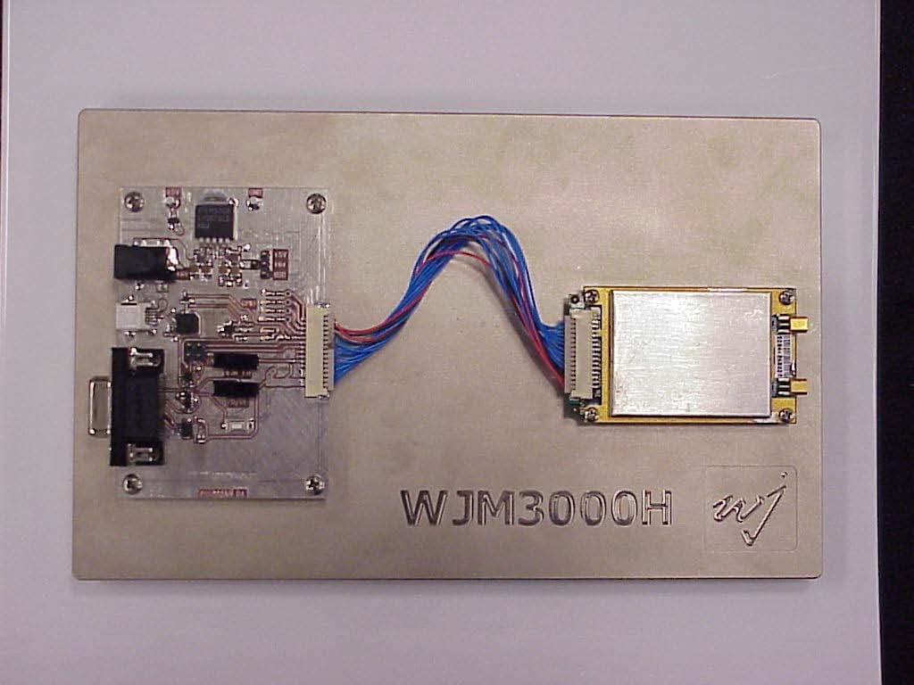
NTTWJM3000
Jan 11, 2007RFID Reader Module
Equipment Class
DSS - Part 15 Spread Spectrum Transmitter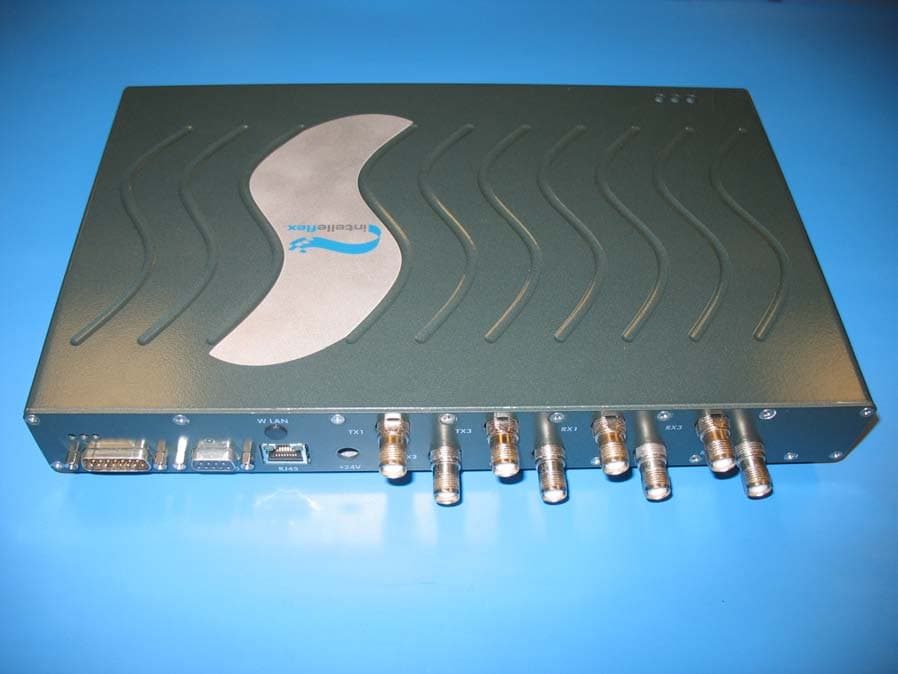
NTTSR320
Jun 20, 2006RFID Tag Reader
Equipment Class
DSS - Part 15 Spread Spectrum Transmitter
NTTWJMPR7XXX
Dec 12, 2004RFID Reader
Equipment Class
DSS - Part 15 Spread Spectrum Transmitter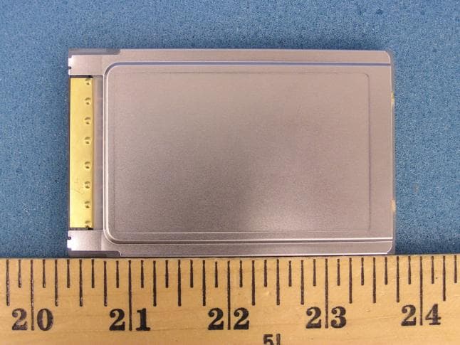
NTTWJMPR6XXX
Dec 09, 2004RFID Reader
Equipment Class
DSS - Part 15 Spread Spectrum Transmitter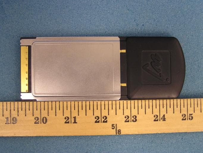
NTTWJMPR5XXX
Dec 09, 2004RFID Reader
Equipment Class
DSS - Part 15 Spread Spectrum Transmitter