NTTWJM3000RFID Reader Module
WJ Communications, Inc.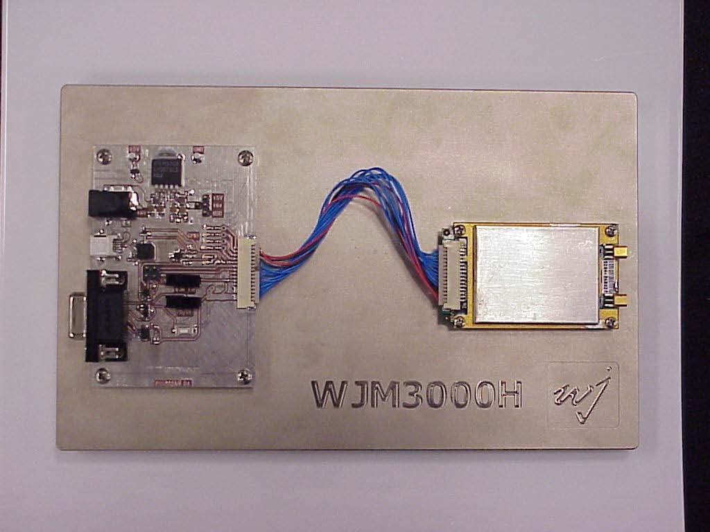
Click to zoom
Application Details
- Equipment Class
- DSS - Part 15 Spread Spectrum Transmitter
- Date of Grant
- Jan 11, 2007
- Application Purpose
- Original Equipment
- Date of Application
- Jan 11, 2007
- Equipment Note
- RFID Reader Module
- Frequency Range
- 902.75000000 - 927.25000000
- Company
- WJ Communications, Inc.
- Country
- United States
Documents & Files
Document Text
Text extracted from the exhibit documents filed with the FCC. Open a document above to read the original.
Users Manual
WJM Series User’s Manual V01.00 www.wj.com 1/12/07 Page 1 WJ Module (WJM) Reader Modules User’s Manual Version 1.0 WJ Communications, Inc. 401 River Oaks Pkwy San Jose, CA 94089 Tel: (800) WJ1-4401 Fax: (408) 577-6621 http://www.wj.com WJM Series User’s Manual V01.00 www.wj.com 1/12/07 Page 2 Disclaimer: This information is subject to change without notice. This information is provided “as is,” and WJ makes no claims of it for purposes intended, merchantability or other. All trademarks, service marks, trade names and logos are used in good faith and remain the property of their rightful owners. For actual design-in, refer to the latest publications of WJ Communications data sheets for the most up-to-date specifications of WJ Communications products. Not all products and/or types are available in every country. Please check with a WJ sales representative or distributorship for availability and additional information. No part of this document may be copied or reproduced in any form or by any means without prior written consent of WJ Communications. WJ Communications assumes no responsibility for any errors that may appear in this document. WJ Communications does not assume any liability for infringement of patents, copyrights or other intellectual property rights of third parties by or arising from the use of WJ Communications products listed in this document or any other liability arising from the use of such WJ Communications products. No license, express, implied or otherwise, is granted under any patents, copyrights or other intellectual property rights of WJ Communications or others. Descriptions of circuits, software and other related information in this document are provided for illustrative purposes in semiconductor product operation and application examples. The incorporation of these circuits, software and information in the design of customer's equipment shall be done under the full responsibility of customer. WJ Communications no responsibility for any losses incurred by customers or third parties arising from the use of these circuits, software and information. While WJ Communications endeavors to enhance the quality, reliability and safety of WJ Communications products, customers agree and acknowledge that the possibility of defects thereof cannot be eliminated entirely. To minimize risks of damage to property or injury (including death) to persons arising from defects in WJ Communications products, customers must incorporate sufficient safety measures in their design, such as redundancy, fire-containment and anti-failure features. Copyright© 2006 WJ Communications Inc. November 2006. Revision History: The following table shows the revision history for this document. Version Date By Revision 1.0 11/29/06 BEC Initial Release WJM Series User’s Manual V01.00 www.wj.com 1/12/07 Page 3 Conventions: WARNING: A warning is used where care must be taken or a certain procedure must be followed, in order to prevent injury or harm to your health. Caution: A caution indicates information on conditions that must be met or a procedure that must be followed, that if not heeded could cause permanent damage to the equipment or software. Note: A note indicates conditions that must be met or procedures that must be followed to ensure proper functioning of the equipment or software. Information: An informational alert indicates items that make usage of the equipment or software easier. WJM Series User’s Manual V01.00 www.wj.com 1/12/07 Page 4 Table Of Contents 1 Introduction......................................................................................................6 1.1 Contents of this Document........................................................................6 1.2 Audience...................................................................................................6 2 Product Description.........................................................................................7 2.1 WJM1000..................................................................................................7 2.2 WJM3000..................................................................................................7 2.3 WJM Multi Interface Board (MIB)..............................................................7 3 WJM Antennas................................................................................................8 4 Using the WJM................................................................................................9 4.1 Hardware Installation................................................................................9 4.2 Communications.......................................................................................9 4.3 Connector Pinout......................................................................................9 4.4 User Interface Demo...............................................................................10 4.4.1 Installation........................................................................................10 4.5 Application Programmers Interface (API)................................................10 4.5.1 .NET DLL (Dynamic Link Library).....................................................10 4.5.2 WJM Example DLL Project...............................................................11 4.6 Upgrade Utility........................................................................................11 5 Compatibility..................................................................................................12 5.1 Host........................................................................................................12 5.2 Tags........................................................................................................12 6 Troubleshooting / Technical Support.............................................................13 6.1 General...................................................................................................13 6.2 …
Text truncated - open the document above for the full version.
Cover Letter(s)
Company: WJ Communications FCC ID: NTTWJM3000 Request for transmitter modular approval Transmitter Module Characteristics Item Requirements EUT(sample answer) 1 Have its own RF shielding Device is equipped with Metal shielding to cover RF section. Refer to external photos 2 Have buffered modulation/data inputs (if such inputs are provided), All inputs to the modules are buffered through logic or microprocessor inputs. 3 Have it own power supply regulation Internal 1.8V power regulator. 4 Meet the antenna requirements of Section 15.203 Device is equipped with unique antenna connector (MMCX). Refer to external photos 5 Be tested in a stand-alone configuration, i.e., the antenna, AC or DC power and data input/output lines must be connected to the module but, the module must not be inside another case during testing Device was mounted and tested on an open heat sink. Refer to setup photos. 6 Be labeled with its own FCC ID number, and if the FCC ID is not visible when the module is installed inside another device, then the outside of the device into which the module is installed must also display a label referring to the enclosed module. Two proposed FCC ID label format are included in the filing. One of label is to be placed on the module and the other label is to be placed on the outside of system. Refer to FCC ID label format and location file. 7 The modular transmitter is manufactured so that the user cannot influence the operation of the transmitter that will operate outside of the scope of the regulations. Refer to “User’s Guide” Exhibit 8 Address compliance with the Commission's RF exposure limits in Sections 1.1310 and 2.1093. In addition, spread spectrum transmitters operating under Section 15.247 are required to address RF exposure compliance in accordance with Section 15.247(b)(4). MPE calculated at approximately 17.5cm.
Cover Letter(s)
WJ COMMUNICATIONS INC, FCC ID: NTTWJM3000, Assessment NO.: AN06T6406, Notice#1 Inbox Reply from "[email protected]" <[email protected]> hide details Jan 3 to [email protected] cc [email protected] date Jan 3, 2007 9:40 PM subject WJ COMMUNICATIONS INC, FCC ID: NTTWJM3000, Assessment NO.: AN06T6406, Notice#1 Dear Tom, The technical review is complete. Please reply to the following issues. Q1. Models WJM-H, WJM-F, and WJM-P are described in the user manual. Please clarify which model(s) are addressed in this application. In the user manual, handheld operation is mentioned for the WJM-F. Please provide clarification and include specific information with regard to RF exposure in the user manual if handheld operation is intended. Q2. Please provide justification for the test configuration on the metal heatsink. Item 1 of DA 00-1407 requires testing in a standalone configuration. If a heatsink such as the one tested is part of the product as sold or if user instructions require use of such a heatsink, then the test configuration could be considered justified. Please provide additional information and revised user installation instructions as appropriate. Q3. The operational description submitted is an overview of RFID technology in general. Please submit an operational description specific to this application including information required by 2.1033(b)(4): A brief description of the circuit functions of the device along with a statement describing how the device operates. This statement should contain a description of the ground system and antenna, if any, used with the device. (Refer also to item Q7 below) Q4. Please revise section 4.1.3 of the test report to show calculations or describe how the occupancy time was calculated . Following are examples taken from reports in the FCC database: EXAMP 1: The maximum duration of the RF transmission is 364ms during a 700ms channel dwell time. There is a minimum of 50 channels used during the hopping sequence therefore a channel will not be re-occupied until at least 35s. Therefore the average time of occupancy on any one channel in a 20 second period is 364ms.. A detailed description of the RF timing and a timing diagram are included in the theory of operation. EXAMP 2:Each transmission is 5.887 mS long. Each transmission takes place on one of 50 different channels in a pseudo-random sequence. All 50 channels are used equally on the average. The algorithm that determines the pseudo-random hop sequence does not allow the device to transmit on the same channel more than once in a 20 second period. 5. Please provide the second label format referred to in the modular request letter. 6. Please provide an antenna list and specifications exhibit. Antenna type, model number, gain, and connector type for each antenna should be included. 7. Please address the requirements of 15.247(g) 15.247(h) and in the operational description or test report. Best regards, Tim Dwyer CCS Technical Reviewer The items indicated above must be submitted before processing can continue on the above referenced application. Failure to provide the requested information within 30 days of the original e-mail date may result in application dismissal and forfeiture of the filing fee. Also, please note that partial responses increase processing time and should not be submitted. Any questions about the content of this correspondence should be directed to the e-mail address listed below the name of the sender. Reply Reply to all Forward Invite [email protected] to Gmail Reply from Thomas Cokenias <[email protected]> hide details Jan 8 (4 days ago) to "<[email protected]>" <[email protected]> date Jan 8, 2007 7:26 PM subject Re: WJ COMMUNICATIONS INC, FCC ID: NTTWJM3000, Assessment NO.: AN06T6406, Notice#1 Hi Tim, and Happy New Year! Answers follow questions. I'm in the office most of this week. best regards Tom office 650 726 1263 On Jan 3, 2007, at 6:40 PM, <[email protected] > <[email protected]> wrote: > Dear Tom, > > The technical review is complete. Please reply to the following > issues. > > Q1. Models WJM-H, WJM-F, and WJM-P are described in the user > manual. Please clarify which model(s) are addressed in this > application. In the user manual, handheld operation is mentioned > for the WJM-F. Please provide clarification and include specific > information with regard to RF exposure in the user manual if > handheld operation is intended. ANS1 The user manual has been corrected to reference the two models that will be sold: WJM1000 (24dBm max output power) and WJM3000 (30dBm maximum output power). The antennas used with either model will always be located at least 20cm from all persons, as described in the installation manual. > > Q2. Please provide justification for the test configuration on the > metal heatsink. Item 1 of DA 00-1407 requires testing in a > standalone configuration. If a heatsink such as the one tested is > part of the product as sold or if user instructions require use of > such a heatsink, then the test configuration could be considered > justified. Please provide additional information and revised user > installation instructions as appropriate. ANS2 In the revised user manual, WJ recommends that the module be mounted on a heat sink. The heat sink used during testing is representative of a typical heat sink, but it is expected that integrators will use as heat sinks the metal cases that usually house devices of this type. > > Q3. The operational description submitted is an overview of RFID > technology in general. Please submit an operational description > specific to this application including information required by > 2.1033(b)(4): A brief description of the circuit functions of the > device along with a statement describing how the device operates. > This statement should contain a description of the ground system > and antenna, if any, used with the device. (Refer also to item Q7 > below) ANS3 A revised operational description is attac…
Text truncated - open the document above for the full version.
Cover Letter(s)
Thomas N. Cokenias EMC &Radio Approvals Test & Consulting Services for Commercial, Military, International Compliance P.O. Box 1086 El Granada, CA 94018 Compliance Certification Services 22 December 2006 561 F Monterey Road Morgan Hill CA 95037 Attention: Mike Kuo Reviewing Engineer Applicant: WJ Communications Inc. FCC ID: NTTWJM3000 Dear Mike, Request is hereby submitted, per section 0.459 of the Rules, on behalf of my client WJ Communications Inc., to withhold from public review certain portions of the application for equipment certification for the referenced FCC identifier. In particular, the following sections of the application and report are requested to be kept confidential: Schematic Block Diagram Operational description Rationale for request for confidentiality: WJ has invested considerable time and materials in research and development to produce the referenced product. Disclosure of the confidential portions of this application to competitors would give them competitive advantage in developing similar products. If you have questions or need further information, please contact the undersigned. Sincerely, THOMAS N. COKENIAS Agent for WJ Communications Inc. tel: 650-726-1263 fax: 650-726-1252 [email protected]
External Photos
WJM3000 WJM3000 on with MIB, connecting wires, secured to plate WJM3000 Top (unshielded) WJM3000 Bottom (unshielded) WJM3000 Top (shielded) WJM3000 Bottom (unshielded) (Optional vertical antenna port included) WJM3000 Side (Optional vertical antenna port included)
ID Label/Location Info
WJ Communications FCC ID: NTTWJM3000 Label and label location FCC ID: NTTWJM3000 IC: 3374A-WJM3000 Model No.: WJM3000 Label format for Integrated Product Housing RF Module Contains FCC ID: NTTWJM3000 IC: 3374A-WJM3000 Model No.: WJM3000
Internal Photos
WJM3000 WJM3000 on with MIB, connecting wires, secured to plate WJM3000 Top (unshielded) WJM3000 Bottom (unshielded) WJM3000 Top (shielded) WJM3000 Bottom (unshielded) (Optional vertical antenna port included) WJM3000 Side (Optional vertical antenna port included)
Parts List/Tune Up Info
Symbol Technologieshttp://www.symbol.com/assets/tools/print.html 1 of 31/10/2007 10:22 AM Highlights Sign Up for the RFID Newsletter Read about Real-world RFID Deployments Create superior read zones throughout your enterprise Symbol's General Purpose Indoor/Outdoor Radio Frequency Identification (RFID) Antennas can be used reliably in a wide range of indoor and outdoor environments from the warehouse to the production line to the docking zone. Additional benefits: Rugged design withstands environmental conditions such as extreme heat and cold, as well as moisture and vibration. All-purpose antenna can be used in both standard RFID applications at power levels of up to one watt and in customized applications at power levels up to 20 watts. Comprehensive RFID Antenna Portfolio Radio Frequency Identification (RFID) Antennas from Symbol Technologies offer versatility and performance to meet diverse application needs. When used in conjunction with Symbol’s RFID systems, communication with Electronic Product Code (EPC™)-compliant RFID tags is accurate, fast and efficient. Antennas are a vital component in reader-tag communications. General Purpose Antenna for Indoor or Outdoor Applications Get the convenience of a versatile antenna that can be utilized throughout your enterprise, from the warehouse floor and production line to outside the dock door. Able to withstand extreme heat and cold as well as moisture and vibration, this antenna is ideal for nearly any application, including retail, manufacturing, wholesale distribution, healthcare, government and more. This all-purpose antenna can be used in standard RFID applications with power levels up to one watt, as well as custom high-power applications requiring up to 20 watts. The antenna is traditionally used in pairs, with right and left hand polarization. Symbol RFID Antennas – A Vital RFID System Component RFID Antennas complement the portfolio of Symbol enterprise mobility solutions that enable organizations to capture, move and manage critical information to and from every point of business activity. These efficient antennas are ideal for high-throughput, highcapacity communication of EPC-compliant RFID tag data. For more information, contact us at +1.800.722.6234 or +1.631.738.2400, or visit us on the web at www.symbol.com. Services for a More Successful Mobility Solution Symbol offers a full suite of services, including complete analysis, design, installation, training and ongoing support for the seamless deployment, management and continued support of your RFID solution. Specification Highlights General Purpose Indoor-Outdoor Antenna Physical Characteristics Dimensions: 11.1 in. L x 11.1 in. W x 1.9 in. D /28.19 cm L x 28.19 cm W x 4.83 cm D Weight: 3 lbs/1.26 kg Close RFID Home > Products > RFID > Fixed RFID Reader Antennas > AN200 General Purpose RFID Antennas AN200 General Purpose RFID Antennas Symbol Technologieshttp://www.symbol.com/assets/tools/print.html 2 of 31/10/2007 10:22 AM Specifications are subject to change without notice. All product and company names are trademarks, service marks or registered trademarks of their respective owners. For system, product or services availability and specific information within your country, please contact your local Symbol Technologies office or Business Partner. Part No. RFID Antenna_DS Printed in USA 03/06 © Copyright 2005 Symbol Technologies, Inc. All rights reserved. Symbol is an ISO 9001 and ISO 9002 UKAS, RVC, and RAB Registered company, as scope definitions apply. Specifications are subject to change without notice. All product and company names are trademarks, service marks or registered trademarks of their respective owners. For system, product or services availability and specific information within your country, please contact your local Symbol Technologies office or Business Partner. User Environment Operating Temperature: -40° to +149° F/-40° to +65° C Cold Test: IEC-68-2-1 (-40° F/-40° C for 24 hours) Heat Test: IEC-68-2-2 (158° F/70° C for 24 hours) Temperature Shock Test: IEC-68-2-14 (-40° F rising to 158° F/ -40° C rising to 70° C in 10 cycles of 60 minutes each) Humidity Test: IEC-68-2-30 (77° to 104° F/-25° to 40° C 24 hour cycles of 90% relative humidity Rain Test: IEC-68-2-18 (8 hours minimum in rain chamber at 43 psi) Salt Fog Test: IEC-68-2-11 (96 hours, repetitive cycling) Random Vibration Test: IEC-68-2-6 (10 to 150 Hz, 05 g, 1 hour in each of 2 axes) Electrical Characteristics Frequency Range: 900-928 MHz Nominal Impedence:50 Ohm Impedence, DC: 10 kOhm +/- 5% Gain in dBi linear: 6.0 Polarization:Right and left-hand circular polarization Axial Ratio at Boresight: < 3 db AZ, EL BW: 60 degrees Front to Back Ratio:< 10 db Return Loss (VSWR): 20 dB (1.22) Maximum Input Power: 20 watts NOTICE: Repairs of these products may require the use of Symbol proprietary parts (and/or Symbol proprietary information). Symbol will sell these parts (and provide this proprietary information) only to end-user customers for self-service. Applicable in the U.S. For all other countries, please contact your Symbol account manager or the local Symbol Customer Service representative in your area for further details. About Symbol Technologies Symbol Technologies, Inc., The Enterprise Mobility Company™, is a recognized worldwide leader in enterprise mobility, delivering products and solutions that capture, move and manage information in real time to and from the point of business activity. Symbol enterprise mobility solutions integrate advanced data capture products, radio frequency identification technology, mobile computing platforms, wireless infrastructure, mobility software and world-class services programs. Symbol enterprise mobility products and solutions are proven to increase workforce productivity, reduce operating costs, drive operational efficiencies and realize competitive advantages for the world's leading companies. White Papers Business Benefits from Radio Frequency Identifica…
Text truncated - open the document above for the full version.
Parts List/Tune Up Info
WJA0001 806-960MHz Directional Panel Antenna General Specifications: Directional panel antenna Radome Material: UL 94-V0 plastic Polarization: Linear, Vertical/Horizontal Nominal Impedance: 50O Specifications: Frequency Range Gain Front- to- Back Ratio 3dB Horizontal Beam Width 3dB Vertical Beam Width VSWR Maximum Output Power Connector 806- 960MHz 6.0dBi >19dB 70 o 60 o <1.5:1 20 Watts SMA *Note: The WJA0001 is a MaxRad MP8066XFPTM Panel antenna with an additional WJ Equalizer Network added. This Equalizer Network consists of a 2.1dB attenuation permanently fixed to the input of the antenna thereby toning the overall linear gain of the antenna to 6.0dBi XtremeWave™ XF Series General Specifications: Directional panel antennas Radome Material: UL 94-V0 plastic Polarization: Linear, vertical/horizontal (all models but MP9026CPLXFPT and MP9026CPRXFPT) Left hand circular (MP9026CPLXFPT only) Right hand circular (MP9026CPRXFPT only) Nominal Impedance: 50 Ohms Mounting Method: The XtremeWave™ directional panel antennas are designed to cover 800/900 MHz frequencies with a VSWR of less than 1.5:1, obtaining maximum gain with an attractive, low-profile package. All models provide efficient and stable perfor- mance across the band and can be mounted indoors or outdoors. Features and Benefits: •Highly efficient antenna element provides high performance in an attractive, compact housing. •UL94-V0 plastic and PC board. Provides UL’s highest flame retardant rating allowing maximum placement flexibility. Meets the most stringent building fire rating codes. •Attractive, low profile housing. Blends well with indoor and outdoor environments where aesthetic considerations are important. •Corner exit, high performance RG-58/U pigtail design. Permits the linear polarized panel to be mounted in vertical or horizontal polarity with a wide variety of connectors. •Optional UL 910 rated Plenum cable. Allows the cable to be installed in the strictest indoor mounting locations, including air ducts. •Optional adjustable mounting brackets for indoor and outdoor mounting. Provide maximum flexibility for indoor or outdoor installations. 800/900 MHz Directional Panel Antenna Series Model/MountMPAB7MPAB8MPAB11MPAB12 All modelsoptionaloptionaloptionaloptional Mount Description Heavy duty outdoor adjustable mount with +/-35° uptilt/downtilt. Same as MPAB8 but bracket is longer. Heavy duty outdoor adjustable mount with 17° uptilt/downtilt. Short adjustable indoor mount. Long adjustable indoor wall corner mount. The XtremeWave™ directional panels feature a UV resistant, UL94-V0 plastic housing that meets UL’s highest flame retardant rating for maximum placement flexibility. These panels meet stringent building fire rating codes for in-building installations, and can also be safely installed outdoors. Product shown with optional MPAB12 long adjustable indoor wall corner mount (above) and optional MPAB8 heavy duty adjustable outdoor mast mount. 203 PCTEL Antenna Products Group, Inc. ORDER (800) 323-9122 http://www.maxrad.com Model # Frequency RangeGain Front-to- Back Ratio 3 dB Horizontal Beamwidth 3 dB Vertical BeamwidthVSWR Maximum Power Input Connector Options MP8066XFPT806-960 MHz8.1 dBi> 17 dB70°60°< 1.5:120 Watts N female (part #NF) standard. Other options are available. MP8906XFPT890-960 MHz8.6 dBi> 17 dB70°60°< 1.5:120 Watts MP9027XFPT902-928 MHz9.1 dBi> 17 dB65°65°< 1.5:120 Watts MP9026CPLXFPT902-928 MHz8.5 dBic> 20 dB65°65°< 1.5:120 Watts MP9026CPRXFPT902-928 MHz8.5 dBic> 20 dB65°65°< 1.5:120 Watts Model # Wind Loading (Frontal) @100 mph Wind Temperature RangeDimensionsWeightHigh Performance Cable MP8066XFPT27.9 lbs.-40°C to +70°C 8.8” x 8.1” x 1.6” (22.4 x 20.6 x 4.06 cm) 1.2 lbs (0.54 kg) 12” (30.5 cm) RG58/U* MP8906XFPT27.9 lbs.-40°C to +70°C 8.8” x 8.1” x 1.6” (22.4 x 20.6 x 4.06 cm) 1.2 lbs (0.54 kg) 12” (30.5 cm) RG58/U* MP9027XFPT27.9 lbs.-40°C to +70°C 8.8” x 8.1” x 1.6” (22.4 x 20.6 x 4.06 cm) 1.2 lbs (0.54 kg) 12” (30.5 cm) RG58/U* MP9026CPLXFPT27.9 lbs.-40°C to +70°C 8.8” x 8.1” x 1.6” (22.4 x 20.6 x 4.06 cm) 1.2 lbs (0.54 kg) 12” (30.5 cm) RG58/U* MP9026CPRXFPT27.9 lbs.-40°C to +70°C 8.8” x 8.1” x 1.6” (22.4 x 20.6 x 4.06 cm) 1.2 lbs (0.54 kg) 12” (30.5 cm) RG58/U* * UL910 rated cable optional. Mechanical Specifications Specifications 204 PCTEL Antenna Products Group, Inc. ORDER (800) 323-9122 http://www.maxrad.com Electrical Specifications 205 MP8066XFPT Azimuth Cut MP8066XFPT Elevation Cut 10 190 20 200 30 210 40 220 50 230 60 240 70 250 80 260 90 270 100 280 110 290 120 300 130 310 140 320 150 330 160 340 170 350 1800 3535 3030 2525 2020 1515 1010 55 10 190 20 200 30 210 40 220 50 230 60 240 70 250 80 260 90 270 100 280 110 290 120 300 130 310 140 320 150 330 160 340 170 350 1800 3535 3030 2525 2020 1515 1010 55 Patterns PCTEL Antenna Products Group, Inc. ORDER (800) 323-9122 http://www.maxrad.com MP8906XFPT Azimuth Cut MP8906XFPT Elevation Cut 10 190 20 200 30 210 40 220 50 230 60 240 70 250 80 260 90 270 100 280 110 290 120 300 130 310 140 320 150 330 160 340 170 350 1800 3535 3030 2525 2020 1515 1010 55 10 190 20 200 30 210 40 220 50 230 60 240 70 250 80 260 90 270 100 280 110 290 120 300 130 310 140 320 150 330 160 340 170 350 1800 3535 3030 2525 2020 1515 1010 55 Patterns 206 PCTEL Antenna Products Group, Inc. ORDER (800) 323-9122 http://www.maxrad.com 207 MP9027XFPT Azimuth Cut MP9027XFPT Elevation Cut 10 190 20 200 30 210 40 220 50 230 60 240 70 250 80 260 90 270 100 280 110 290 120 300 130 310 140 320 150 330 160 340 170 350 1800 3535 3030 2525 2020 1515 1010 55 10 190 20 200 30 210 40 220 50 230 60 240 70 250 80 260 90 270 100 280 110 290 120 300 130 310 140 320 150 330 160 340 170 350 1800 3535 3030 2525 2020 1515 1010 55 Patterns PCTEL Antenna Products Group, Inc. ORDER (800) 323-9122 http://www.maxrad.com MP9026CPLXFPT Azimuth Cut MP9026CPLXFPT Elevation Cut 10 190 20 200 30 210 40 220 50 230 60 240 70 250 80 260 90 270 100 280 110 290 120 300 130 310 140 320 150 330 160 340 170 350 1800 35…
Text truncated - open the document above for the full version.
Test Report
FCC CFR47 PART 15 SUBPART C Test Report 902-928 MHZ RFID READER Model Number: WJM3000 FCC ID: NTTWJM3000 Report Number: 06PR050FCC Rev 1.1 Issue Date: 7 January 2007 Prepared for WJ Communications Inc. 401 River Oaks Parkway San Jose 95134 Prepared by T.N. Cokenias Consulting P.O. Box 1086 El Granada CA 94018 REPORT NO: 06PRO050FCC Rev 1.1 DATE: 8 January 2007 1 WATT P RFID READER FCC ID: NTTWM3000 Page 2 of 57 TABLE OF CONTENTS Report Revision History...................................................................................................................................2 ATTESTATION OF TEST RESULTS..........................................................................................................3 1. TEST METHODOLOGY........................................................................................................................4 2. EQUIPMENT UNDER TEST.................................................................................................................4 2.1. DESCRIPTION OF EUT.....................................................................................................................4 2.2. MAXIMUM OUTPUT POWER...........................................................................................................4 2.3. DESCRIPTION OF AVAILABLE ANTENNAS...................................................................................5 2.4. SOFTWARE AND FIRMWARE...........................................................................................................5 2.5. WORST-CASE TEST CONFIGURATIONS........................................................................................5 2.6. DESCRIPTION OF TEST SETUP......................................................................................................7 3. TEST AND MEASUREMENT EQUIPMENT.....................................................................................9 4. LIMITS AND RESULTS.........................................................................................................................9 4.1. ANTENNA PORT.............................................................…
Text truncated - open the document above for the full version.
Contact Information
Applicant
Tim Buchner(Strategic Marketing)
Test Firm
Compliance Certification ServicesBarbara Judge
Technical Specifications
| # | Rule Parts | Frequency Range | Power Output |
|---|---|---|---|
| 1 | 15C | 902.75 MHz - 927.25 MHz | 962.00 mW |
Other Applications from WJ Communications, Inc.
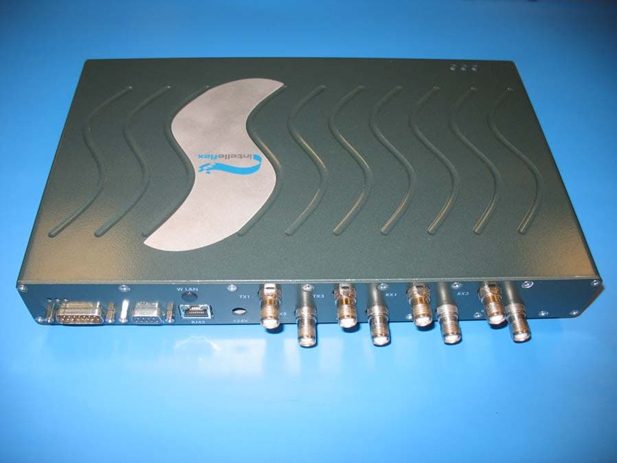
NTTSR320
Jun 20, 2006RFID Tag Reader
Equipment Class
DSS - Part 15 Spread Spectrum Transmitter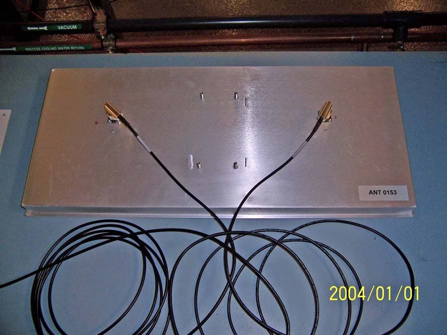
NTTWJSR22XX
Sep 12, 2005902-928MHz RFID Reader
Equipment Class
DSS - Part 15 Spread Spectrum Transmitter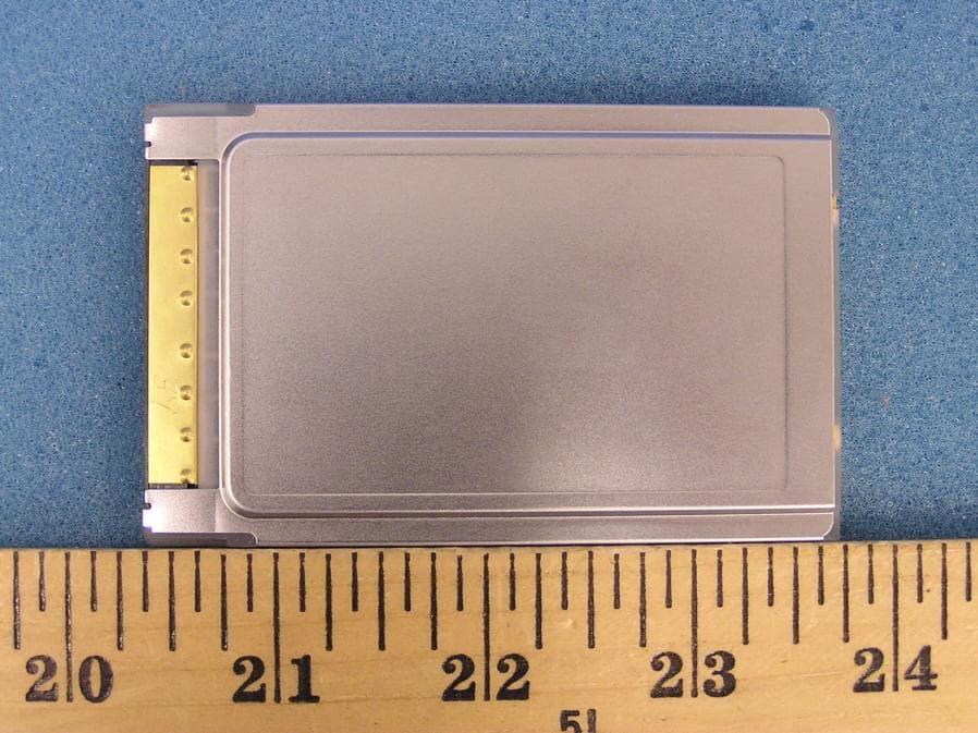
NTTWJMPR7XXX
Dec 12, 2004RFID Reader
Equipment Class
DSS - Part 15 Spread Spectrum Transmitter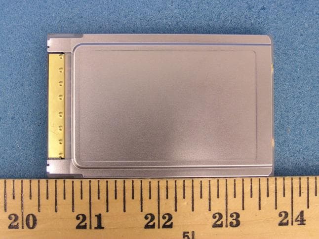
NTTWJMPR6XXX
Dec 09, 2004RFID Reader
Equipment Class
DSS - Part 15 Spread Spectrum Transmitter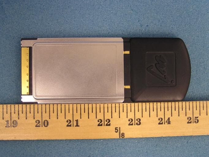
NTTWJMPR5XXX
Dec 09, 2004RFID Reader
Equipment Class
DSS - Part 15 Spread Spectrum Transmitter