NTTWJMPR5XXXRFID Reader
WJ Communications, Inc.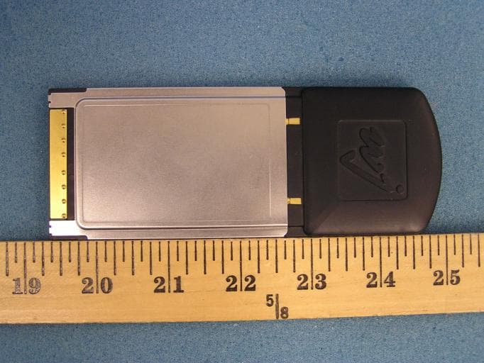
Click to zoom
Application Details
- Equipment Class
- DSS - Part 15 Spread Spectrum Transmitter
- Date of Grant
- Dec 09, 2004
- Application Purpose
- Original Equipment
- Date of Application
- Dec 09, 2004
- Equipment Note
- RFID Reader
- Frequency Range
- 903.00000000 - 927.00000000
- Company
- WJ Communications, Inc.
- Country
- United States
Documents & Files
Document Text
Text extracted from the exhibit documents filed with the FCC. Open a document above to read the original.
Users Manual
MPR series User’s Manual: Draftversion 0.95 11/4/04page 1 1 MPR Series MultiProtocol RFID Reader User’s Manual Version 0.95 11/4/04 1.1 Cover sheet MPR series User’s Manual: Draftversion 0.95 11/4/04page 2 1.2 TOC MPR series User’s Manual: Draftversion 0.95 11/4/04page 3 1.3 Introduction 1.3.1 Contents of this Document This manual describes installation and operation of the WJ Communications MPR5000, MPR6000, and MPR7000 PC-card-compatible UHF RFID readers. A description of the installation and use of the demonstration Graphical User Interface is also provided. The Application Programmer’s Interface to the MPR-series devices is described. 1.3.2 Audience This manual assumes that the reader is generally familiar with Windows personal computers and, if applicable, Windows CE or PocketPC handheld devices. An introduction to RFID technology is provided for readers who are new to the field. 1.3.3 RFID System Quickstart Radio Frequency Identification (RFID) uses electromagnetic waves to exchange information between a tag, containing (at least) a number uniquely identifying that physical tag and by implication the object to which it is attached, and a reader. RFID tags are analogous to bar codes, but can contain more information and are more versatile. The WJ Communications MPR-series readers are UHF readers, operating at a frequency of roughly 902- 928 MHz. These readers are compatible with EPCglobal Class 0 and EPCglobal Class 1 RFID tags, as well as class 0+ tags. They are not compatible with HF (13.56 MHz) tags generally used in Smart Cards, or LF (125/134 KHz) tags generally used in animal identification. MPR-series readers are configured as PC-card (PCMCIA)-slot-compatible modules, and require a host such as a laptop computer or handheld computer. With an appropriate host and if necessary an external antenna, an MPR-series reader can be used to acquire the unique identification number (UID) of one or more compatible tags in its reading range. When multiple tags are present in the field, collision resolution algorithms are applied to allow effectively simultaneous reading of all the readable tags. A more detailed discussion of RFID technology can be found in section 1.5. MPR series User’s Manual: Draftversion 0.95 11/4/04page 4 1.3.4 Product Description 1.3.4.1 MPR 5000 card with integral antenna The MPR5000 includes an antenna attached to the reader module, and is ready to be used as received. The antenna is not removable or replaceable. 1.3.4.2 MPR6000/7000 card with external antenna ports The MPR6000 and 7000 incorporate two MMCX-type adaptors for connecting up to two external antennas. The ports are interchangeable, and only one antenna may be used at any given time if desired. 1.3.4.2.1 Approved Antennas The MPR6000 and 7000 are approved for operation with either of two external antennas: a nearly-isotropic low-gain monopole antenna for general short-range use, and a higher-gain directional antenna when a specified coverage region is desired. MPR series User’s Manual: Draftversion 0.95 11/4/04page 5 Use of other than the approved antennas with this unit may result in harmful interference with other users, and cause the unit to fail to meet regulatory requirements. Professional installation is required for the MPR6000 and MPR7000 models. 1.3.4.2.1.1 Low gain, isotropic For general-purpose use where convenience is the main consideration, substantially isotropic operation is desired, and read range is unimportant, the MPR6000/7000 may be connected to a Maxrad Z1789 The Z1789 is shipped with an MMCX connector and may be attached directly to the card antenna ports, or a small-diameter extension cable, such as an RG-405 cable, may be used. Small-diameter cables that are mechanically appropriate for connection to an MMCX adaptor are generally relatively lossy and should not be used for lengths exceeding 2 meters (6 feet). 1.3.4.2.1.2 High gain, directional For applications where read range and control of the read zone are important, the MPR6000 may be connected to a Maxrad model MP9026CPRXFPT. This antenna is a right-hand-circularly polarized panel antenna, with a gain of 8.5 dBiC, front-to-back ratio of approximately 17 dB, and a 3 dB beamwidth of approximately 80°. The MPR7000 may be connected to a Maxrad model MP9027XFPTMSMA. This antenna is a right-hand- circularly polarized panel antenna, with a gain of 5.2 dBiC, front-to-back ratio of approximately 17 dB, and a 3 dB beamwidth of approximately 80°. The antenna is available with an N-female connector (-NF), or a male SMA connector (-MSMA). In either case, an adaptor may be required to connect the antenna to the MPR antenna port. Note that caution should be exercised in attaching any long, relatively heavy cables to the MPR MMCX adaptors, as these adaptors are not intended to tolerate large mechanical stresses. WJ Communications recommends that the MPR output port be connected through a short length of small-diameter cabling, such as RG-405, with stress relief to protect the card adaptor in the event of displacement of the cabling, and then an adaptor should be used to mate this intermediate cable to the antenna cabling. 1.3.4.3 CD with this manual, drivers, and demo software 1.4 Installation and Operation with demonstration Graphical User Interface 1.4.1 Introduction This chapter describes how to install the the WJ MPR series Multi-Protocol RFID PC Card Demo Software for Microsoft Windows, Windows CE, and PocketPC operating systems. These instructions are written for Microsoft XP operating system. For other MS Windows operating systems the details of some instructions may be slightly different, but by following the onscreen instructions the installation will proceed similarly. Windows 95 and Windows NT operating systems are not currently supported. The PC and Pocket PC demos were written using the .NET Framework and Compact Framework respectively. Thus, the MS .NET Common Runtime must be installed for these programs (and their installers)…
Text truncated - open the document above for the full version.
Cover Letter(s)
tel: 650-726-1263 fax: 650-726-1252 [email protected] Thomas N. CokeniasEMC &Radio Approvals Test & Consulting Services for Commercial, Military, International Compliance P.O. Box 1086 El Granada, CA 94018 Compliance Certification Services4 December 2004 561 F Monterey Road Morgan Hill CA 95037 Attention: Mike Kuo Reviewing Engineer Applicant: WJ Communications Inc. FCC ID: (a) NTTWJMPR5XXX (b) NTTWJMPR6XXX (c) NTTWJMPR7XXX Dear Mike, Request is hereby submitted, per section 0.459 of the Rules, on behalf of my client WJ Communications Inc., to withhold from public review certain portions of the application for equipment certification for the referenced FCC identifier. In particular, the following sections of the application and report are requested to be kept confidential: Block Diagrams Schematic Operational Description Rationale for request for confidentiality: WJ has invested considerable time and materials in research and development to produce the referenced product. Disclosure of the confidential portions of this application to competitors would give them competitive advantage in developing similar products. If you have questions or need further information, please contact the undersigned. Sincerely, THOMAS N. COKENIAS EMC Consultant/Agent for WJ Communications Inc.
Cover Letter(s)
1 Chris Harvey From:Tom Cokenias [[email protected]] Sent:Thursday, December 09, 2004 8:22 PM To:Chris Harvey Subject:RE: looking for information for WJ Assessment # AN04T4383 Hi Chris, I'll upload the letter(s) this evening. Re tags: the received signal is at the same frequency as the reader TX signal. best regards Tom >Tom a couple more quick questions: > >1) I see you want Confidentiality, but you did not upload a >Confidentiality Letter. Please update this or change the Form 731. > >2) Please indicate the Return Frequency (back-scatter) from the tags >and indicate if this is contained in a restricted band frequency of FCC >15.205. > >Thanks, > >Chris > >Chris Harvey >Chris Harvey EMC Consultants, LLC >[email protected] >cell 443-622-3300 > > >-----Original Message----- >From: Tom Cokenias [mailto:[email protected]] >Sent: Thursday, December 09, 2004 11:21 AM >To: [email protected] >Subject: Re: looking for information for WJ Assessment # AN04T4383 > >Hi Chris, > >I uploaded the SAR report attachments to both FCC and IC filings on the >website. > >best regards > >Tom > >>Tom, I don't have full computer access right now but I have noticed >>that the SAR plots, validation info, probe and dipole calibrations are >>also missing. >> >>Please submit these items. 2 >> >> >>-----Original Message----- >>From: Tom Cokenias <[email protected]> >>Date: Wed, 8 Dec 2004 15:31:12 >>To:[email protected] >>Subject: Re: looking for information for WJ Assessment # AN04T4383 >> >>Hi Chris, >> >>I will be uploading operational and FHSS operational description to >>the TCB FCC and ID websites but in case they don't take, I've attached >>them here. Same for all 3 IDs. >> >>best regards >> >>Tom >> >> >> >>>Tom, I do not see a file called operation-anything for all 3 apps. >>>Yes an operational description directed to the FHSS requirements >>>would be very helpful. -----Original Message----- >>>From: Tom Cokenias <[email protected]> >>>Date: Wed, 8 Dec 2004 10:18:14 >>>To:"Chris Harvey" <[email protected]> >>>Subject: Re: looking for information for WJ Assessment # AN04T4383 >>> >>>Hi Chris, >>> >>> >>>Thanks for getting to this so quickly. The reason you can't find >>>the label location photo is it wasn't there. I have uploaded same >>>for all the FCC IDs and will do the same for the IC applications in a >>>few minutes. >>> >>> >>>All three FCC application upload record show a pdf file named >>>operational.pdf as being uploaded, this is the operational >>>description. >>> >>> >>>It calls out 50 channels and random hopping, but if it would help you >>>client and I can write a supplemental operational description >>>directed to the provisions of the FHHS system. Let me know if this >>>would be helpful... >>> >>> >>>best regards >>> >>> >>> >>> >>>Tom >>> >>> >>> >>> Tom due to the urgency of this application I may be asking these >>>questions before digging deep enough, but I can1t seem to find the 3 >>>following: >>> >>> 1) compliance with all provisions for FHSS systems, for exampleS >>> >>> 15.247(a)(1) The system shall hop to channel frequencies that are >>>selected at the system hopping rate from a >>> pseudorandomly ordered list of hopping frequencies. Each >>>frequency must be used equally on the >>> average by each transmitter. The system receivers shall have >>>input bandwidths that match the hopping >>> channel bandwidths of their corresponding transmitters and shall >>>shift frequencies in synchronization with >>> the transmitted signals. >>> >>> 15.247 (g) Frequency hopping spread spectrum systems are not >>>required to employ all available hopping >>> channels during each transmission. However, the system, >>>consisting of both the transmitter and the >>> receiver, must be designed to comply with all of the regulations >>>in this section should the transmitter be >>> presented with a continuous data (or information) stream. In >>>addition, a system employing short >>> transmission bursts must comply with the definition of a >>>frequency hopping system and must distribute its >>> transmissions over the minimum number of hopping channels >>>specified in this section. >>> >>> 15.247(h) The incorporation of intelligence within a frequency > >>hopping spread spectrum system that >>> permits the system to recognize other users within the spectrum >>>band so that it individually and >>> independently chooses and adapts its hopsets to avoid hopping on >>>occupied channels is permitted. The >>> coordination of frequency hopping systems in any other manner for >>>the express purpose of avoiding the >>> simultaneous occupancy of individual hopping frequencies by >>>multiple transmitters is not permitted. >>> >>> I can not find a label location diagram/photo (I know it is >>>obvious, but it must be in the application). >>> >>> I can not find a detailed operational/technical description for >>>this device (which might answer some of the questions above). >>> >>> It is likely that these same items will be needed for the other 2 >>>WJ applications. Please look into those and provide the information >>>as needed. >>> >>> Thanks, >>> >>> Chris Harvey >> > Chris Harvey EMC Consultants, LLC >>> [email protected] >>> cell 443-622-3300 >>> >>> >>> >>>Best Regards, >>> 4 >>>Chris Harvey >>>[email protected] >> >> >>Best Regards, >> >>Chris Harvey >>[email protected]
External Photos
WJ Communications Inc. FCC ID: NTTWJMPR5XXX 0.5 Watt RFID Reader External Photographs
ID Label/Location Info
WJ RFI D Reader FCC ID Labels FCC ID: NTTWJMPR5XXX IC: 3374A-MPR5XXX This device complies with Part 15 of the FCC Rules. Operation is subject to the following two conditions: (1) this device may not cause harmful interference, and (2) this device must accept any interference received, including interference that may cause undesired operation. FCC ID: NTTWJMPR6XXX IC: 3374A-MPR6XXX This device complies with Part 15 of the FCC Rules. Operation is subject to the following two conditions: (1) this device may not cause harmful interference, and (2) this device must accept any interference received, including interference that may cause undesired operation. FCC ID: NTTWJMPR7XXX IC: 3374A-MPR7XXX This device complies with Part 15 of the FCC Rules. Operation is subject to the following two conditions: (1) this device may not cause harmful interference, and (2) this device must accept any interference received, including interference that may cause undesired operation
ID Label/Location Info
FCC ID: NTTWJMPR5XXX Label Location Area FCC IDs: NTTWJMPR6XXX, NTTWJMPR7XXX
Internal Photos
WJ Communications Inc. FCC ID: NTTWJMPR5XXX 0.5 Watt RFID Reader Internal Photographs
RF Exposure Info
IN ACCORDANCE WITH THE REQUIREMENTS OF FCC REPORT AND ORDER: ET DOCKET 93-62, AND OET BULLETIN 65 SUPPLEMENT C FOR PCMCIA RFID Reader Card MODEL: MPR5000 FCC ID: NTTWJMPR5XXX REPORT NUMBER: 04U2954-4 ISSUE DATE: November 24, 2004 Prepared for WJ Communications 401 River Oaks Parkway San Jose, CA 95134, USA Prepared by COMPLIANCE CERTIFICATION SERVICES 561F MONTEREY ROAD, MORGAN HILL, CA 95037, USA TEL: (408) 463-0885 REPORT NO: 04U2954-4 DATE: November 24, 2004 FCC ID: NTTWJMPR5XXX Revision History Rev. Revisions Revised By COMPLIANCE CERTIFICATION SERVICES Page: 2 of 31 This report shall not be reproduced except in full, without the written approval of CCS. REPORT NO: 04U2954-4 DATE: November 24, 2004 FCC ID: NTTWJMPR5XXX CERTIFICATE OF COMPLIANCE (SAR EVALUATION) DATES OF TEST: November 15 - 16, 2004 APPLICANT: WJ Communications ADDRESS: 401 River Oaks Parkway San Jose, CA 95134, USA FCC ID: NTTWJMPR5XXX MODEL: MPR5000 DEVICE CATEGORY: Portable Device EXPOSURE CATEGORY: General Population/Uncontrolled Explosure PCMCIA RFID Reader Card Test Sample is a: Production unit Modulation type: DBPSK FCC Rule Parts Frequency Range [MHz] The Highest SAR Values [1g_mW/g] Max. Power Output [dBm] 47 CFR 15.247 902 - 928 1.48 26.77 This wireless portable device has been shown to be capable of compliance for localized specific absorption rate (SAR) for General Population/Uncontrolled Explosure limits specified in ANSI/IEEE Std. C95.1-1992 and had been tested in accordance with the measurement procedures specified in FCC OET 65 Supplement C (Edition 01-01). Note: The results documented in this report apply only to the tested sample, under the conditions and modes of operation as described herein. This document may not be altered or revised in any way unless done so by Compliance Certification Services and all revisions are duly noted in the revisions section. Any alteration of this document not carried out by Compliance Certification Services will constitute fraud and shall nullify the document. No part of this report may be used to claim product certification, approval, or endorsement by NVLAP, NIST, or any government agency. Released For CCS By: Hsin-Fu Shih (Sunny Shih) COMPLIANCE CERTIFICATION SERVICES COMPLIANCE CERTIFICATION SERVICES Page: 3 of 31 This report shall not be reproduced except in full, without the written approval of CCS. REPORT NO: 04U2954-4 DATE: November 24, 2004 FCC ID: NTTWJMPR5XXX TABLE OF CONTENTS 1 EQUIPMENT UNDER TEST (EUT) DESCRIPTION............................................................................5 2 FACILITIES AND ACCREDITATION................................................................................................... 5 3 SYSTEM DESCRIPTION.....................................................................................................................6 4 SYSTEM COMPONENTS....................................................................................................................7 4.1 DASY4 MEASUREMENT SERVER.............................................................................................. 7 4.2 DATA ACQUISITION ELECTRONICS (DAE)...............................................................................7 4.3 EX3DV3 ISOTROPIC E-FIELD PROBE FOR DOSIMETRIC MEASUREMENTS.......................7 4.4 LIGHT BEAM UNIT.......................................................................................................................8 4.5 SAM PHANTOM (V4.0).................................................................................................................8 4.6 DEVICE HOLDER FOR SAM TWIN PHANTOM..........................................................................9 4.7 SYSTEM VALIDATION KITS........................................................................................................ 9 4.8 COMPOSITION OF INGREDIENTS FOR TISSUE SIMULATING LIQUID..................................9 5 TEST POSITIONS FOR DEVICES OPERATING NEXT TO A PERSON’S EAR..............................10 5.1 CHEEK/TOUCH POSITION........................................................................................................ 11 5.2 EAR/TILT POSITION..................................................................................................................12 6 TEST POSITIONS FOR BODY-WORN AND OTHER SIMILAR CONFIGURATIONS.....................13 7 SIMULATING LIQUID PARAMETERS CHECK.................................................................................14 7.1 SIMULATING LIQUID PARAMETER CHECK RESULT.............................................................15 8 SYSTEM PERFORMANCE CHECK..................................................................................................17 8.1 SYSTEM PERFORMANCE CHECK RESULTS.........................................................................18 9 SAR MEASUREMENT PROCEDURES............................................................................................. 19 10 PROCEDURES USED TO ESTABLISH TEST SIGNAL....................................................................21 11 SAR MEASUREMENT RESULTS.....................................................................................................22 11.1 LAPHELD POSITION (HOST # 1 – SONY, MODEL PCG-Z505HE)..........................................22 11.2 LAPHELD POSITION (HOST # 2 – DELL, MODEL PP08L)......................................................23 11.3 LAPHELD POSITION (HOST # 3 – SONY, MODEL PCG-651R)..............................................24 12 EUT PHOTOS....................................................................................................................................25 13 MEASUREMENT UNCERTAINTY.....................................................................................................29 14 EQUIPMENT LIST & CALIBRATION................................................................................................. 30 15 ATTACHMENTS..............................................…
Text truncated - open the document above for the full version.
RF Exposure Info
Date/Time: 11/24/04 08:45:13 Test Laboratory: Compliance Certification Services System Performance Check @ 900MHz DUT: Dipole 900 MHz; Type: D900V2; Serial: 108 Phantom section: Flat Section Frequency: 900 MHz;Duty Cycle: 1:1 Medium parameters used: f = 900 MHz; σ = 0.996 mho/m; ε r = 41.9; ρ = 1000 kg/m 3 Measurement Standard: DASY4 (High Precision Assessment) z Room Ambient Temperature: 23.0 deg. C; Liquid Temperature: 22.5 deg. C z Area Scan setting - Find Secondary Maximum Within: 2.0 dB and with a peak SAR value greater than 0.0012W/kg z Probe: EX3DV3 - SN3531; ConvF(10.2, 10.2, 10.2); z Sensor-Surface: 2.5mm (Mechanical Surface Detection) z Electronics: DAE3 Sn500; Calibrated: 12/23/2003 z Phantom: SAM 1; Type: SAM 1; Serial: 1185 z Measurement SW: DASY4, V4.4 Build 3; Postprocessing SW: SEMCAD, V1.8 Build 130 d=15mm, Pin=250mW/Area Scan (7x9x1): Measurement grid: dx=15mm, dy=15mm Maximum value of SAR (measured) = 3.54 mW/g d=15mm, Pin=250mW/Zoom Scan (5x5x7)/Cube 0: Measurement grid: dx=7.5mm, dy=7.5mm, dz=5mm Reference Value = 59.8 V/m; Power Drift = 0.0 dB Peak SAR (extrapolated) = 4.37 W/kg SAR(1 g) = 2.85 mW/g; SAR(10 g) = 1.82 mW/g Maximum value of SAR (measured) = 3.51 mW/g 0 dB = 3.51mW/g Date/Time: 11/24/04 08:45:13 Test Laboratory: Compliance Certification Services System Performance Check @ 900MHz DUT: Dipole 900 MHz; Type: D900V2; Serial: 108 Phantom section: Flat Section Measurement Standard: DASY4 (High Precision Assessment) d=15mm, Pin=250mW/Z Scan (1x1x41): Measurement grid: dx=20mm, dy=20mm, dz=2.5mm Maximum value of SAR (measured) = 4.77 mW/g
RF Exposure Info
Date/Time: 11/24/04 14:56:16 Test Laboratory: Compliance Certification Services Host # 1 DUT: WJ Communicatrions; Type: MPR50xx; Serial: n/a Phantom section: Flat Section Frequency: 902.75 MHz;Duty Cycle: 1:2.13 Medium parameters used (interpolated): f = 902.75 MHz; σ = 1.09 mho/m; ε r = 54.6; ρ = 1000 kg/m 3 Measurement Standard: DASY4 (High Precision Assessment) z Room Ambient Temperature: 23.0 deg. C; Liquid Temperature: 22.5 deg. C z Area Scan setting - Find Secondary Maximum Within: 2.0 dB and with a peak SAR value greater than 0.0012W/kg z Probe: EX3DV3 - SN3531; ConvF(10.1, 10.1, 10.1); z Sensor-Surface: 2.5mm (Mechanical Surface Detection) z Electronics: DAE3 Sn500; Calibrated: 12/23/2003 z Phantom: SAM 2; Type: SAM 2; Serial: 1050 z Measurement SW: DASY4, V4.4 Build 3; Postprocessing SW: SEMCAD, V1.8 Build 130 L-ch/Area Scan (11x9x1): Measurement grid: dx=15mm, dy=15mm Info: Interpolated medium parameters used for SAR evaluation! Maximum value of SAR (measured) = 1.79 mW/g L-ch/Zoom Scan (5x5x7)/Cube 0: Measurement grid: dx=7.5mm, dy=7.5mm, dz=5mm Reference Value = 14.9 V/m; Power Drift = 0.2 dB Peak SAR (extrapolated) = 2.34 W/kg SAR(1 g) = 1.45 mW/g; SAR(10 g) = 0.904 mW/g Info: Interpolated medium parameters used for SAR evaluation! Maximum value of SAR (measured) = 1.83 mW/g 0 dB = 1.83mW/g Date/Time: 11/24/04 14:56:16 Test Laboratory: Compliance Certification Services Host # 1 DUT: WJ Communicatrions; Type: MPR50xx; Serial: n/a Phantom section: Flat Section Measurement Standard: DASY4 (High Precision Assessment) L-ch/Z Scan (1x1x41): Measurement grid: dx=20mm, dy=20mm, dz=2.5mm Info: Interpolated medium parameters used for SAR evaluation! Maximum value of SAR (measured) = 1.75 mW/g Date/Time: 11/24/04 14:56:16 Test Laboratory: Compliance Certification Services Host # 1 DUT: WJ Communicatrions; Type: MPR50xx; Serial: n/a Phantom section: Flat Section Frequency: 914.75 MHz;Duty Cycle: 1:2.13 Medium parameters used (interpolated): f = 914.75 MHz; σ = 1.09 mho/m; ε r = 54.5; ρ = 1000 kg/m 3 Measurement Standard: DASY4 (High Precision Assessment) z Room Ambient Temperature: 23.0 deg. C; Liquid Temperature: 22.5 deg. C z Area Scan setting - Find Secondary Maximum Within: 2.0 dB and with a peak SAR value greater than 0.0012W/kg z Probe: EX3DV3 - SN3531; ConvF(10.1, 10.1, 10.1); z Sensor-Surface: 2.5mm (Mechanical Surface Detection) z Electronics: DAE3 Sn500; Calibrated: 12/23/2003 z Phantom: SAM 2; Type: SAM 2; Serial: 1050 z Measurement SW: DASY4, V4.4 Build 3; Postprocessing SW: SEMCAD, V1.8 Build 130 M-ch/Area Scan (11x9x1): Measurement grid: dx=15mm, dy=15mm Info: Interpolated medium parameters used for SAR evaluation! Maximum value of SAR (measured) = 1.32 mW/g M-ch/Zoom Scan (5x5x7)/Cube 0: Measurement grid: dx=7.5mm, dy=7.5mm, dz=5mm Reference Value = 14.3 V/m; Power Drift = -0.2 dB Peak SAR (extrapolated) = 1.63 W/kg SAR(1 g) = 1.01 mW/g; SAR(10 g) = 0.634 mW/g Info: Interpolated medium parameters used for SAR evaluation! Maximum value of SAR (measured) = 1.21 mW/g 0 dB = 1.21mW/g Date/Time: 11/24/04 14:56:16 Test Laboratory: Compliance Certification Services Host # 1 DUT: WJ Communicatrions; Type: MPR50xx; Serial: n/a Phantom section: Flat Section Frequency: 927.25 MHz;Duty Cycle: 1:2.13 Medium parameters used (interpolated): f = 927.25 MHz; σ = 1.11 mho/m; ε r = 54.4; ρ = 1000 kg/m 3 Measurement Standard: DASY4 (High Precision Assessment) z Room Ambient Temperature: 23.0 deg. C; Liquid Temperature: 22.5 deg. C z Area Scan setting - Find Secondary Maximum Within: 2.0 dB and with a peak SAR value greater than 0.0012W/kg z Probe: EX3DV3 - SN3531; ConvF(10.1, 10.1, 10.1); z Sensor-Surface: 2.5mm (Mechanical Surface Detection) z Electronics: DAE3 Sn500; Calibrated: 12/23/2003 z Phantom: SAM 2; Type: SAM 2; Serial: 1050 z Measurement SW: DASY4, V4.4 Build 3; Postprocessing SW: SEMCAD, V1.8 Build 130 H-ch/Area Scan (11x9x1): Measurement grid: dx=15mm, dy=15mm Info: Interpolated medium parameters used for SAR evaluation! Maximum value of SAR (measured) = 0.933 mW/g H-ch/Zoom Scan (5x5x7)/Cube 0: Measurement grid: dx=7.5mm, dy=7.5mm, dz=5mm Reference Value = 11.5 V/m; Power Drift = -0.1 dB Peak SAR (extrapolated) = 1.21 W/kg SAR(1 g) = 0.732 mW/g; SAR(10 g) = 0.463 mW/g Info: Interpolated medium parameters used for SAR evaluation! Maximum value of SAR (measured) = 0.947 mW/g H-ch/Zoom Scan (5x5x7)/Cube 1: Measurement grid: dx=7.5mm, dy=7.5mm, dz=5mm Reference Value = 11.5 V/m; Power Drift = -0.1 dB Peak SAR (extrapolated) = 1.09 W/kg SAR(1 g) = 0.672 mW/g; SAR(10 g) = 0.439 mW/g Info: Interpolated medium parameters used for SAR evaluation! Maximum value of SAR (measured) = 0.866 mW/g Date/Time: 11/24/04 12:09:54 Test Laboratory: Compliance Certification Services Host # 2 DUT: WJ Communicatrions; Type: MPR50xx; Serial: n/a Phantom section: Flat Section Frequency: 902.75 MHz;Duty Cycle: 1:2.13 Medium parameters used (interpolated): f = 902.75 MHz; σ = 1.09 mho/m; ε r = 54.6; ρ = 1000 kg/m 3 Measurement Standard: DASY4 (High Precision Assessment) z Room Ambient Temperature: 23.0 deg. C; Liquid Temperature: 22.5 deg. C z Area Scan setting - Find Secondary Maximum Within: 2.0 dB and with a peak SAR value greater than 0.0012W/kg z Probe: EX3DV3 - SN3531; ConvF(10.1, 10.1, 10.1); z Sensor-Surface: 2.5mm (Mechanical Surface Detection) z Electronics: DAE3 Sn500; Calibrated: 12/23/2003 z Phantom: SAM 2; Type: SAM 2; Serial: 1050 z Measurement SW: DASY4, V4.4 Build 3; Postprocessing SW: SEMCAD, V1.8 Build 130 L-ch/Area Scan (11x9x1): Measurement grid: dx=15mm, dy=15mm Info: Interpolated medium parameters used for SAR evaluation! Maximum value of SAR (measured) = 1.33 mW/g L-ch/Zoom Scan (5x5x7)/Cube 0: Measurement grid: dx=7.5mm, dy=7.5mm, dz=5mm Reference Value = 9.99 V/m; Power Drift = -0.14 dB Peak SAR (extrapolated) = 1.99 W/kg SAR(1 g) = 1.13 mW/g; SAR(10 g) = 0.662 mW/g Info: Interpolated medium parameters used for SAR evaluation! Maximum value of SAR (measured) = 1.5 mW/g 0 dB = 1.5m…
Text truncated - open the document above for the full version.
Test Report
FCC CFR47 PART 15 SUBPART C CERTIFICATION TEST REPORT FOR PCMCIA RFID READER CARD MODEL NUMBER: MPR5000 FCC ID: NTTWJMPR5XXX REPORT NUMBER: 04U2954-5 ISSUE DATE: NOVEMBER 12, 2004 Prepared for WJ COMUNICATIONS 401 RIVER OAKS PARKWAY SAN JOSE, CA 95134 Prepared by COMPLIANCE CERTIFICATION SERVICES 561F MONTEREY ROAD, MORGAN HILL, CA 95037, USA TEL: (408) 463-0885 FAX: (408) 463-0888 REPORT NO: 04U2954-5 DATE: NOVEMBER 22, 2004 EUT: HALF WATT PCMCIA RFID READER CARD: MPR5000 FCC ID: NTTWJMP5XXX Page 2 of 85 COMPLIANCE CERTIFICATION SERVICES DOCUMENT NO: CCSUP4031A 561F MONTEREY ROAD, MORGAN HILL, CA 95037 USA TEL: (408) 463-0885 FAX: (408) 463-0888 This report shall not be reproduced except in full, without the written approval of CCS. Revision History Rev. Revisions Revised By REPORT NO: 04U2954-5 DATE: NOVEMBER 22, 2004 EUT: HALF WATT PCMCIA RFID READER CARD: MPR5000 FCC ID: NTTWJMP5XXX Page 3 of 85 COMPLIANCE CERTIFICATION SERVICES DOCUMENT NO: CCSUP4031A 561F MONTEREY ROAD, MORGAN HILL, CA 95037 USA TEL: (408) 463-0885 FAX: (408) 463-0888 This report shall not be reproduced except in full, without the written approval of CCS. TABLE OF CONTENTS 1. ATTESTATION OF TEST RESULTS............................................................................................. 5 2. TEST METHODOLOGY.................................................................................................................. 6 3. FACILITIES AND ACCREDITATION.......................................................................................... 6 4. CALIBRATION AND UNCERTAINTY.......................................................................................... 6 4.1. MEASURING INSTRUMENT CALIBRATION............................................................................. 6 4.2. MEASUREMENT UNCERTAINTY............................................................................................... 6 5. EQUIPMENT UNDER TEST............................................................................................................7 5.1. DESCRIPTION OF EUT..............................................................................................................7 5.2. MAXIMUM OUTPUT POWER.................................................................................................... 7 5.3. DESCRIPTION OF AVAILABLE ANTENNAS............................................................................. 7 5.4. SOFTWARE AND FIRMWARE..................................................................................................…
Text truncated - open the document above for the full version.
Contact Information
Applicant
Tim Buchner(Strategic Marketing)
Test Firm
Compliance Certification Services IncSteve Cheng
Technical Specifications
| # | Rule Parts | Frequency Range | Power Output |
|---|---|---|---|
| 1 | 15C | 903 MHz - 927 MHz | 475.00 mW |
Other Applications from WJ Communications, Inc.
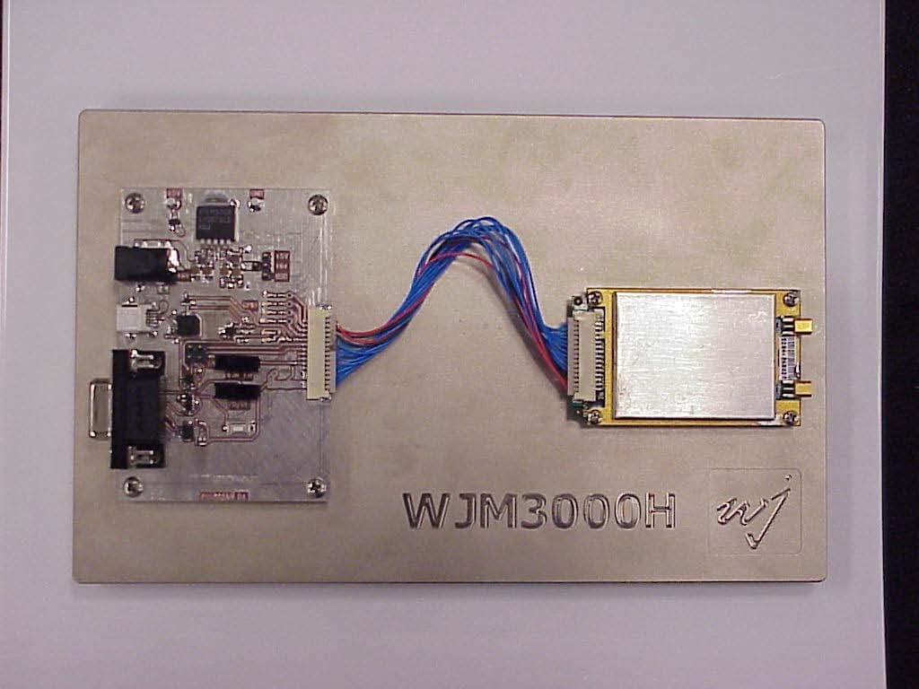
NTTWJM3000
Jan 11, 2007RFID Reader Module
Equipment Class
DSS - Part 15 Spread Spectrum Transmitter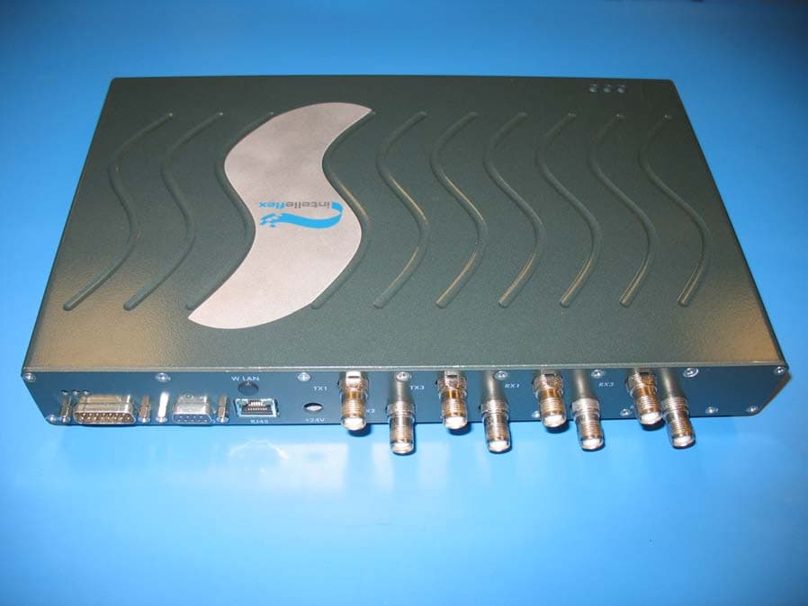
NTTSR320
Jun 20, 2006RFID Tag Reader
Equipment Class
DSS - Part 15 Spread Spectrum Transmitter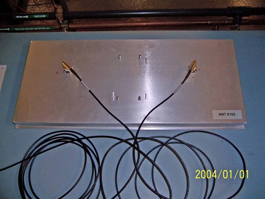
NTTWJSR22XX
Sep 12, 2005902-928MHz RFID Reader
Equipment Class
DSS - Part 15 Spread Spectrum Transmitter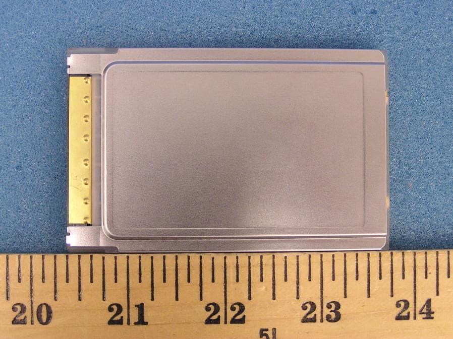
NTTWJMPR7XXX
Dec 12, 2004RFID Reader
Equipment Class
DSS - Part 15 Spread Spectrum Transmitter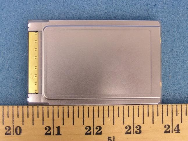
NTTWJMPR6XXX
Dec 09, 2004RFID Reader
Equipment Class
DSS - Part 15 Spread Spectrum Transmitter