NTTSX1121Customer Premises MMDS
WJ Communications, Inc.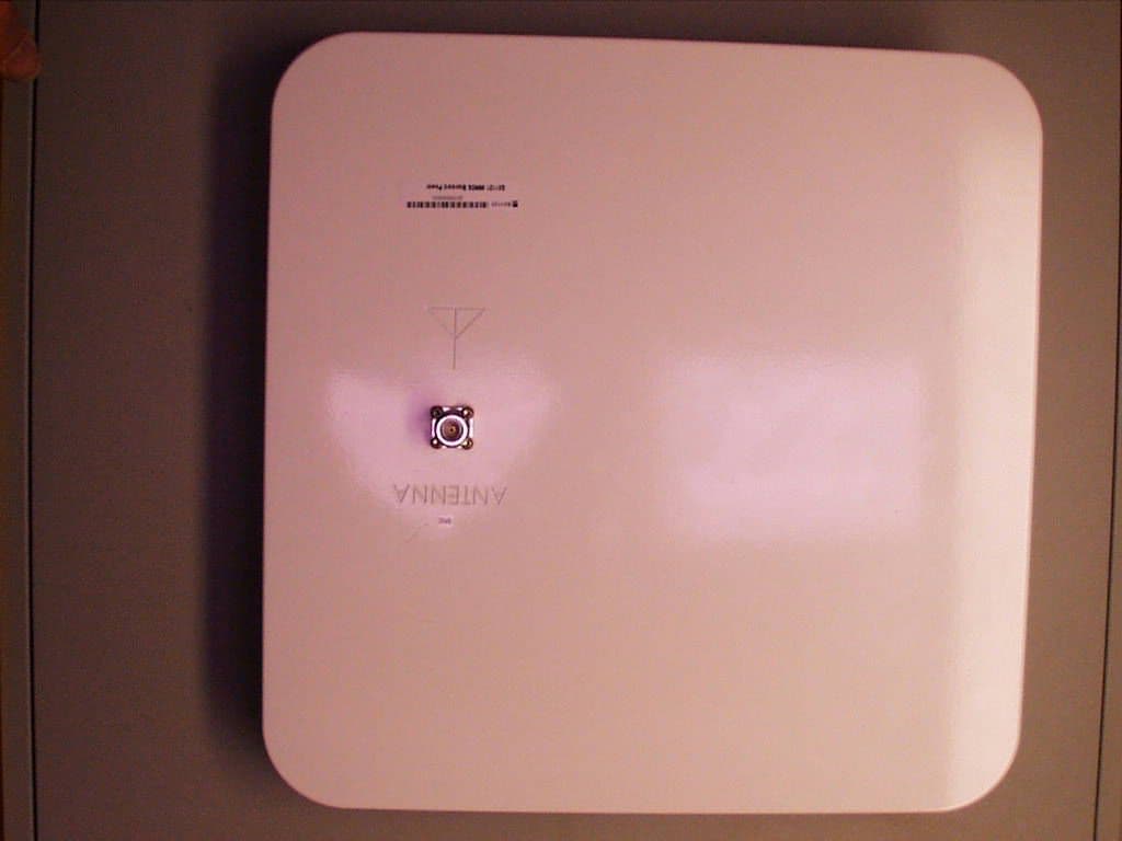
Click to zoom
Application Details
- Equipment Class
- TNB - Licensed Non-Broadcast Station Transmitter
- Date of Grant
- Jul 30, 2000
- Application Purpose
- Original Equipment
- Date of Application
- Jan 28, 2000
- Equipment Note
- Customer Premises MMDS
- Frequency Range
- 2500.00000000 - 2686.00000000
- Company
- WJ Communications, Inc.
- Country
- United States
Documents & Files
Document Text
Text extracted from the exhibit documents filed with the FCC. Open a document above to read the original.
Users Manual
Regulatory Compliance and Safety Information This section provides international agency compliance, safety, and statutory information regarding the removal and replacement of the WJ broadband fixed wireless system transceiver. FCC Compliance Information The following paragraphs describe requirements and information based on FCC rules. This WJ product has been tested and complies with the requirements in Part 2 and Part 21 of FCC Rules for a transmitter of this type. Ths product also complies with the class B emissions limits in Part 15 for digital circuitry emissions, when installed with shielded cables.
Cover Letter(s)
Watkins Johnson.FCC ID: NTTSX1122 1 Thomas N. Cokenias EMC &Radio Approvals Test & Consulting Services for Commercial, Military, International Compliance P.O. Box 1086 El Granada, CA 94018 20 January 2000 FCC Laboratory 7435 Oakland Mills Road Columbia, MD 21046 Attention: Application Examiner Reviewing Engineer Re: Request for confidentiality per Section 0.459 of FCC Rules Applicant: Watkins Johnson. FCC ID: NTTSX1121 To whom it may concern, Request is hereby submitted, on behalf of my client Watkins Johnson, to withhold from public review certain portions of the application for equipment certification for the referenced FCC identifier. In particular, the following sections of the application and report are requested to be kept confidential: Schematics Block diagrams Theory of operation (P2P Architecture) Rationale for request for confidentiality: Watkins Johnson has invested considerable time and materials in research and development to produce the referenced product. Disclosure of the confidential portions of this application to competitors would give them competitive advantage in developing similar products. The $135 fee for confidentiality has been submitted along with the fee for certification. If you have questions or need further information, please contact the undersigned. Sincerely, THOMAS N. COKENIAS EMC Consultant/Agent for Watkins Johnson. Watkins Johnson.FCC ID: NTTSX1122 2 Tel 650 726 1263 fax 650 726 [email protected]
Cover Letter(s)
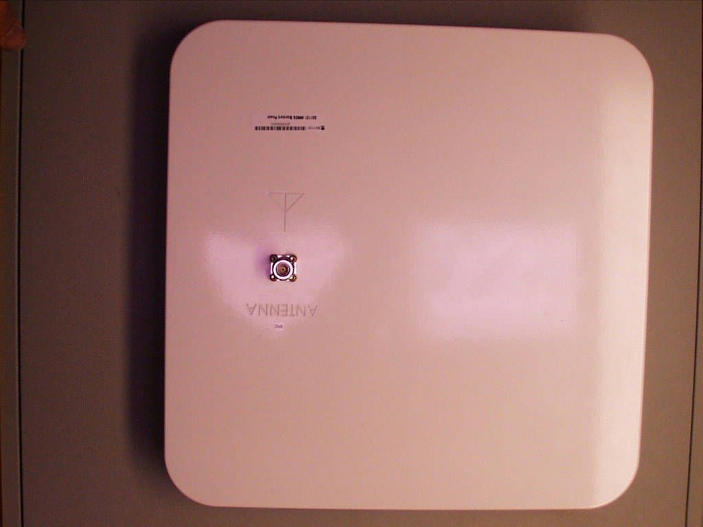
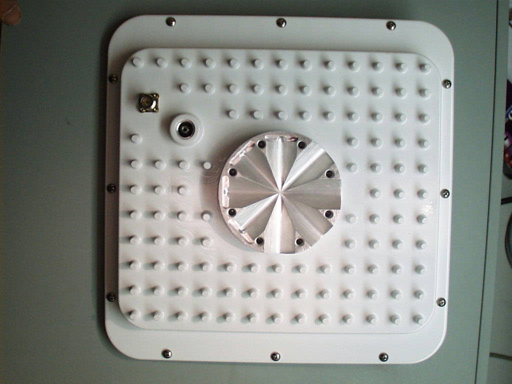
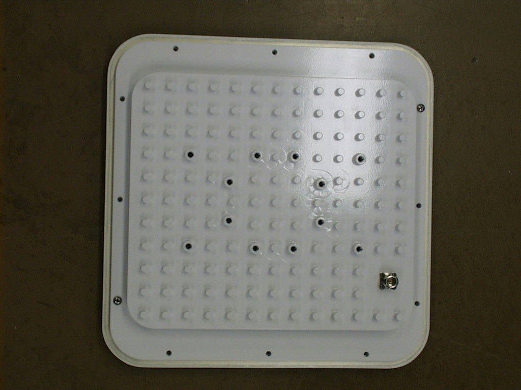
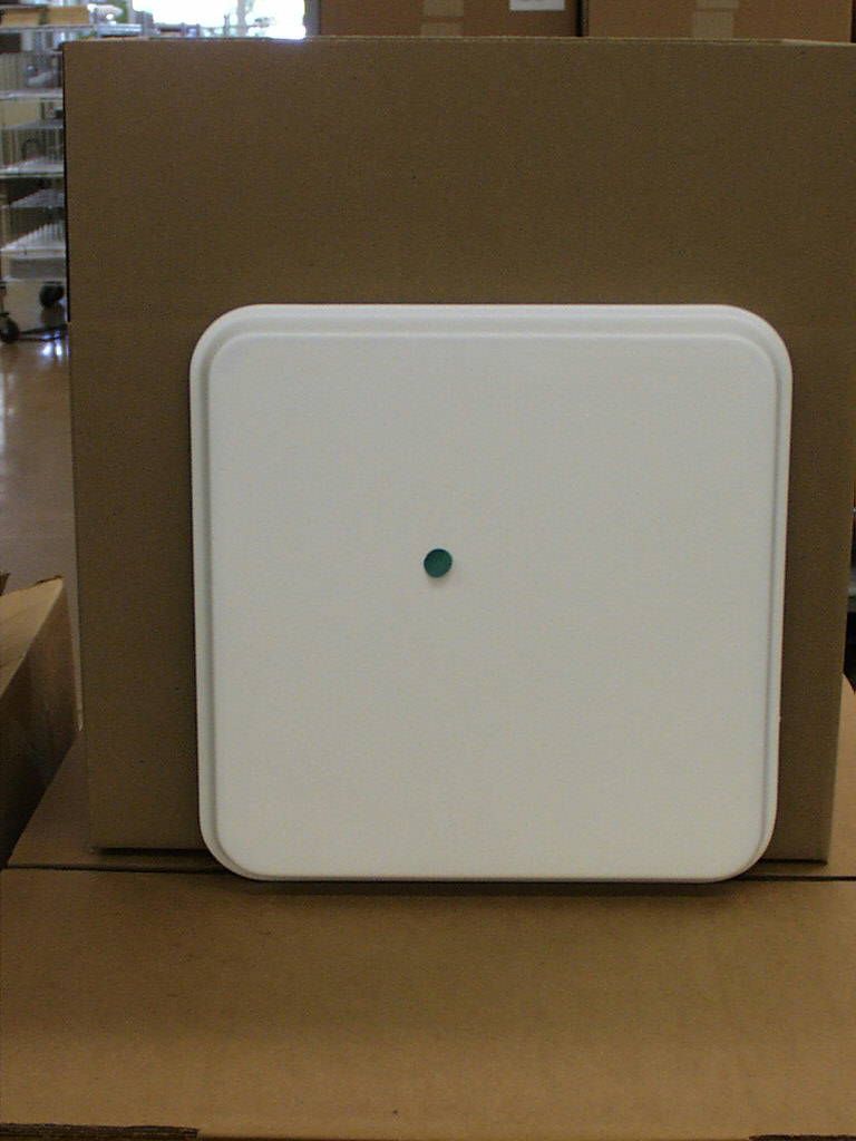
tel: 650-726-1263 fax: 650-726-1252 internet: [email protected] Thomas N. Cokenias EMC & Radio Type Approvals Test & Consulting Services for Commercial, Military, International Compliance P.O. Box 1086 El Granada, CA 94018 5 May 2000 FCC Laboratory 7435 Oakland Mills Road Columbia, MD 21046 Attention: Frank Coperich Re: Variant for Watkins-Johnson MMDS Radi0 FCC ID: NTTSX1121 Dear Frank, The radio currently submitted for certification will have a variation. This variation will be the inclusion of an integral antenna, in addition to the case with the connector for an external antenna. The boards, power supplies, parts, circuit layouts are identical. Only mechanical changes have been incorporated to make possible the integration of a flat panel antenna. Photographs have been submitted to the website. Data taken on the external antenna unit is representative of and applicable to emissions characteristics of the integral antenna unit. If you have questions or need further information, please don’t hesitate to call. Sincerely, T.N. Cokenias EMC Consultant/Agent for Watkins-Johnson
ID Label/Location Info
FCC ID Label and Label Location for Watkins-Johnson FCC ID: NTTSX1121 Watkins-Johnson SX1121 FCC ID: NTTSX1121 This device complies with Part 15 of the FCC Rules. Operation is subject to the following two conditions: (1) This device may not cause harmful interference, and (2) This device must accept any interference received, including interference than may cause undesired operation
RF Exposure Info
FCC Warning label for CPE Equipment CAUTION: To comply with FCC RF exposure requirements, antennas used for this device must be installed to provide a separation distance of at least 90 cm to satisfy RF exposure compliance Label size: Approx. 7 cm x 1.5 cm, 14 point type. Label to be place on side of antenna
Test Report
Watkins Johnson.FCC ID: NTTSX1121 1 EXHIBITS EXHIBIT 1:Letter Requesting Confidentiality under Sec. 0.457(d) EXHIBIT 2: Product Description and Operation Overview EXHIBIT 3:Information for which Confidentiality is Requested Schematics Block Diagrams Theory of Operation EXHIBIT 4:Product Photographs EXHIBIT 5:User Manual and FCC ID Label EXHIBIT 6:RF Hazard Information per Sec. 1.1307 EXHIBIT 7: Report of Measurements EXHIBIT 8: Data Graphs – Emissions Masks EXHIBIT 9: Data Graphs - Out of Band Emissions EXHIBIT 10: IF Card TX Signals to RF Module Watkins Johnson.FCC ID: NTTSX1121 2 EXHIBIT 1:Letter Requesting Confidentiality under Sec. 0.457(d) Watkins Johnson.FCC ID: NTTSX1121 3 Thomas N. Cokenias EMC &Radio Approvals Test & Consulting Services for Commercial, Military, International Compliance P.O. Box 1086 El Granada, CA 94018 20 January 2000 FCC Laboratory 7435 Oakland Mills Road Columbia, MD 21046 Attention: Application Examiner Reviewing Engineer Re: Request for confidentiality per Section 0.459 of FCC Rules Applicant: Watkins Johnson. FCC ID: NTTSX1121 To whom it may concern, Request is hereby submitted, on behalf of my client Watkins Johnson, to withhold from public review certain portions of the application for equipment certification for the referenced FCC identifier. In particular, the following sections of the application and report are requested to be kept confidential: Schematics Block diagrams Theory of operation (P2P Architecture) Rationale for request for confidentiality: Watkins Johnson has invested considerable time and materials in research and development to produce the referenced product. Disclosure of the confidential portions of this application to competitors would give them competitive advantage in developing similar products. The $135 fee for confidentiality has been submitted along with the fee for certification. If you have questions or need further information, please contact the undersigned. Sincerely, THOMAS N. COKENIAS EMC Consultant/Agent for Watkins Johnson. Watkins Johnson.FCC ID: NTTSX1121 4 Tel 650 726 1263 fax 650 726 [email protected] Watkins Johnson.FCC ID: NTTSX1121 5 EXHIBIT 2:Product Description and Operation Overview Watkins Johnson.FCC ID: NTTSX1121 6 The Watkins Johnson FCC ID: NTTSX1121 is a MMDS transceiver operating under the provisions of Part 21 of the Rules. Model SX1121 is subscriber or customer premises equipment (CPE). Refer to the system module diagram below: Product development strategy is to follow a modular approach. Digital data I/O for the initial version of the system will be a line card that will fit into a standard Cisco router chassis. For test purposes, a Tektronix arbitrary waveform generator will simulate the signal output of the router/line card combination. The IDU IF card up-link performs the modulation functions of the system. A 330 MHz signal is modulated with the digital data stream using Orthogonal Frequency Division Multiplexing (OFDM) techniques. The system is capable of producing channel bandwidths in 1.5 MHz multiples. The system will be configurable for use with 1.5, 3, and 6 MHz channel bandwidths. Digitaldata I/O ARB IDU IF Card RS 232 Cable PC Controlle r -48volts ODU RF Head RS 232 Cable Bias “T” Watkins Johnson.FCC ID: NTTSX1121 7 For the down-link signal, the IF card demodulates the receiver IF signal from the RF head and routes the demodulated digital information to the digital I/O card. It is anticipated that the IDU IF card will be used with a number of different RF heads, but will provide the same kind of OFDM modulation, the same IF signals, and at the same channel spacing as will be provided for the present application. The IDU output RF spectrum is shown for 6 MHz channels in Exhibit 11. The bias “T” provides DC and the 330 MHz IF signal on a single coaxial cable for routing to the RF head. The ODU RF head produces the RF transmit link at 2.5 – 2.7 GHz , and houses the receiver LNAs, receiver local oscillator, and the receiver IF bandpass filters and IF amplifiers. The RF head also houses the TX-RF diplexer. The PC controller and RS 232 cables are for system control and set-up for testing purposes. The antenna shown in the diagram is specified but not supplied by WJ. The –48 VDC supply shown in the diagram is telephone central office (CO) power or a customer provided supply. SPECIFICATIONS RF Head Frequency range: 2.5 – 2.7 GHz Power output:39dBm, 36 dBm, and 33 dBm Channel Bandwidth:1.5 MHz, 3 MHz, and 6 MHz configurable IF Head Frequency range:24 MHz clock, 48 MHz blanking, 330 MHz modulated carriers Power output:-13 dBm nominal (programmable) A detailed description of the theory of operation and product configuration is found in the attached document, rf hea~1.doc. Watkins Johnson.FCC ID: NTTSX1121 8 EXHIBIT 3:Information for which Confidentiality is Requested Schematics Block Diagrams Theory of Operations Watkins Johnson.FCC ID: NTTSX1121 9 Schematics - see separate attachment Watkins Johnson.FCC ID: NTTSX1121 10 Block Diagram - see separate attachment Watkins Johnson.FCC ID: NTTSX1121 11 Theory of Operation - see separate attachment: rf hea~1.doc Watkins Johnson.FCC ID: NTTSX1121 12 EXHIBIT 4: Product Photographs - see separate attachments Watkins Johnson.FCC ID: NTTSX1121 13 EXHIBIT 5:User Manual and FCC ID Label - see separate attachments Watkins Johnson.FCC ID: NTTSX1121 14 EXHIBIT 6: RF Hazard Information Per Sec. 1.1307 For transmitters operating in the 2.5-2.7 GHz frequency range, paragraph 1.1310 limits maximum permissible exposure (MPE) to 1 mW/cm2 for uncontrolled environments, and 5 mW/cm2 for controlled environments. The maximum distance from the antenna at which MPE is met or exceeded is calculated from the equation relating field strength in V/m, transmit power in watts, transmit antenna gain, and separation distance in meters: E,V/m = ( √ (30*P*G))/dPower density, mW/m2 = E 2 /3770 E for MPE 1mW/m2 = 61.4 V/md, meters = ( √ (30*P*G))/61.4 Watkins Johnson does not pro…
Text truncated - open the document above for the full version.
Test Report
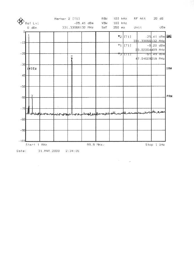
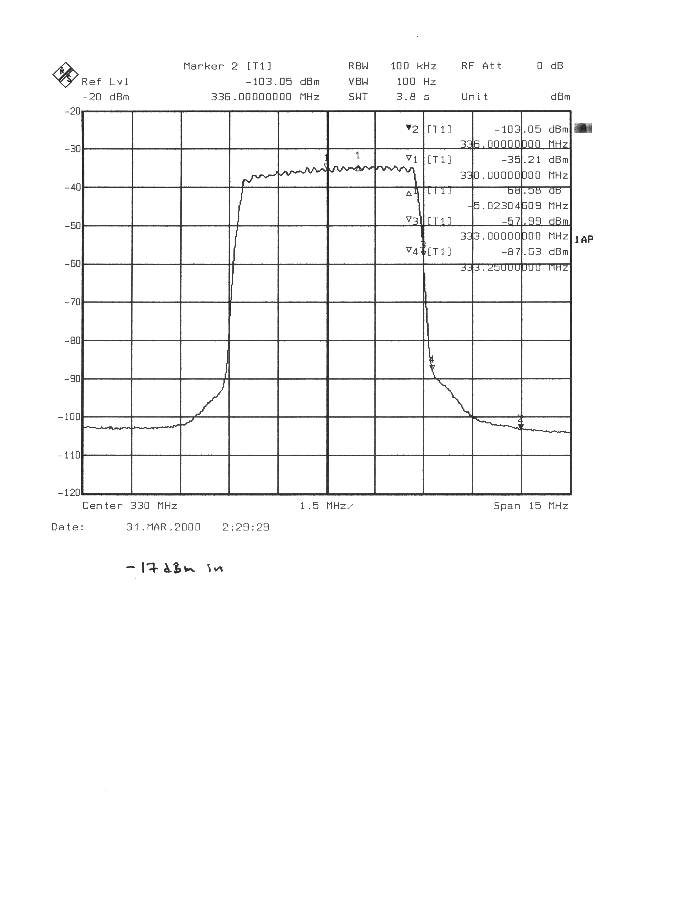
Figure 3. BW=6 MHz SX1121 output spectrum Po=18 dBm Figure 4. BW=6 MHz Po=18 dBm Figure 4. BW=6 MHz Po=18 dBm
Test Report
Watkins Johnson.FCC ID: NTTSX1121 1 EXHIBITS EXHIBIT 1:Letter Requesting Confidentiality under Sec. 0.457(d) EXHIBIT 2: Product Description and Operation Overview EXHIBIT 3:Information for which Confidentiality is Requested Schematics Block Diagrams Theory of Operation EXHIBIT 4:Product Photographs EXHIBIT 5:User Manual and FCC ID Label EXHIBIT 6:RF Hazard Information per Sec. 1.1307 EXHIBIT 7: Report of Measurements EXHIBIT 8: Data Graphs – Emissions Masks EXHIBIT 9: Data Graphs - Out of Band Emissions EXHIBIT 10: IF Card TX Signals to RF Module Watkins Johnson.FCC ID: NTTSX1121 2 EXHIBIT 1:Letter Requesting Confidentiality under Sec. 0.457(d) Watkins Johnson.FCC ID: NTTSX1121 3 Thomas N. Cokenias EMC &Radio Approvals Test & Consulting Services for Commercial, Military, International Compliance P.O. Box 1086 El Granada, CA 94018 20 January 2000 FCC Laboratory 7435 Oakland Mills Road Columbia, MD 21046 Attention: Application Examiner Reviewing Engineer Re: Request for confidentiality per Section 0.459 of FCC Rules Applicant: Watkins Johnson. FCC ID: NTTSX1121 To whom it may concern, Request is hereby submitted, on behalf of my client Watkins Johnson, to withhold from public review certain portions of the application for equipment certification for the referenced FCC identifier. In particular, the following sections of the application and report are requested to be kept confidential: Schematics Block diagrams Theory of operation (P2P Architecture) Rationale for request for confidentiality: Watkins Johnson has invested considerable time and materials in research and development to produce the referenced product. Disclosure of the confidential portions of this application to competitors would give them competitive advantage in developing similar products. The $135 fee for confidentiality has been submitted along with the fee for certification. If you have questions or need further information, please contact the undersigned. Sincerely, THOMAS N. COKENIAS EMC Consultant/Agent for Watkins Johnson. Watkins Johnson.FCC ID: NTTSX1121 4 Tel 650 726 1263 fax 650 726 [email protected] Watkins Johnson.FCC ID: NTTSX1121 5 EXHIBIT 2:Product Description and Operation Overview Watkins Johnson.FCC ID: NTTSX1121 6 The Watkins Johnson FCC ID: NTTSX1121 is a MMDS transceiver operating under the provisions of Part 21 of the Rules. Model SX1121 is subscriber or customer premises equipment (CPE). Refer to the system module diagram below: Product development strategy is to follow a modular approach. Digital data I/O for the initial version of the system will be a line card that will fit into a standard Cisco router chassis. For test purposes, a Tektronix arbitrary waveform generator will simulate the signal output of the router/line card combination. The IDU IF card up-link performs the modulation functions of the system. A 330 MHz signal is modulated with the digital data stream using Orthogonal Frequency Division Multiplexing (OFDM) techniques. The system is capable of producing channel bandwidths in 1.5 MHz multiples. The system will be configurable for use with 1.5, 3, and 6 MHz channel bandwidths. Digitaldata I/O ARB IDU IF Card RS 232 Cable PC Controlle r -48volts ODU RF Head RS 232 Cable Bias “T” Watkins Johnson.FCC ID: NTTSX1121 7 For the down-link signal, the IF card demodulates the receiver IF signal from the RF head and routes the demodulated digital information to the digital I/O card. It is anticipated that the IDU IF card will be used with a number of different RF heads, but will provide the same kind of OFDM modulation, the same IF signals, and at the same channel spacing as will be provided for the present application. The IDU output RF spectrum is shown for 6 MHz channels in Exhibit 11. The bias “T” provides DC and the 330 MHz IF signal on a single coaxial cable for routing to the RF head. The ODU RF head produces the RF transmit link at 2.5 – 2.7 GHz , and houses the receiver LNAs, receiver local oscillator, and the receiver IF bandpass filters and IF amplifiers. The RF head also houses the TX-RF diplexer. The PC controller and RS 232 cables are for system control and set-up for testing purposes. The antenna shown in the diagram is specified but not supplied by WJ. The –48 VDC supply shown in the diagram is telephone central office (CO) power or a customer provided supply. SPECIFICATIONS RF Head Frequency range: 2.5 – 2.7 GHz Power output:39dBm, 36 dBm, and 33 dBm Channel Bandwidth:1.5 MHz, 3 MHz, and 6 MHz configurable IF Head Frequency range:24 MHz clock, 48 MHz blanking, 330 MHz modulated carriers Power output:-13 dBm nominal (programmable) A detailed description of the theory of operation and product configuration is found in the attached document, rf hea~1.doc. Watkins Johnson.FCC ID: NTTSX1121 8 EXHIBIT 3:Information for which Confidentiality is Requested Schematics Block Diagrams Theory of Operations Watkins Johnson.FCC ID: NTTSX1121 9 Schematics - see separate attachment Watkins Johnson.FCC ID: NTTSX1121 10 Block Diagram - see separate attachment Watkins Johnson.FCC ID: NTTSX1121 11 Theory of Operation - see separate attachment: rf hea~1.doc Watkins Johnson.FCC ID: NTTSX1121 12 EXHIBIT 4: Product Photographs - see separate attachments Watkins Johnson.FCC ID: NTTSX1121 13 EXHIBIT 5:User Manual and FCC ID Label - see separate attachments Watkins Johnson.FCC ID: NTTSX1121 14 EXHIBIT 6: RF Hazard Information Per Sec. 1.1307 For transmitters operating in the 2.5-2.7 GHz frequency range, paragraph 1.1310 limits maximum permissible exposure (MPE) to 1 mW/cm2 for uncontrolled environments, and 5 mW/cm2 for controlled environments. The maximum distance from the antenna at which MPE is met or exceeded is calculated from the equation relating field strength in V/m, transmit power in watts, transmit antenna gain, and separation distance in meters: E,V/m = ( √ (30*P*G))/dPower density, mW/m2 = E 2 /3770 E for MPE 1mW/m2 = 61.4 V/md, meters = ( √ (30*P*G))/61.4 Watkins Johnson does not pro…
Text truncated - open the document above for the full version.
Contact Information
Applicant
Tim Buchner(Strategic Marketing)
Technical Contact
T.N. Cokenias ConsultingThomas N Cokenias
[email protected]650 726 1263
355 El Granada Blvd · El Granada, California · United States
Non-Technical Contact
T.N. Cokenias ConsultingThomas N Cokenias
[email protected]650 726 1263
Test Firm
Cisco Systems, Inc.Daisy Poon
Technical Specifications
| # | Rule Parts | Frequency Range | Power Output | Emission | Tolerance |
|---|---|---|---|---|---|
| 3 | 21 | 2.50 GHz - 2.69 GHz | 200.00 mW | 6M00D1D | 0.001 % |
Other Applications from WJ Communications, Inc.
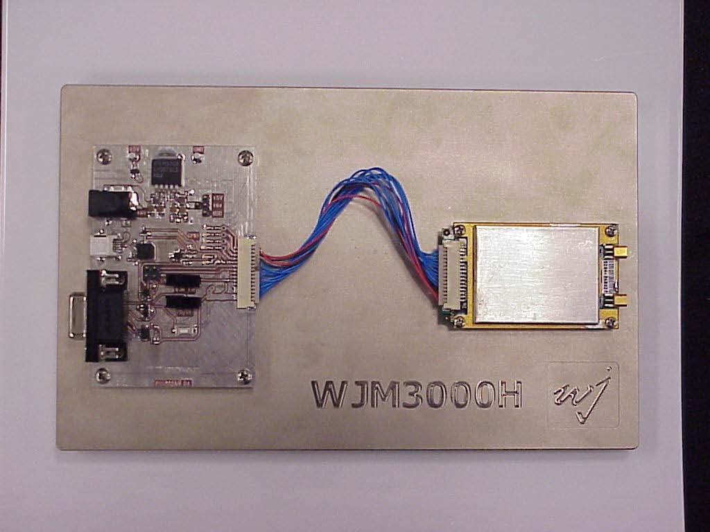
NTTWJM3000
Jan 11, 2007RFID Reader Module
Equipment Class
DSS - Part 15 Spread Spectrum Transmitter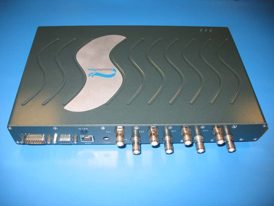
NTTSR320
Jun 20, 2006RFID Tag Reader
Equipment Class
DSS - Part 15 Spread Spectrum Transmitter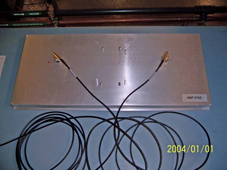
NTTWJSR22XX
Sep 12, 2005902-928MHz RFID Reader
Equipment Class
DSS - Part 15 Spread Spectrum Transmitter
NTTWJMPR7XXX
Dec 12, 2004RFID Reader
Equipment Class
DSS - Part 15 Spread Spectrum Transmitter
NTTWJMPR6XXX
Dec 09, 2004RFID Reader
Equipment Class
DSS - Part 15 Spread Spectrum Transmitter