NUF-200EVK-1202UWB Transceiver (EVK)
Humatics Corporation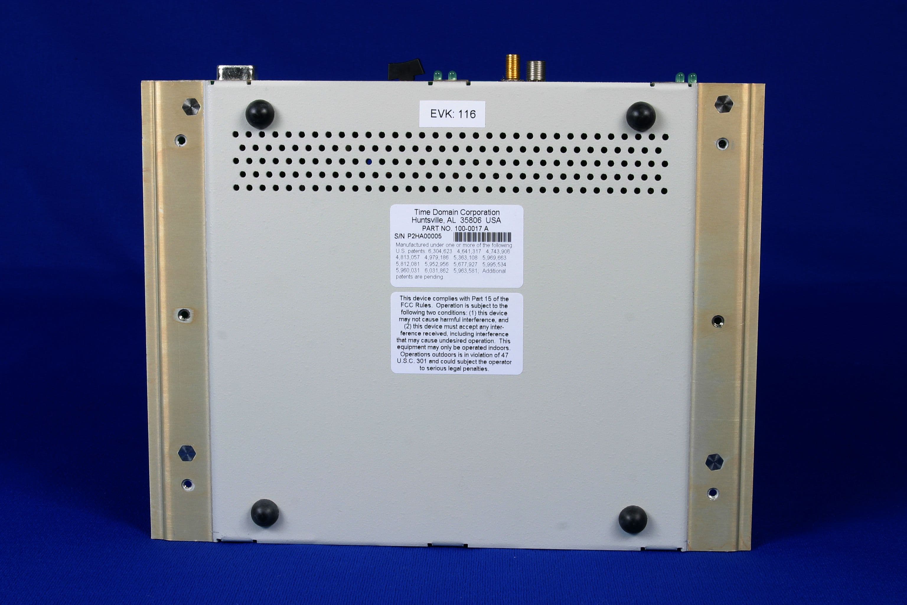
Click to zoom
Application Details
- Equipment Class
- UWB - Ultra Wideband Transmitter
- Date of Grant
- Feb 19, 2003
- Application Purpose
- Original Equipment
- Date of Application
- Dec 19, 2002
- Equipment Note
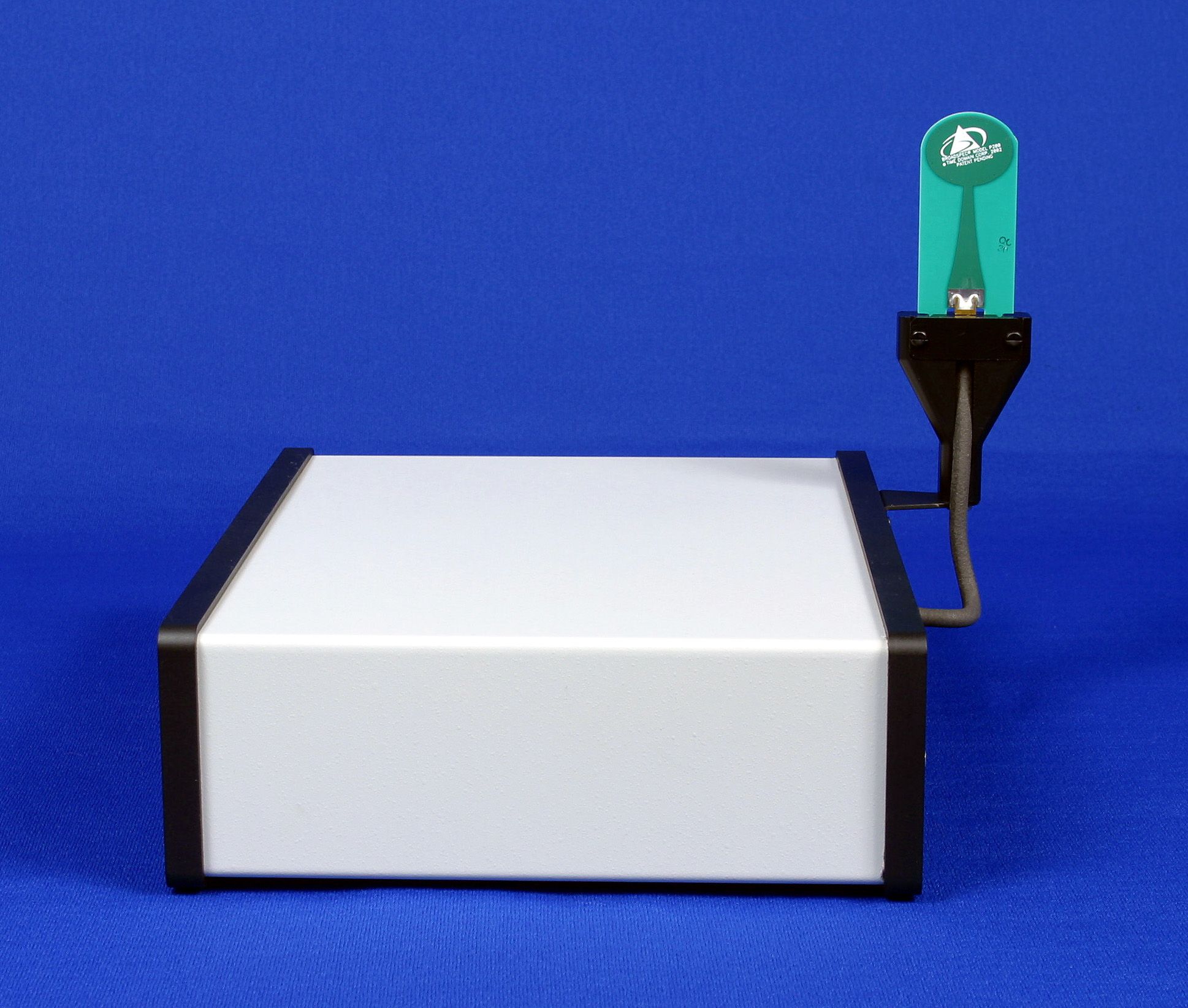
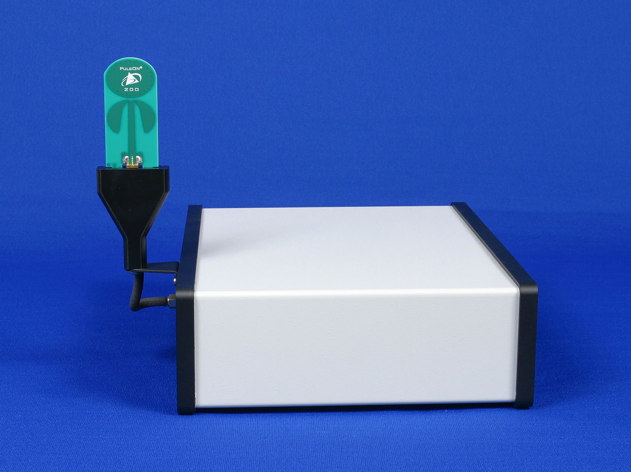
- UWB Transceiver (EVK)
- Frequency Range
- 3320.00000000 - 6380.00000000
- Company
- Humatics Corporation
- Country
- United States
Documents & Files
Document Text
Text extracted from the exhibit documents filed with the FCC. Open a document above to read the original.
Users Manual
Getting Started Guide Getting Started Guide PulsON 200 TM UWB Evaluation Kit PulsON 200 TM UWB Evaluation Kit Time Domain Corporation Cummings Research Park 7057 Old Madison Pike Huntsville, AL 35806 USA http://www.timedomain.com Tel: +1 256.428.6333 +1 888.826.8378 ext 6333 Fax: +1.256.922.0387 P200-320-0048A November 2002 Proprietary Information: Do not disclose unless authorized under the the PulsON Developers Program Nondisclosure Agreement Getting Started Guide Proprietary Information: Do not disclose unless authorized under the the PulsON Developers Program Nondisclosure Agreement 2 Nondisclosure Provisions This manual contains Time Domain Corporation’s Confidential and Proprietary Information. Members of the PulsON TM Developer’s Program and the PulsON TM Technology Program are reminded of their obligations to protect TDC Confidential and Proprietary Information. Copyright 2001-2202 Time Domain Corporation. All rights reserved. Trademarks Time Domain ® and PulsON ® are registered trademarks of Time Domain Corporation. Ethernet ® is a registered trademark of Xerox Corporation. Microsoft ® and Windows NT ®, 2000 ® ,98 ® and ME ® are registered trademarks of Microsoft Corporation. Xilinx ® is a registered trademark of Xilinx, Incorporated. “PulsON Triangle” logo, PulsON Technology Program ™ and PulsON 200 ™ are trademarks of Time Domain Corporation. MultiLINX ™ is a trademark of Xilinx, Incorporated. VxWorks TM is a registered trademark of Wind River Systems, Inc. HyperTerminal is the registered trademark of Intel Corp. Any trademarks, trade names, service marks or service names owned or registered by any other company and used in this manual are the property of its respective company. Rights Rights to use this documentation are set forth in the Terms and Conditions accompanying the Evaluation Kit Regulatory Notice This device does not comply with any RF emissions regulations in any country. Users should consult their spectrum management authorities before use. • U.S Operation : This device complies with Part 15 of the FCC Rules. Operation is subject to the following conditions: (1) this device may not cause harmful interference; (2) this device must accept any interference received, including interference that may cause undesired operation; (3) this device must be operated indoors; and (4) the emissions from equipment operated under this section shall not be intentionally directed outside of the building in which the equipment is located, such as through a window or a doorway, to perform an outside function, such as detection of people about to enter a building. Operation in disregard of these conditions is a violation of 47 U.S.C. 301 and could subject the operator to serious legal penalties • If you have questions, please consult with Time Domain Corporation before you use this device. • Non-U.S.: PulsON ® technology has not been authorized for use or commercial exploitation under the regulations of any government agency. Please confer with your government’s regulatory agency to ensure proper authorizations are obtained. Getting Started Guide 3 Introduction Congratulations on stepping in to the world of Ultra Wideband (UWB) technology! The Evaluation Kit (EVK) is the key hardware tool for UWB evaluation and application development. Within the next thirty minutes, this guide will help you set up, configure and test your PulsON 200 TM radios. The initial functionality of the EVK includes tools to examine the performance of the PulsON 200 radio and a development environment that allows users to explore the possibilities provided by UWB. This Getting Started Guide takes the user from initial radio setup through first power-up and to the radio connection to the computer interface. At the completion of this guide, you will have confirmed that the radios are functional and the correct setup configuration between the radios and the user’s computer. What is in the box? Upon receipt of your shipment, inspect the shipping container and contents. If the contents of the shipment are incomplete or if there is mechanical damage, notify Time Domain Corp. (TDC) immediately at 1-800-826-6333. TDC has supplied the following items with your shipment. Proprietary Information: Do not disclose unless authorized under the the PulsON Developers Program Nondisclosure Agreement Qty. Name Part # 2 PulsON 200 TM Radio 100-0017 2 Broadspec® Model P200 Antenna, EVK 220-0126 2 Power Supply, 90-264 VAC in/7.5 VCD out 024-0003 2 Power Cord 017-0029 1 Software CD 150-0015A 1 Documentation CD 10D-0014A Table 1: Supplied components of the Evaluation Kit Getting Started Guide Proprietary Information: Do not disclose unless authorized under the the PulsON Developers Program Nondisclosure Agreement 4 The software CD (150-0014A) contains a copy of the embedded elements already loaded on your radios as well as the necessary PC software. These elements include: • UWB Kernel (in executable form) • Performance Analysis Tool (PAT) embedded (in executable form) • PAT GUI (Self-extracting executable) • Basic Host Translator (Host API) • Flash Loader Utility The embedded code is provided should the radio software need to be reloaded. The Troubleshooting the Radio section of this Guide provides instructions for this software load. Instructions on loading the PAT GUI appear in this document. The documentation CD (10D-0015A) contains this document as well as the PulsON TM 200 UWB Evaluation Kit Users’ Manual (P200-320-0049) and the Programming Guide for the PulsON 200 TM Evaluation Kit (P200-320-0050A). Updates to these documents will be provided as functions are added. What You Will Need to Work with the Unit In order to connect to and control the PulsON 200 TM radios, the user will need at least one PC, hardware, and software as described below. • PC running Windows 2000 or Windows NT-- EVK software has been developed to work with Windows 2000 and Windows NT. The EVK software will work with Windows 98 and Windows ME operating sy…
Text truncated - open the document above for the full version.
Cover Letter(s)
Application Overview This application seeks certification of an ultra wideband device under the recently approved Part 15.517 (Technical Requirements for Indoor UWB Systems) as well as 15.209 and all other applicable sections. The UWB device is a Time Modulated-Ultra Wideband (TM-UWB) transceiver. The device is line powered. The antenna is carefully matched to the excitation waveform and is attached to the transceiver with a reverse polarity SMA connector. These connectors are difficult to obtain, which prevents the replacement of the antenna with an unapproved antenna. Intertek Testing Services in Atlanta GA measured the device in accordance with the measurement procedures identified in the appendices of the FCC’s UWB Report and Order (FCC 02-48). Any deviations from those procedures have been annotated and explained.
Cover Letter(s)
Time Domain Corporation Cummings Research Park 7057 Old Madison Pike Huntsville, Alabama 35806 February 3, 2003 Mr. Joe Dichoso ([email protected]) Senior Engineer, FCC Application Processing Branch FCC Laboratory Columbia, MD Re: FCC ID NUF-200EVK-1202 Applicant: Time Domain Corporation Correspondence Reference Number: 24735 731 Confirmation Number: EA204856 Dear Joe: Below are your six numbered questions and our response. Should you have any questions, please call me (256 428 6317). 1) With regard to the Block diagrams, provide the signal path and frequency at each block per Section 2.1033(b)5. At each block, also provide the tuning range(s) and intermediate frequency(ies) at each block. TDC Response : We have revised the block diagram. The revision will be submitted separately because it contains confidential information. 2) The internal photo's cannot be held confidential since they would be available to anyone purchasing the device. Please remove this from the confidential request. External photographs are not confidential. TDC Response : TDC is only selling these devices to carefully selected customers. These customers must sign an agreement that forbids them from disassembling the device. Therefore, our customers will not have access to the internal components of this system unless they violate the terms of the agreement. 3) The user's manual was marked confidential. The user's manual cannot be held confidential. Please remove the confidential material in the manual and resubmit. TDC Response : The Users’ Manual contains significant confidential information. Again, customers are screened during the sales process to ensure that competitive access to our specifications and designs is minimized. Making this document available via the FCC website would make the information readily accessible to our competitors. We continue to request that this information remain confidential. Mr. J. Dichoso RE: FCC ID NUF-200EVK-1202 Correspondence Reference Number: 24735 Page 2 www.time-domain.com 1.256.922.9229 phone 1.256.922-0387 fax 4) Verify whether or not the PRF is adjustable. If it is, additional tests may be requested. TDC Response : The PRF is not adjustable. 5) The UWB bandwidth measurements were made only from 3-11GHz. The test must investigate emissions in the same frequency range as radiated emissions tests. In addition, the UWB bandwidth test procedure did not indicate whether the antenna polarization was changed for the data submitted. What antenna was used for the UWB measurements? If a horn antenna was used, verify whether the horn antenna was adjusted, when it was raised 1 to 4 meters, so that it always points at the area of the device in order to receive the maximum emission from the device. TDC Response : UWB emissions were measured over the whole range required for compliance testing as shown in Figures 5.1 through 5.4 of the report from Intertek Testing Services. Section 2.2 of that report identifies the equipment used for the testing. Two horns were used. The EMCO 3116 (18 to 40 GHz) was used over that range. The AH Systems SAS 200/571 (0.7 to 18 GHz) was used over the appropriate range for that antenna. The antenna was bore sight when it started at 1 meter but was not adjusted as it rose to the 4 meter position. 6) For all emissions that are over the UWB limits but are below the 15.209 limits that you state are attributed to digital circuitry. Please identify the source of these emissions from the schematics or block diagrams. TDC Response : Some of the frequencies listed on pages 15 and 16 of the ITS report are probably harmonics of the 19.2 MHz system clock. The table below identifies those emissions and the harmonic number. Frequency (MHz) Harmonic Number 921.520 48 th 1132.700 59 th 1152.000 60 th 1228.875 64 th 1382.467 72 nd Mr. J. Dichoso RE: FCC ID NUF-200EVK-1202 Correspondence Reference Number: 24735 Page 3 www.time-domain.com 1.256.922.9229 phone 1.256.922-0387 fax There are five other clock frequencies within the radio that could be generating the other signals in question. For example, the 3.69 MHz clock is the likely source of the 55.263 MHz and the 66.250 MHz signals (15 th and 18 th harmonics, respectively); while the 25 MHz clock is the likely source of the 1950 MHz and the 2300 MHz signals (the 78 th and 92 nd harmonics respectively). There can be no doubt that these emissions are not related to the UWB emissions, since all UWB trigger signals are noise coded and, therefore, would not create spectral lines. Thus, these signal are in compliance with the rules. As you may know, I am scheduled to bring this device as well as another device up to the laboratory on Wednesday morning the 5 th of February to demonstrate them and leave them behind for your testing. I look forward to meeting you at that time and discussing this further if necessary. Yours truly, s/Keven Trach Compliance Engineer Time Domain Corp. Phone: 256 428 317FAX: 256 922 0387 [email protected]
Cover Letter(s)
Time Domain Corporation Cummings Res earch Par k 7057 Old Madison Pike Huntsville, Alabama 35806 February 11, 2003 Filed Electronically Mr. Joe Dichoso ([email protected]) Senior Engineer, FCC Application Processing Branch FCC Laboratory Columbia, MD Re: FCC ID NUF-200EVK-1202 Applicant: Time Domain Corporation Correspondence Reference Number: 24735 731 Confirmation Number: EA204856 Dear Joe: Below is the question that we discussed and our response. Should you need anything further, please call me. FCC Question : When the horn antenna was used did you point the antenna directly at the device when it was raised from 1 to 4 meters, in order to receive the maximum emission? TDC Response : The procedure used by Intertek Testing Services was in full compliance with ANSI C63.4 (1992). It is the same procedure used for all Part 15 devices undergoing equipment authorization testing. ITS measured the EVK’s emissions with their horn antenna pointed directly at the device when it was 1 meter above the ground plane. This antenna orientation was fixed during the test. Thus, the horn antenna did not tilt as the mast moved upward. We performed this same standardized measurement procedure at Time Domain and then repeated the procedure but adjusted the antenna orientation so that it was pointing directly at the device at all heights. We found that when the antenna pointed directly at the device at all times the emissions were higher by at most 0.5 dB and so the device still would be within FCC limits. Yours truly, s/Keven Trach Compliance Engineer Time Domain Corp. Phone: 256 428 6317 FAX: 256 428 6710 [email protected]
Cover Letter(s)
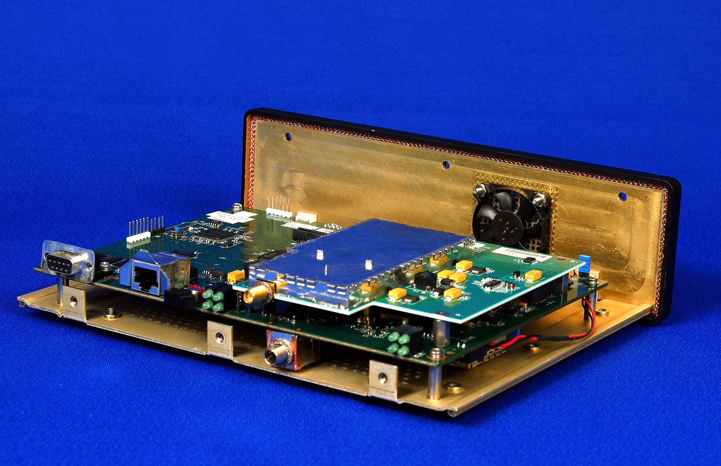
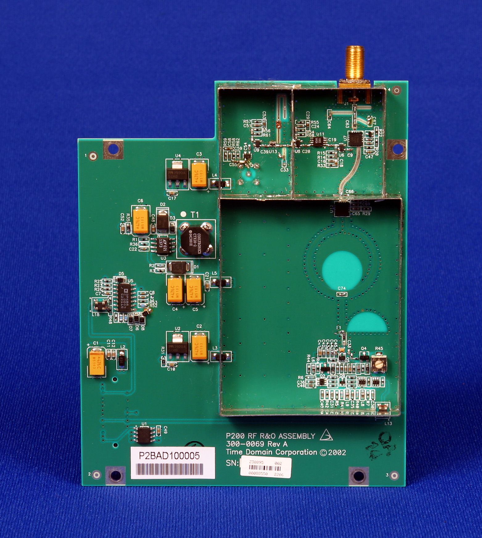
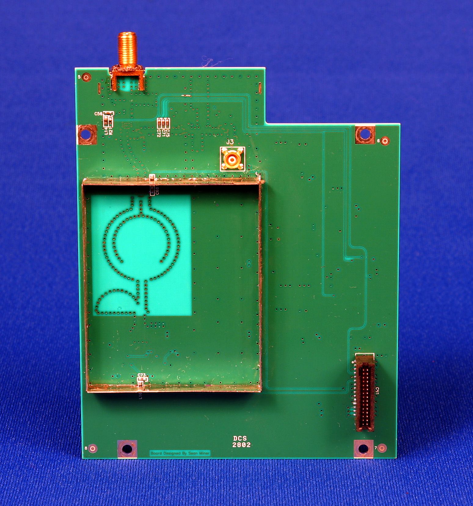
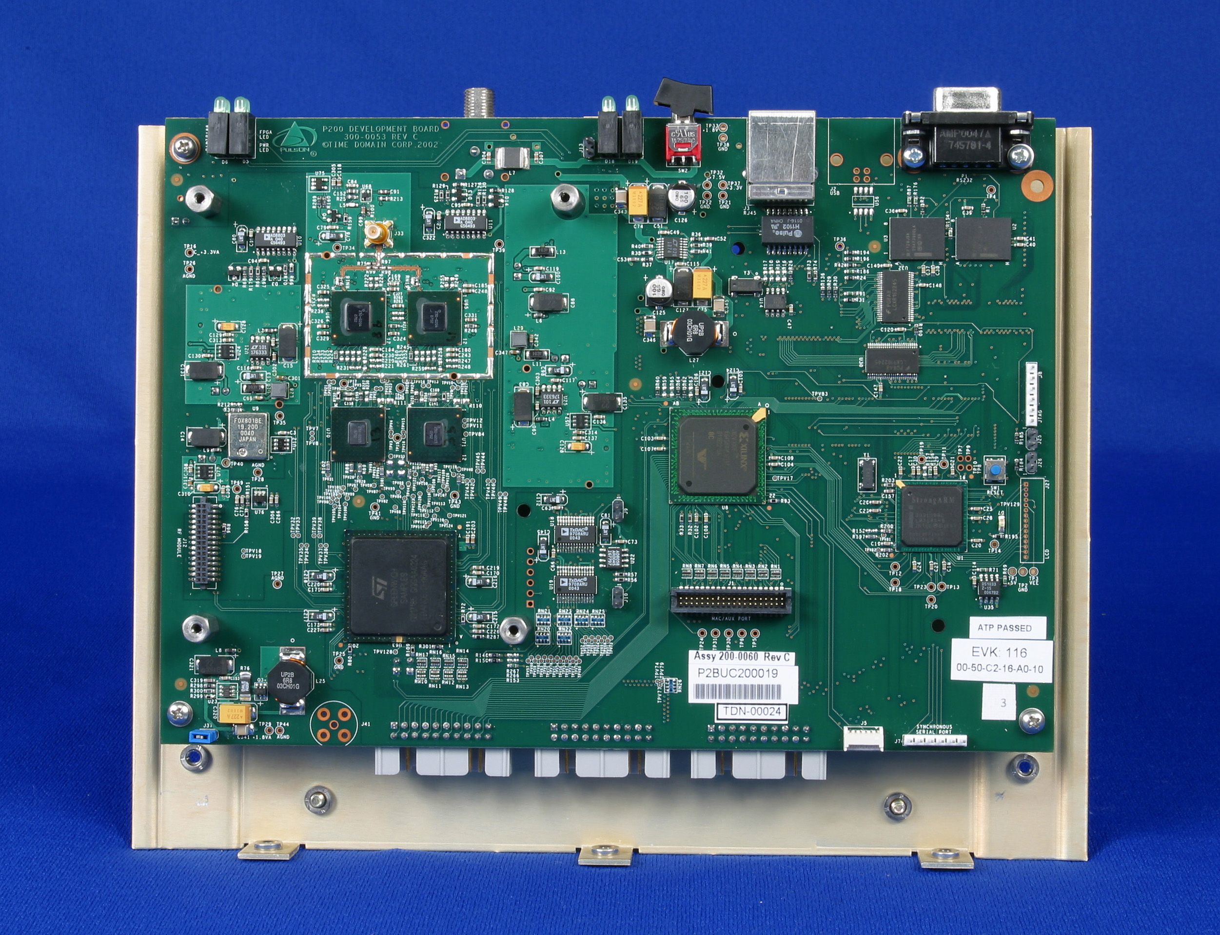
Time Domain Corporation Cummings Res earch Par k 7057 Old Madison Pike Huntsville, Alabama 35806 February 14, 2003 Mr. Joe Dichoso ([email protected]) Senior Engineer, FCC Application Processing Branch FCC Laboratory Columbia, MD Re: FCC ID NUF-200EVK-1202 Applicant: Time Domain Corporation Correspondence Reference Number: 24735 731 Confirmation Number: EA204856 Dear Joe: Time Domain had originally requested that the internal photograph and the users manual for the EVK be held confidential. After further discussion Time Domain has decided to submit a new users manual and not request it to be held confidential. Time Domain would also like to remove the confidentiality request from the “internal photos” as it had originally submitted. Time Domain would however like for the schematics and block diagrams to remain confidential as originally filed. Yours truly, s/Keven Trach Compliance Engineer Time Domain Corp. Phone: 256 428 317FAX: 256 922 0387 [email protected]
Cover Letter(s)
Time Domain Corporation Cummings Research Park 7057 Old Madison Pike Huntsville, Alabama 35806 February 20, 2003 Mr. Joe Dichoso ([email protected]) Senior Engineer, FCC Application Processing Branch FCC Laboratory Columbia, MD Re: FCC ID NUF-200EVK-1202 Applicant: Time Domain Corporation Correspondence Reference Number: 24826 731 Confirmation Number: EA204856 Dear Joe: Below I have listed the problem with the newly submitted manual and our response. Should you have any questions, please call me (256 428 6317). The new manual that was recently submitted refers to a SMA connector on the antenna port. This is a standard connector and does not comply with Section 15.203. Please address/correct accordingly. Response : We have revised the Manual by removing the “SMA” part and referring to it as a connector. The antenna port on the EVK does not have a standard antenna jack. This connection is a unique special order connector and therefore meets the requirements in Section 15.203. The connector that is used is listed below. Name: SMA Reverse Polarity Manufacturer: Johnson Components Part Number: 142-4701-801 This is the same antenna connector as previously approved on the Signal Generator TAG (NUF-200SGT-0702). Yours truly, s/Keven Trach Compliance Engineer Time Domain Corp. Phone: 256 428 317FAX: 256 922 0387 [email protected]
ID Label/Location Info
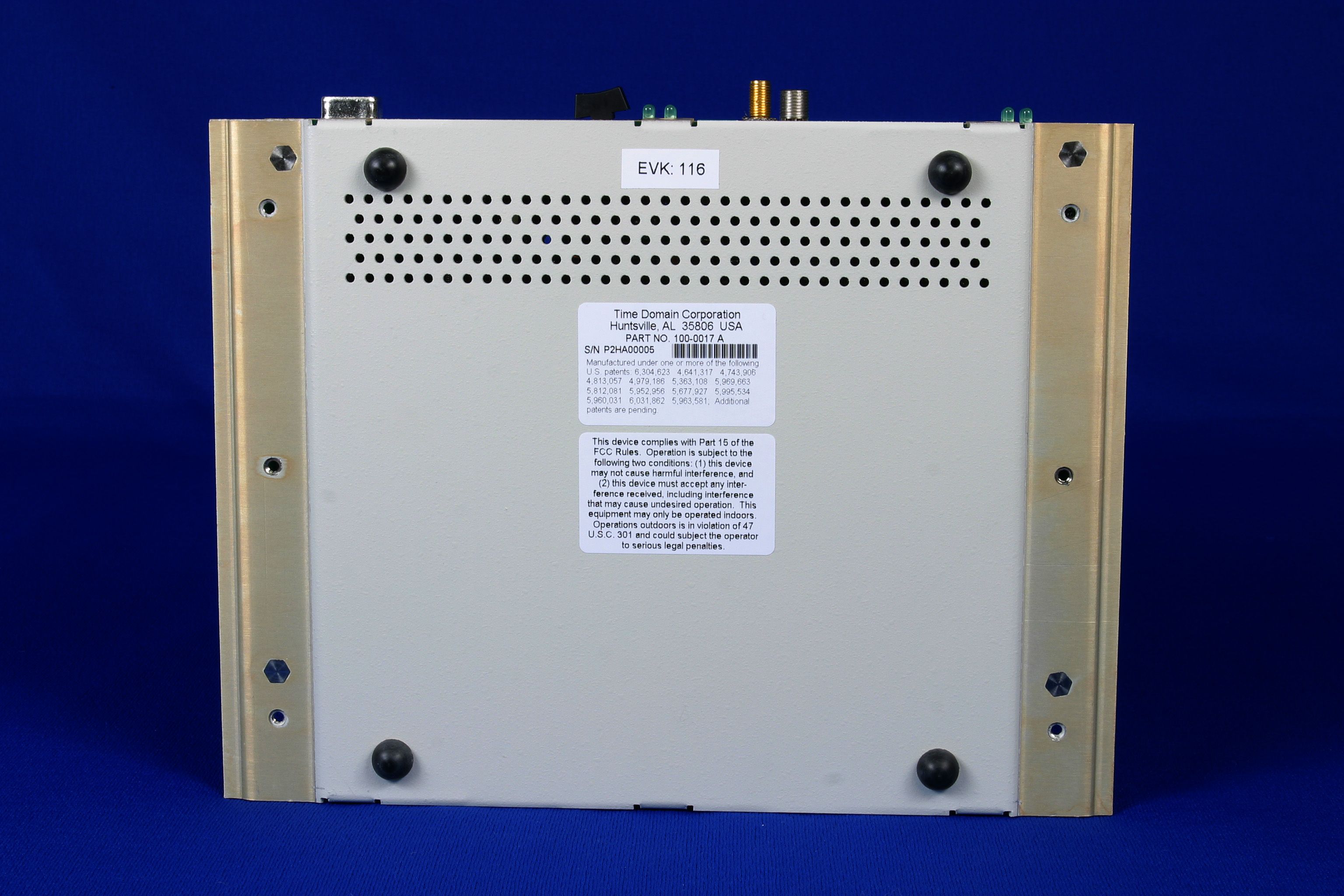
S/N P2HA000000 PART NO.: 100-0017A Huntsville, AL 35806 USA Time Domain Corporation ALL DIMENSIONS ARE IN INCHES UNLESS SPECIFIED. DIMENSIONAL TOLERANCES UNLESS OTHERWISE SPECIFIED: 2 PLACE ±.01 3 PLACE ±.0054 PLACE ±.0005 ANGLES ±0.5° DO NOT SCALE DRAWING FILE NAME: ORIGINATORENGINEERAPPROVEDRELEASED THIS DESIGN AND PRINT IS THE PROPERTY OF TIME DOMAIN CORPORATION THIS DOCUMENT CONTAINS PROPRIETARY INFORMATION AND IS LOANED IN CONFIDENCE. THIS DOCUMENT IS SUBJECT TO RETURN UPON DEMAND ON THE EXPRESS CONDITION THAT IT WILLNOT BE USED IN ANY WAY NOT AUTHORIZED BY TIME DOMAIN CORPORATION. TIME DOMAIN THE PULSE OF THE FUTURE Huntsville, AL B1 3rd ANGLE PROJECTION APPROVALS DATE OF 320-0046 32A-0046 B LABEL, PRINTED, PRODUCT ID, EVK 1 1 ~ J. ANDERSON 11/15/02 J. ANDERSON 11-20-02 B. CALDWELL 11-20-02 32A-0046B Label EVK ID.DWG
ID Label/Location Info
ALL DIMENSIONS ARE IN INCHES UNLESS SPECIFIED. DIMENSIONAL TOLERANCES UNLESS OTHERWISE SPECIFIED: 2 PLACE ±.01 3 PLACE ±.0054 PLACE ±.0005 ANGLES ±0.5° DO NOT SCALE DRAWING FILE NAME: ORIGINATORENGINEERAPPROVEDRELEASED THIS DESIGN AND PRINT IS THE PROPERTY OF TIME DOMAIN CORPORATION THIS DOCUMENT CONTAINS PROPRIETARY INFORMATION AND IS LOANED IN CONFIDENCE. THIS DOCUMENT IS SUBJECT TO RETURN UPON DEMAND ON THE EXPRESS CONDITION THAT IT WILLNOT BE USED IN ANY WAY NOT AUTHORIZED BY TIME DOMAIN CORPORATION. TIME DOMAIN THE PULSE OF THE FUTURE Huntsville, AL B1 3rd ANGLE PROJECTION APPROVALS DATE OF 320-0031 32A-0031 B LABEL, PRINTED, FCC NOTICE, TAG 1 1 ~ J. ANDERSON 01/16/2002 32A-0031B Label FCC Notice.DWG
ID Label/Location Info
100-0017 10A-0017 A ASS'Y, P200 EVK 4 4 ~ 100-0017A SHEET4.DWG
Operational Description
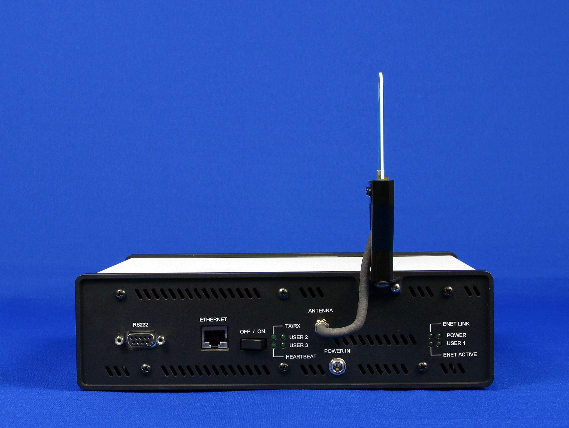
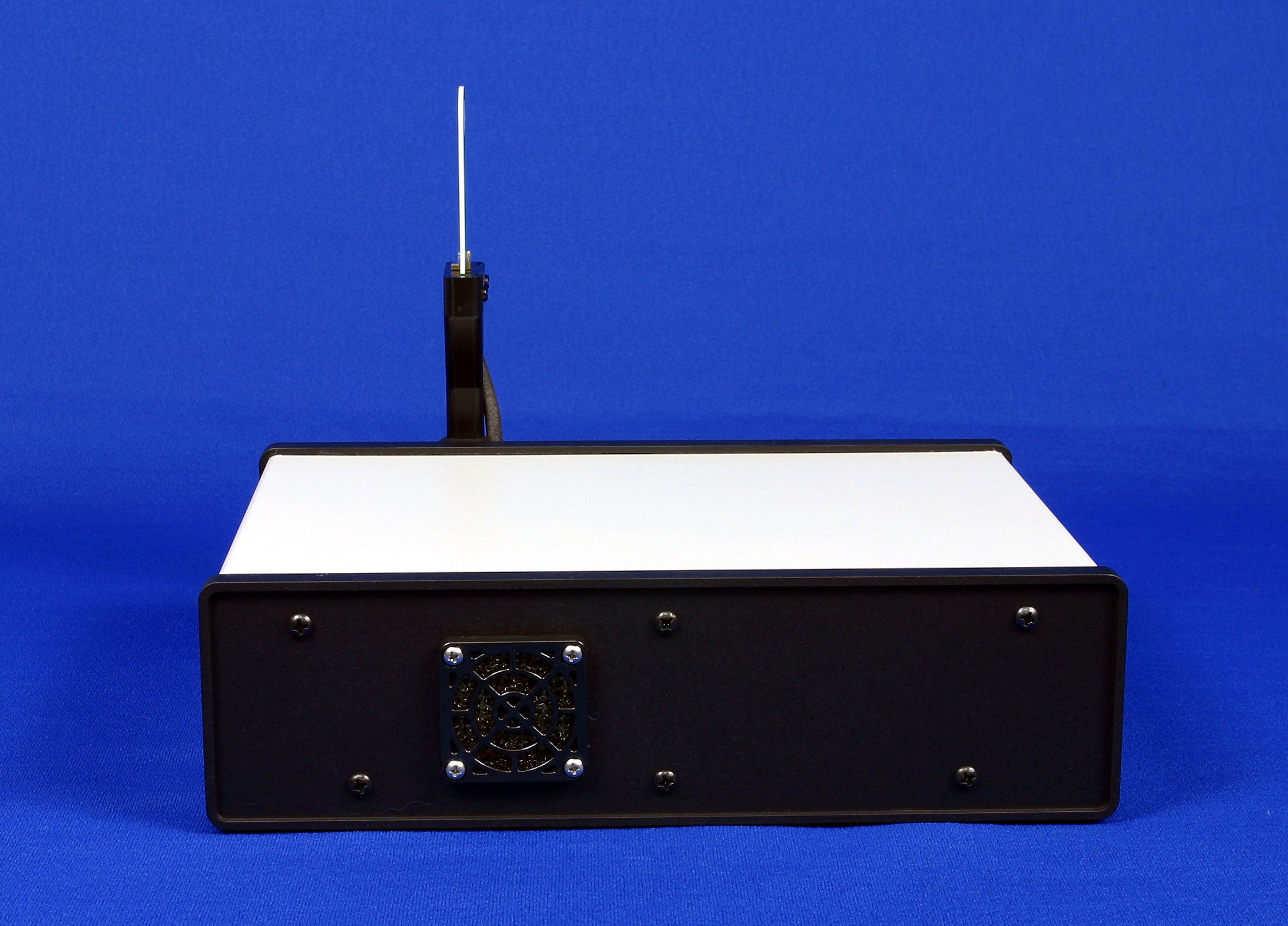
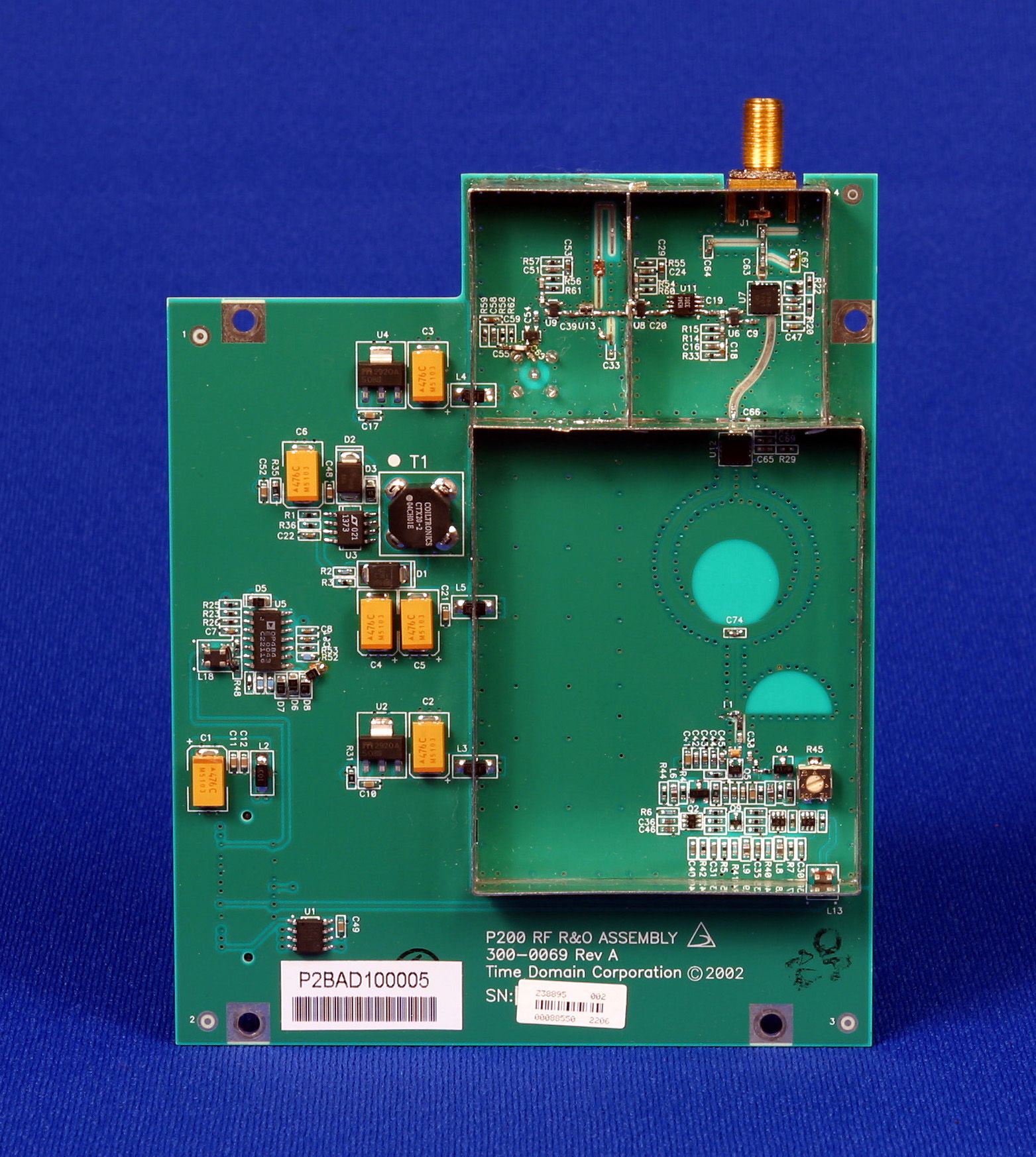
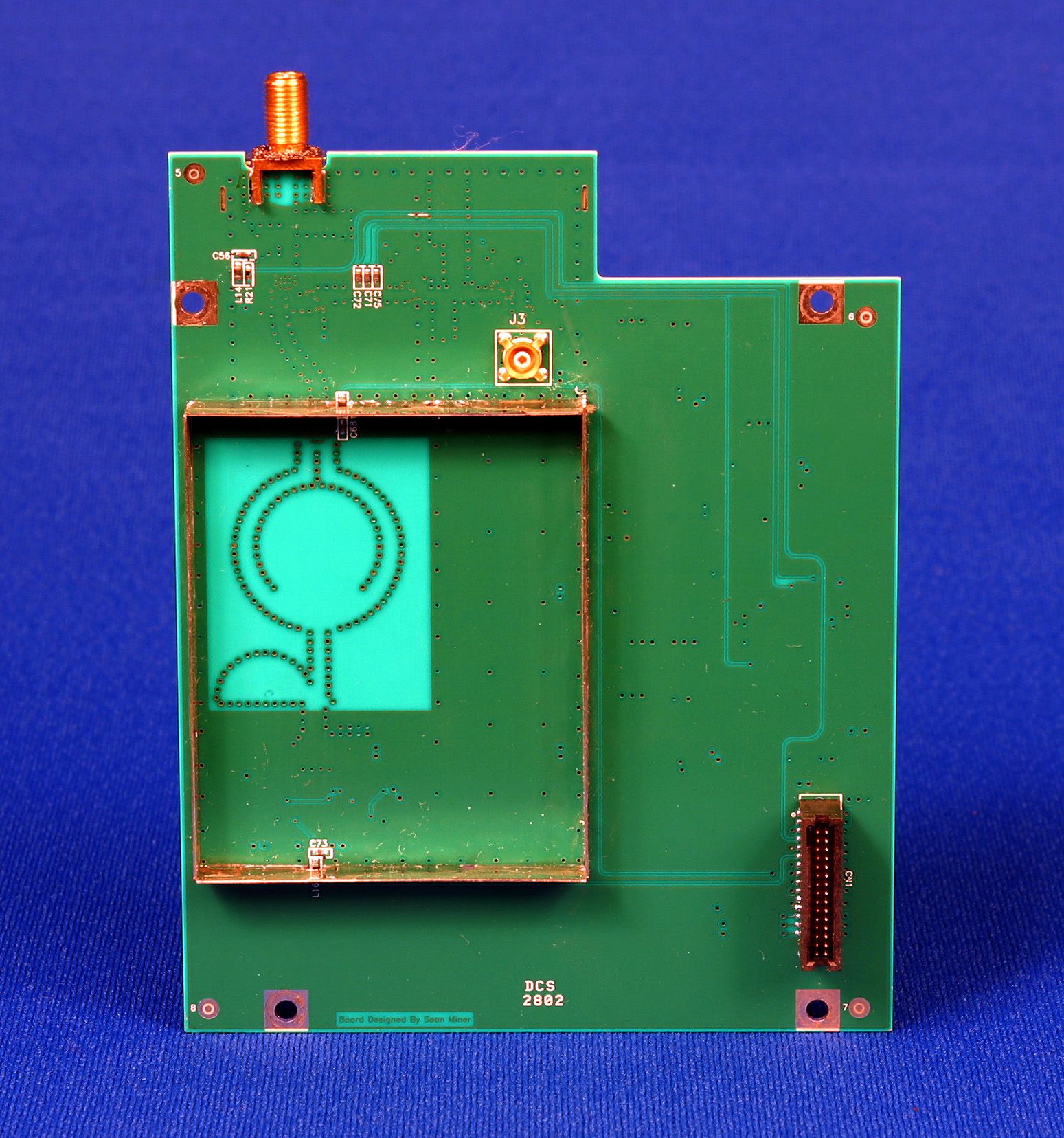
The PulsON 200 Evaluation Kit (EVK) contains 2 PulsON 200 radios (transceivers), 2 powers supplies, 2 antenna assemblies and associated software and documentation. The EVK is designed to enable Time Domain Corporation (TDC) partners to both evaluate Ultra Wideband Technology (UWB) and to develop prototype applications. These activities are critical steps in creating UWB products for communications, tracking and radar. Initially the user of the EVK will work with the TDC developed Performance Analysis Tool (PAT) software package to collect propagation data for link budget and channel assessment. Using PAT, the radio can be set up to transmit a standard BER pattern at a selectable raw data rate and using a TDC provided transmission code file. The receiving radio displays parameters such as E b , N eff , receive data rate, acquisition percentage, and bit error rate. The user can also display a scan of the captured waveform as well as a scan of the ambient environment. This data will allow a user to determine if UWB will provide acceptable performance in their particular target application. Once a system application is found to be feasible, the EVK provides both a host and embedded software development environment for early implementation prototyping. An embedded application layer which extracts more detailed functionality is provide for users wishing to develop on the host or PC side. Limited access to the TDC UWB Kernel is also provided for users that want to develop everything at an embedded level. It is important to note that user cannot at either level modify the fundamental signal shape, strength or spectral properties, nor can the user place the radio in a mode that spectrally violate the FCC regulations.
Test Report
EMC Report for Time Domain Corporation on the EVK File: 0224466uwb.doc Page 1 of 30 TEST REPORT Report Number: 0224466uwb.doc Revision 1 Project Number: 3034466 December 16, 2002 Evaluation of the EVK Model Number: 100-0017 A to CFR 47 Part 15, Subpart F For Time Domain Corporation Test Performed by: Test Authorized by: Intertek Testing Services 1950 Evergreen Blvd, Suite 100 Duluth, GA 30096 Time Domain Corporation 7057 Old Madison Pike Huntsville, AL 35806 All services undertaken are subject to the following general policy: Reports are submitted for exclusive use of the client to whom they are addressed. Their significance is subject to the adequacy and representative character of the samples and to the comprehensiveness of the tests, examinations or surveys made. This report shall not be reproduced except in full, without written consent of Intertek Testing Services NA Inc. This report must not be used to claim product endorsement by A2LA, NIST nor any other agency of the U.S. Government. Intertek Testing Services EMC Report for Time Domain Corporation on the EVK File: 0224466uwb.doc Page 2 of 30 TABLE OF CONTENTS EXECUTIVE SUMMARY ..................................................................................................................................... 3 1 JOB DESCRIPTION...................................................................................................................................... 4 1.1 CLIENT INFORMATION.................................................................................................................................. 4 1.2 TEST PLAN REFERENCE: ...............................................................................................................................4 1.3 EQUIPMENT UNDER TEST (EUT).................................................................................................................. 4 1.3.1 System Support Equipment ................................................................................................................. 5 1.3.2 Cables associated with EUT ................................................................................................................ 5 1.3.3 System Block Diagram ........................................................................................................................ 6 1.3.4 Justification.......................................................................................................................................... 7 1.3.5 Mode(s) of operation ........................................................................................................................... 7 1.4 MODIFICATIONS REQUIRED FOR COMPLIANCE.............................................................................................. 7 2 TEST ENVIRONMENT ................................................................................................................................ 8 2.1 TEST FACILITY............................................................................................................................................. 8 2.2 TEST EQUIPMENT......................................................................................................................................... 8 2.3 MEASUREMENT CALCULATIONS.................................................................................................................. 9 2.3.1 Example Field Strength Calculation .................................................................................................... 9 2.3.2 EIRP Calculations................................................................................................................................ 9 2.4 MEASUREMENT UNCERTAINTY.................................................................................................................... 10 3 OPERATIONAL LIMITATIONS ................................................................................................................ 11 4 UWB BANDWIDTH ...................................................................................................................................... 12 4.1 TEST PROCEDURE........................................................................................................................................ 12 4.2 TEST RESULTS.............................................................................................................................................. 12 5 RADIATED EMISSIONS .............................................................................................................................. 13 5.1 TEST LIMITS................................................................................................................................................. 13 5.2 TEST PROCEDURE........................................................................................................................................ 14 5.3 TEST RESULTS.............................................................................................................................................. 15 5.4 TEST CONFIGURATION PHOTOGRAPH........................................................................................................... 19 6 RADIATED EMISSIONS IN GPS BANDS .................................................................................................21 6.1 TEST LIMITS................................................................................................................................................. 21 6.2 TEST PROCEDURE........................................................................................................................................ 21 6.3 TEST RESULTS.............................................................................................................................................. 21 7 PEAK EMISSION WITHIN A 50 MHZ BANDWIDTH ............................................................................ 24 7.1 TEST LI…
Text truncated - open the document above for the full version.
Contact Information
Applicant
Alan Petroff
Technical Contact
Time Domain Corp.Keven B Trach
[email protected]256-428-6317
7057 Old Madison Pike · Huntsville, Alabama · United States
Non-Technical Contact
Time Domain Corp.Bonnie Caldwell
[email protected]2564286483
Test Firm
Intertek Testing ServicesDavid Schramm
Technical Specifications
| # | Rule Parts | Frequency Range | Power Output |
|---|---|---|---|
| 1 | 15F | 3.32 GHz - 6.38 GHz | - |
Other Applications from Humatics Corporation
NUF-C445-A
Feb 25, 2020Ultra wideband radio
Equipment Class
UWB - Ultra Wideband Transmitter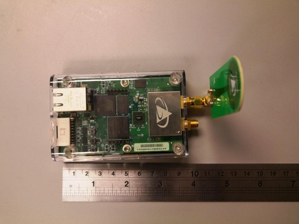
NUF-P440-A
Jan 26, 2016Ultra Wideband (UWB) radio transceiver
Equipment Class
UWB - Ultra Wideband Transmitter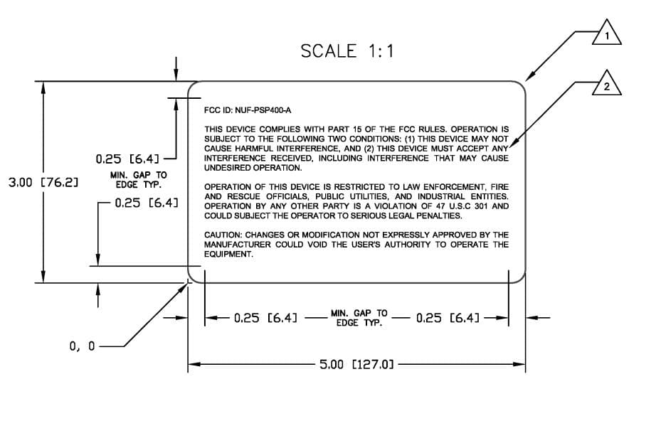
NUF-PSP400-A
Dec 21, 2014UWB Radar Surveillance System
Equipment Class
UWB - Ultra Wideband Transmitter
NUF-P412-A
Feb 03, 2013P412 Ultra Wideband radio transceiver
Equipment Class
UWB - Ultra Wideband Transmitter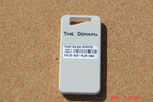
NUF-PLUS-0309
Apr 19, 2009PLUS Name Tag
Equipment Class
WBT - Wideband Transmitter