NUF-P412-AP412 Ultra Wideband radio transceiver
Humatics Corporation
Click to zoom
Application Details
- Equipment Class
- UWB - Ultra Wideband Transmitter
- Date of Grant
- Feb 03, 2013
- Application Purpose
- Original Equipment
- Date of Application
- Nov 27, 2012
- Equipment Note
- P412 Ultra Wideband radio transceiver
- Frequency Range
- 3247.00000000 - 5152.00000000
- Company
- Humatics Corporation
- Country
- United States
Documents & Files
Document Text
Text extracted from the exhibit documents filed with the FCC. Open a document above to read the original.
Users Manual
User’s Manual and Data Sheet PulsON ® 412 DRAFT Final Version available Jan 31, 2013 Nov 2012 TIME DOMAIN ® Cummings Research Park 4955 Corporate Drive Suite 101 Huntsville, AL 35805 USA http://www.timedomain.com Tel: +1 256.922.9229 +1 888.826.8378 Fax: +1.256.922.0387 2 P412 User’s Manual & Data Sheet Copyright All rights reserved. Time Domain ® 2001-2012. All rights reserved. Trademarks Time Domain ® , PulsON ® , and “PulsON Triangle” logo are registered trademarks of Time Domain. Microsoft ® and Windows XP ®, Windows Vista ® , and Windows 7 ® are registered trademarks of Microsoft Corporation. Any trademarks, trade names, service marks or service names owned or registered by any other company and used in this manual are the property of its respective company. Rights Rights to use this documentation are set forth in the PulsON Products Terms and Conditions of Sale. P412 User’s Manual & Data Sheet 3 Overview This document is the user’s manual and data sheet for the Time Domain PulsON 412 (“P412”) Ultra Wideband (UWB) ranging radio transceiver. The document is divided into the following sections. Section 1 Summary and Theory of Operation Section 2 Using a P412 as a Ranging Radio Section 3 Hardware Block Diagram Section 4 Interfaces Section 5 Mechanical Section 6 Performance Specs Section 7 Broadspec Antenna Section 8 FCC Compliance Section 9 Export Restrictions 1 Summary and Theory of Operation The P412 is an Ultra Wideband (UWB) radio transceiver that provides the following functions: • It accurately and reliably measures the distance between two P412s and provides these measurements at a high update rate. • It supports two different range measurement techniques (Two-Way Time-of-Flight and Coarse Range Estimation). • It communicates data between two or more P412s. Time Domain’s PulsON P412 is a ruggedized, industrial UWB platform. The most obvious and important characteristics of the device relative to industrial operation are listed below: • The electrical interface to the unit through USB, Serial or CAN • All components are rated for industrial temperature (-40C to +85C) • Fan is not required for cooling. • For best performance, the user must provide a heat sink to insure that the unit does not overheat • The board is provided with nine large (#6) mounting holes that insure that the unit will survive and operate in most high vibration environments • RF filtering provides superior operation in the presence of 2.4GHz and 5.8GHz • The UWB emissions have been tested and comply with FCC 15.519 which is the most stringent of the FCC UWB limits • The digital emissions have been tested and comply with the FCC 15.109(b) (“Class A digital device”) which limits use of the P412 to commercial and industrial uses only The P412 is an Ultra Wideband radio that coherently transmits and receives trains of individual RF pulses at a nominal rate of 10 MHz. Figure 1 provides a notional example of a typical UWB pulse in both the time and frequency domain. Pulses are transmitted as coded trains of pulses. Coding is accomplished either by pseudo-randomly shifting the pulse phase or inter pulse transmission time. By transmitting and receiving pulses coherently, the P412 can integrate multiple pulses and thereby increase the received signal to noise ratio. Integration can therefore be used to increase robustness and or operational range. 4 P412 User’s Manual & Data Sheet Figure 1: Notional UWB pulse in both time and frequency domain. The P412 measures distance using a technique called Two Way Time of Flight. In this approach the radio requesting the range measurement (the Requestor) will transmit a packet of pulses that will be received by one or more units (the Responders). The responder will then measure the leading edge of the waveform relative to the radio lock spot and transmit this information in a return (or responding) packet. The Requestor will then measure the difference in phase between the transmitted and received PN code and compensate this phase measurement by the leading edge measurement. Dividing the result by two and multiplying by the speed of light yields a measurement of the distance between the Requestor and Responder. The user controls and monitors the P412 through a straight forward Application Programming Interface (API) over USB, Serial or CAN connections. USB driver support is provided for Vista 32, Vista 64, Win7 32 and Win7 64 operating systems. The API provides all the commands and capabilities required by a user to design a network tailored for operating multiple P412s as ranging radios. For details on the API see the following document: • Ranging and Communications Module API Specification For details on the USB and serial interfaces refer to • USB and Serial Interfaces To assist the user in demonstrating the performance of the P412 as a ranging radio, Time Domain also provides a PC based Graphical User Interface (GUI). These GUI allows the user to exercise all of the API commands and offers the following capabilities: • They provide programmers with a visual example of a host application which interfaces to the P412 through the API. • They allow users to evaluate ranging and communications performance. • They allow system analysts to visualize, collect and log raw ranging data such that it is possible to develop algorithms/strategies tailored to a given application Time Domain also provides sample C and Matlab for demonstrating the interface and performance of the hardware. For details on these GUIs refer to the following document: • Ranging and Communications Module Reconfiguration and Evaluation Tool (RCM – RET) User Guide P412 User’s Manual & Data Sheet 5 Additional information including all of the documents referenced in this section can be found on the web at www.timedomain.com. This includes: the API, software manuals, applications notes, white papers, examples, published papers, sample C code, sample Matlab, etc. 2 Using a P412 as a Ranging Radio The P412, shown in Figur…
Text truncated - open the document above for the full version.
External Photos
1 EXTERNAL PHOTOGRAPHS 2 EXTERNAL PHOTOGRAPHS
ID Label/Location Info
P412 User’s Manual & Data Sheet 19 Figure 13: Broadspec Antenna with right angle connector 8 FCC Compliance The P412 and associated Broadspec antenna have been designed to be in compliance with the Federal Communications Commission (FCC) regulations governing both UWB hand-held systems (Part 15.519) also known as “battery powered devices” and UWB Surveillance Systems (Part 15.511). This means that the device can be incorporated in a wide variety of products including mobile tracking systems, mobile locators, radar-based locators, guidance and position systems, radar fences and communication devices. More specifically, This device complies with part 15 of the FCC Rules. Operation is subject to the following two conditions: (1) This device may not cause harmful interference, and (2) this device must accept any interference received, including interference that may cause undesired operation. The label which provides the certification number is shown below in Figure 14. Figure 14: FCC ID number 20 P412 User’s Manual & Data Sheet This label is located on the back or bottom side of the P412. See Figure 15. FCC ID Label Figure 15: Location of certification number 9 Export Restrictions Relating to export, the Department of Commerce’s Bureau of Industry and Security has assigned the Export Commodity Control Number (ECCN) of 5A001b.4 to the P412. Products falling under ECCN 5A001b.4 are controlled for export purposes pursuant to the Commerce Control List for National Security and Antiterrorism. For the latest information from the Commerce Department on Export, please go to: http://www.bis.doc.gov/licensing/exportingbasics.htm.
Internal Photos
1 INTERNAL PHOTOGRAPHS 2 INTERNAL PHOTOGRAPHS
Test Report
Test Report Number: 2931451EMC01 Rev: 0 Time Domain Corporation / UWB Page: 1 of 25 Remarks: This report details the results of the testing carried out on one sample, the results contained in this test report do not relate to other samples of the same product. The manufacturer should ensure that all products in series production are in conformity with the product sample detailed in this report. This report may only be reproduced and distributed in full. If the product in this report is used in any configuration other than that detailed in the report, the manufacturer must ensure the new system complies with all relevant standards. Any mention of SGS International Electrical Approvals or Testing done by SGS International Electrical Approvals in connection with distribution or use of the product described in this report must be approved by SGS international Electrical Approvals in writing. EMC Test Report Project Number: 2931451 Report Number: 2931451EMC01 Revision Level: 0 Client: Time Domain Corporation Equipment Under Test: UWB transmitter Model Name: PulsON 412 Model Number: P412 Applicable Standards: FCC Part 15, Subpart F Report issued on: 28 November 2012 Test Result: Compliant Tested by: Brian Forster, EMC Engineer Reviewed by: David Schramm, EMC Manager Test Report Number: 2931451EMC01 Rev: 0 Time Domain Corporation / UWB Page: 2 of 25 SGS North America Inc. Consumer Testing Services 620 Old Peachtree Road NW, Suite 100, Suwanee, GA 30024 t (770) 570-1800 www.us.sgs.com/cts Member of the SGS Group (SGS SA TABLE OF CONTENTS 1 SUMMARY OF TEST RESULTS ............................................................................................................................... 3 1.1 MODIFICATIONS REQUIRED TO COMPLIANCE ......................................................................................................... 3 2 GENERAL INFORMATION ........................................................................................................................................ 4 2.1 CLIENT INFORMATION ............................................................................................................................................ 4 2.2 TEST LABORATORY ................................................................................................................................................ 4 2.3 GENERAL INFORMATION OF EUT ........................................................................................................................... 4 2.4 OPERATING MODES AND CONDITIONS ................................................................................................................... 4 3 UWB BANDWIDTH REQUIREMENTS ..................................................................................................................... 5 3.1 TEST RESULT ........................................................................................................................................................ 5 3.2 TEST METHOD ....................................................................................................................................................... 5 3.3 TEST SITE.............................................................................................................................................................. 5 3.4 TEST EQUIPMENT .................................................................................................................................................. 5 3.5 TEST DATA ............................................................................................................................................................ 6 4 RADIATED EMISSIONS ABOVE 960 MHZ ............................................................................................................. 7 4.1 TEST RESULT ........................................................................................................................................................ 7 4.2 TEST METHOD ....................................................................................................................................................... 7 4.3 TEST SITE.............................................................................................................................................................. 8 4.4 TEST EQUIPMENT .................................................................................................................................................. 8 4.5 TEST DATA ............................................................................................................................................................ 9 5 RADIATED EMISSIONS IN GPS RECEIVE BAND ............................................................................................... 15 5.1 TEST RESULT ...................................................................................................................................................... 15 5.2 TEST METHOD ..................................................................................................................................................... 15 5.3 TEST SITE............................................................................................................................................................ 15 5.4 TEST EQUIPMENT ................................................................................................................................................ 15 5.5 TEST DATA .......................................................................................................................................................... 16 6 PEAK POWER WITHIN A 50 MHZ BANDWIDTH ................................................................................................. 19 6.1 TEST RESULT ...................................................................................................................................................... 19 6.2 TEST METHOD ..........…
Text truncated - open the document above for the full version.
Test Report
Test Report Number: 2931451EMC01 Rev: 1 Time Domain Corporation / UWB Page: 1 of 25 Remarks: This report details the results of the testing carried out on one sample, the results contained in this test report do not relate to other samples of the same product. The manufacturer should ensure that all products in series production are in conformity with the product sample detailed in this report. This report may only be reproduced and distributed in full. If the product in this report is used in any configuration other than that detailed in the report, the manufacturer must ensure the new system complies with all relevant standards. Any mention of SGS International Electrical Approvals or Testing done by SGS International Electrical Approvals in connection with distribution or use of the product described in this report must be approved by SGS international Electrical Approvals in writing. EMC Test Report Project Number: 2931451 Report Number: 2931451EMC01 Revision Level: 1 Client: Time Domain Corporation Equipment Under Test: UWB transmitter Model Name: PulsON 412 Model Number: P412 Applicable Standards: FCC Part 15, Subpart F Report issued on: 20 December 2012 Test Result: Compliant Tested by: Brian Forster, EMC Engineer Reviewed by: David Schramm, EMC Manager Test Report Number: 2931451EMC01 Rev: 1 Time Domain Corporation / UWB Page: 2 of 25 SGS North America Inc. Consumer Testing Services 620 Old Peachtree Road NW, Suite 100, Suwanee, GA 30024 t (770) 570-1800 www.us.sgs.com/cts Member of the SGS Group (SGS SA TABLE OF CONTENTS 1 SUMMARY OF TEST RESULTS ............................................................................................................................... 3 1.1 MODIFICATIONS REQUIRED TO COMPLIANCE ......................................................................................................... 3 2 GENERAL INFORMATION ........................................................................................................................................ 4 2.1 CLIENT INFORMATION ............................................................................................................................................ 4 2.2 TEST LABORATORY ................................................................................................................................................ 4 2.3 GENERAL INFORMATION OF EUT ........................................................................................................................... 4 2.4 OPERATING MODES AND CONDITIONS ................................................................................................................... 4 3 UWB BANDWIDTH REQUIREMENTS ..................................................................................................................... 5 3.1 TEST RESULT ........................................................................................................................................................ 5 3.2 TEST METHOD ....................................................................................................................................................... 5 3.3 TEST SITE.............................................................................................................................................................. 5 3.4 TEST EQUIPMENT .................................................................................................................................................. 5 3.5 TEST DATA ............................................................................................................................................................ 6 4 RADIATED EMISSIONS ABOVE 960 MHZ ............................................................................................................. 7 4.1 TEST RESULT ........................................................................................................................................................ 7 4.2 TEST METHOD ....................................................................................................................................................... 7 4.3 TEST SITE.............................................................................................................................................................. 8 4.4 TEST EQUIPMENT .................................................................................................................................................. 8 4.5 TEST DATA ............................................................................................................................................................ 9 5 RADIATED EMISSIONS IN GPS RECEIVE BAND ............................................................................................... 15 5.1 TEST RESULT ...................................................................................................................................................... 15 5.2 TEST METHOD ..................................................................................................................................................... 15 5.3 TEST SITE............................................................................................................................................................ 15 5.4 TEST EQUIPMENT ................................................................................................................................................ 15 5.5 TEST DATA .......................................................................................................................................................... 16 6 PEAK POWER WITHIN A 50 MHZ BANDWIDTH ................................................................................................. 19 6.1 TEST RESULT ...................................................................................................................................................... 19 6.2 TEST METHOD ..........…
Text truncated - open the document above for the full version.
Contact Information
Applicant
Alan Petroff
Technical Contact
SGS North AmericaDavid Schramm
[email protected]770-570-1800
620 Old Peachtree Road NW · Suwanee, Georgia · United States
Non-Technical Contact
TDC Acquisition Holdings Inc.Alan Petroff
[email protected]256-656-9414
Test Firm
SGS North America, Inc.David Schramm
Technical Specifications
| # | Rule Parts | Frequency Range | Power Output |
|---|---|---|---|
| 1 | 15F | 3.25 GHz - 5.15 GHz | - |
Other Applications from Humatics Corporation
NUF-C445-A
Feb 25, 2020Ultra wideband radio
Equipment Class
UWB - Ultra Wideband Transmitter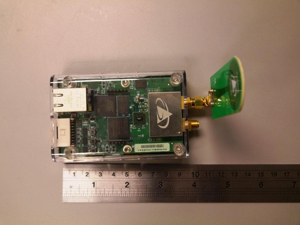
NUF-P440-A
Jan 26, 2016Ultra Wideband (UWB) radio transceiver
Equipment Class
UWB - Ultra Wideband Transmitter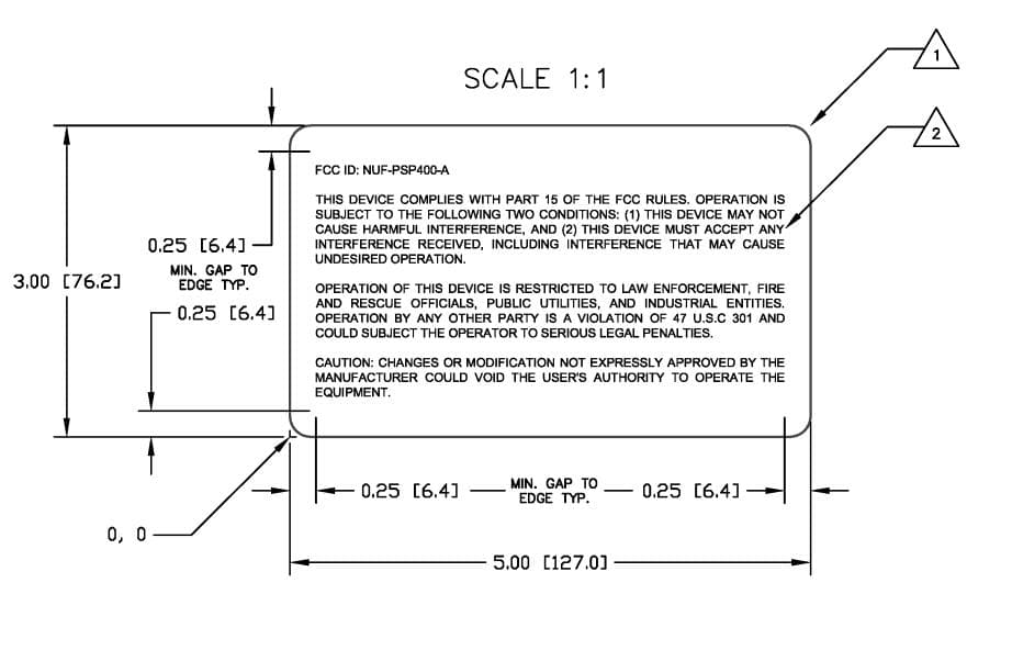
NUF-PSP400-A
Dec 21, 2014UWB Radar Surveillance System
Equipment Class
UWB - Ultra Wideband Transmitter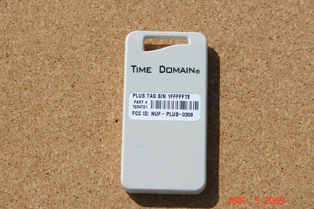
NUF-PLUS-0309
Apr 19, 2009PLUS Name Tag
Equipment Class
WBT - Wideband Transmitter
NUF-P350-1006
Apr 23, 2007THE PULSON P350 IS AN ACTIVE RFID SYSTEM (EAR99)
Equipment Class
WBT - Wideband Transmitter