NUF-P440-AUltra Wideband (UWB) radio transceiver
Humatics Corporation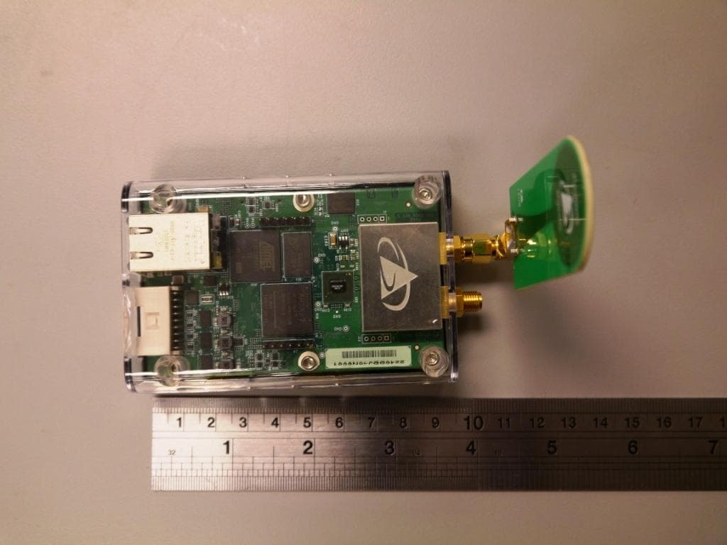
Click to zoom
Application Details
- Equipment Class
- UWB - Ultra Wideband Transmitter
- Date of Grant
- Jan 26, 2016
- Application Purpose
- Original Equipment
- Date of Application
- Jan 19, 2016
- Equipment Note
- Ultra Wideband (UWB) radio transceiver
- Frequency Range
- 3272.00000000 - 5014.00000000
- Company
- Humatics Corporation
- Country
- United States
Documents & Files
Document Text
Text extracted from the exhibit documents filed with the FCC. Open a document above to read the original.
Users Manual
Data Sheet / User Manual PulsON ® 440 320-0317A Dec 2015 DRAFT TIME DOMAIN ® Cummings Research Park 4955 Corporate Drive Suite 101 Huntsville, AL 35805 USA http://www.timedomain.com Tel: +1 256.922.9229 +1 888.826.8378 Fax: +1.256.922.0387 2 DRAFT P440 Data Sheet / User Guide Copyright All rights reserved. Time Domain ® 2001-2015. All rights reserved. Trademarks Time Domain ® , PulsON ® , and “PulsON Triangle” logo are registered trademarks of Time Domain. Microsoft ® and Windows Vista ® , Windows 7 ® , Windows 8®, and Windows 10® are registered trademarks of Microsoft Corporation. MATLAB® is a registered trademark of MathWorks, Inc. Any trademarks, trade names, service marks or service names owned or registered by any other company and used in this manual are the property of its respective company. Rights Rights to use this documentation are set forth in the PulsON Products Terms and Conditions of Sale. Document Information Time Domain reserves the right to change product specifications without notice. Any changes to the functionality or specifications will be issued as specific errata sheets or will be incorporated in new versions of this document. The latest version of this document and future documents can be found on the Time Domain website. The name/number and date of this document can be found on the left side of the cover page. Regulatory Approvals The P440, as supplied by Time Domain, has not yet been certified for use in any particular geographic region by the appropriate regulatory body governing radio emissions in that region. However, other members of the P400 series of devices have received such certification for use in the United States and the P440 is currently in the process of being tested for certification in the US. This certification is expected to be received later in 2015. This will be followed by a similar effort in Europe in 2016. All final products developed by the user which incorporate the P440 must be approved by the relevant authority governing radio emissions for the target market country(s). The User bears all responsibility for obtaining such approval(s). P440 Data Sheet / User Guide DRAFT 3 Table of Contents 1 SUMMARY ................................................................................................................... 5 2 P440 SOFTWARE ....................................................................................................... 7 2.1 P440 Embedded Software ....................................................................................................... 7 2.2 Application Programming Interfaces (APIs) ......................................................................... 7 2.3 Graphical User Interfaces (GUIs) and Sample Code ............................................................ 8 2.4 APIs and GUIs as Development Tools .................................................................................. 9 2.4.1 Ranging Measurement with RangeNet ................................................................................................ 9 2.4.2 Networking with RangeNet ................................................................................................................ 13 2.4.3 Monostatic Radar with MRM RET ...................................................................................................... 16 2.4.4 Bistatic Radar and Propagation with CAT (Channel Analysis Tool) ................................................... 19 2.5 Networking: RangeNet vs. RangeNet Lite ........................................................................... 20 2.6 Software Support ................................................................................................................... 21 3 HARDWARE BLOCK DIAGRAM ................................................................................22 4 ELECTRICAL INTERFACES ......................................................................................24 4.1 Connecting to the P440 ......................................................................................................... 25 4.2 Connector Pinouts ................................................................................................................ 25 4.3 Powering and Grounding the Unit ....................................................................................... 29 4.3.1 Powering the P440 through the USB Power jack vs Locking & Mezzanine connectors ..................... 29 4.3.2 Reverse polarity protection ................................................................................................................ 29 4.3.3 Two means of powering the P440 ...................................................................................................... 29 4.3.4 Chassis Ground ................................................................................................................................. 30 4.3.5 Fused_Ground and Digital_Ground ................................................................................................... 30 4.3.6 P440 Power requirements ................................................................................................................. 30 4.4 Host to P440 Interface Options ............................................................................................ 31 4.4.1 USB 2.0 High Speed Device .............................................................................................................. 32 4.4.2 User Serial ......................................................................................................................................... 32 4.4.3 SPI ..................................................................................................................................................... 32 4.4.4 Ethernet and IP Addressing ............................................................................................................... 35 4.4.5 CAN ....................................…
Text truncated - open the document above for the full version.
Cover Letter(s)
SGS North America Inc. Consumer Testing Services 620 Old Peachtree Road NW, Suwanee GA 30024 t (770) 570-1800 f (770) 277-1240 www.us.sgs.com/cts Member of the SGS Group (SGS SA) Federal Communications Commission Authorization and Evaluation Division Confidentiality Request regarding application for certification of FCC ID: NUF-P440-A. Pursuant to Sections 0.457 and 0.459 of the Commission’s Rules, we hereby request confidential treatment of information accompanying this application as outlined below: Exhibit Type File Name Schematics P440_Schematic Block Diagrams P440_Blk Theory of Operation P440_OpDesc The above materials contain trade secrets and proprietary information not customarily released to the public. The public disclosure of these materials may be harmful to the applicant and provide unjustified benefits to its competitors. The applicant understands that pursuant to Section 0.457 of the Rules, disclosure of this application and all accompanying documentation will not be made before the date of the Grant for this application. Sincerely, David Schramm, EMC/RF/SAR/HAC Manager Agent for TDC Acquisition Holdings Inc.
External Photos
EXTERNAL PHOTOS FCC ID: NUF-P440-A 2 3 4 5 6 7 8
ID Label/Location Info
FCC ID Label Artwork Also found on page 58 of the Data Sheet – Users Guide
ID Label/Location Info
Fcc ID Label Location Also found on page 58 of the Data Sheet – Users Guide
Internal Photos
INTERNAL PHOTOS FCC ID: NUF-P440-A 2 3 4
Test Report
Test Report Number: 3910067 EMC01 Rev: 1 Time Domain Corporation / P440 Page: 1 of 34 Remarks: This report details the results of the testing carried out on one sample, the results contained in this test report do not relate to other samples of the same product. The manufacturer should ensure that all products in series production are in conformity with the product sample detailed in this report. This report may only be reproduced and distributed in full. If the product in this report is used in any configuration other than that detailed in the report, the manufacturer must ensure the new system complies with all relevant standards. Any mention of SGS International Electrical Approvals or Testing done by SGS International Electrical Approvals in connection with distribution or use of the product described in this report must be approved by SGS international Electrical Approvals in writing. EMC Test Report Project Number: 3910067 Report Number: 3910067EMC01 Revision Level: 1 Client: Time Domain Corporation Equipment Under Test: UWB transmitter Model Number: P440 FCC ID: NUF-P440-A Applicable Standards: FCC Part 15, Subpart F ANSI C63.10:2013 Report issued on: 19 January 2016 Test Result: Compliant Tested by: Fabian Nica, Senior Engineering Technician Reviewed by: David Schramm, EMC/RF/SAR/HAC Manager Test Report Number: 3910067 EMC01 Rev: 1 Time Domain Corporation / P440 Page: 2 of 34 SGS North America Inc. Consumer Testing Services 620 Old Peachtree Road NW, Suite 100, Suwanee, GA 30024 t (770) 570-1800 www.us.sgs.com/cts Member of the SGS Group (SGS SA TABLE OF CONTENTS 1 SUMMARY OF TEST RESULTS ..................................................................................................................................... 4 1.1 MODIFICATIONS REQUIRED TO COMPLIANCE .............................................................................................................. 4 2 GENERAL INFORMATION .............................................................................................................................................. 5 2.1 CLIENT INFORMATION ................................................................................................................................................... 5 2.2 TEST LABORATORY ...................................................................................................................................................... 5 2.3 GENERAL INFORMATION OF EUT ................................................................................................................................. 5 2.4 OPERATING MODES AND CONDITIONS ......................................................................................................................... 5 3 UWB BANDWIDTH REQUIREMENTS ........................................................................................................................... 6 3.1 TEST RESULT ............................................................................................................................................................... 6 3.2 TEST METHOD .............................................................................................................................................................. 6 3.3 TEST SITE ..................................................................................................................................................................... 6 3.4 TEST EQUIPMENT ......................................................................................................................................................... 6 3.5 TEST DATA.................................................................................................................................................................... 7 4 RADIATED EMISSIONS ABOVE 960 MHZ................................................................................................................... 8 4.1 TEST RESULT ............................................................................................................................................................... 8 4.2 TEST METHOD .............................................................................................................................................................. 8 4.3 TEST SITE ..................................................................................................................................................................... 9 4.4 TEST EQUIPMENT ......................................................................................................................................................... 9 4.5 TEST DATA.................................................................................................................................................................. 10 5 RADIATED EMISSIONS IN GPS RECEIVE BAND.................................................................................................... 17 5.1 TEST RESULT ............................................................................................................................................................. 17 5.2 TEST METHOD ............................................................................................................................................................ 17 5.3 TEST SITE ................................................................................................................................................................... 17 5.4 TEST EQUIPMENT ....................................................................................................................................................... 17 5.5 TEST DATA.................................................................................................................................................................. 18 6 PEAK POWER WITHIN A 50 MHZ BANDWIDTH ...........................................................................................…
Text truncated - open the document above for the full version.
Test Report
Ambient emissions scan EUT was removed from the chamber Noise spike are related to EMI receiver and Ethernet cable passing through the waveguide. R a dia t e d Emis s ions Ve rt ic a l Fre que nc y 960.00M3.10G -20.0 -10.0 0 10.0 20.0 30.0 40.0 50.0 60.0 70.0 80.0 Amplit ude dBuV/m Inf o: : : :C urre nt Time - 0 2 : 1 8 : 3 7 PM, Monda y , D e c e mbe r 0 7 , 2 0 1 5 1 5 .5 1 9 @ 0 .5 m TX O FF Lim it V er tical sweep R a dia t e d Emis s ions H oriz ont a l Fre que nc y 960.00M3.10G -20.0 -10.0 0 10.0 20.0 30.0 40.0 50.0 60.0 70.0 80.0 Amplit ude dBuV/m Inf o: : : :C urre nt Time - 0 2 : 1 8 : 3 6 PM, Monda y , D e c e mbe r 0 7 , 2 0 1 5 1 5 .5 1 9 @ 0 .5 m TX O FF Lim it H or izontal sweep H or izontal discr eet Layout of testing when cable lengths are critical for the measurement. Example here approximates the test position when testing at a 0.5 meter distance. DOORFilters E U T EMI Rx / Preamp Ethernet To EUT AC Power(s) (1) Ethernet To EMI Receiver through waveguide
Test Setup Photos
TEST SETUP PHOTOS FCC ID: NUF-P440-A 2 3 4 5 6
Contact Information
Applicant
Alan Petroff
Test Firm
SGS North America, Inc.David Schramm
Technical Specifications
| # | Rule Parts | Frequency Range | Power Output |
|---|---|---|---|
| 1 | 15F | 3.27 GHz - 5.01 GHz | - |
Other Applications from Humatics Corporation
NUF-C445-A
Feb 25, 2020Ultra wideband radio
Equipment Class
UWB - Ultra Wideband Transmitter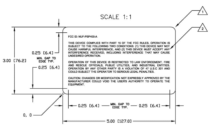
NUF-PSP400-A
Dec 21, 2014UWB Radar Surveillance System
Equipment Class
UWB - Ultra Wideband Transmitter
NUF-P412-A
Feb 03, 2013P412 Ultra Wideband radio transceiver
Equipment Class
UWB - Ultra Wideband Transmitter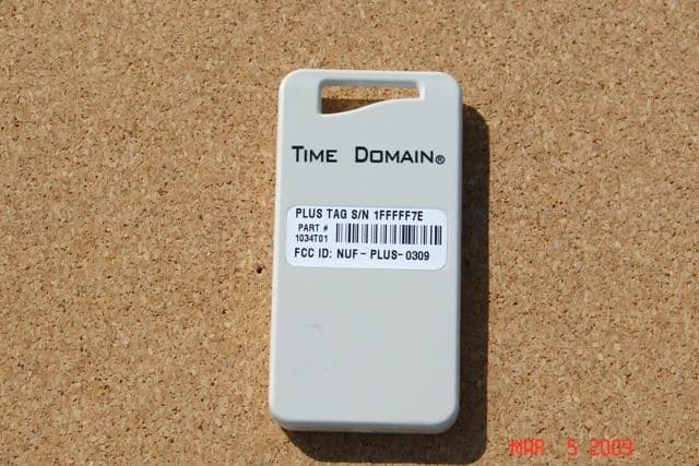
NUF-PLUS-0309
Apr 19, 2009PLUS Name Tag
Equipment Class
WBT - Wideband Transmitter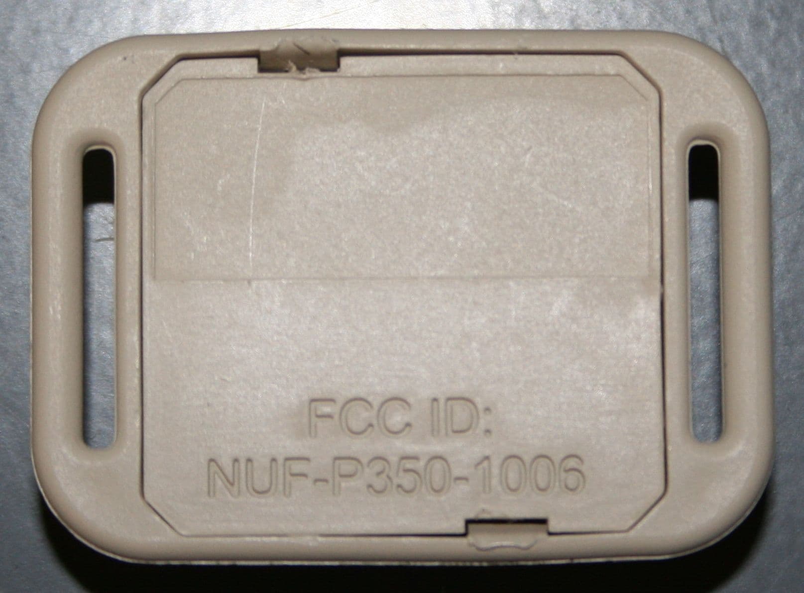
NUF-P350-1006
Apr 23, 2007THE PULSON P350 IS AN ACTIVE RFID SYSTEM (EAR99)
Equipment Class
WBT - Wideband Transmitter