NUF-PSP400-AUWB Radar Surveillance System
Humatics Corporation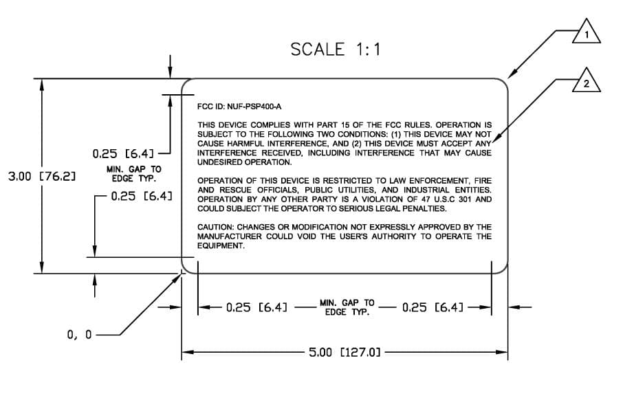
Click to zoom
Application Details
- Equipment Class
- UWB - Ultra Wideband Transmitter
- Date of Grant
- Dec 21, 2014
- Application Purpose
- Original Equipment
- Date of Application
- Dec 18, 2014
- Equipment Note
- UWB Radar Surveillance System
- Frequency Range
- 3082.00000000 - 4139.00000000
- Company
- Humatics Corporation
- Country
- United States
Documents & Files
Document Text
Text extracted from the exhibit documents filed with the FCC. Open a document above to read the original.
Users Manual
User’s Manual Ult r a wideband Per imet er Sur v eillanc e Pole Draft October 23, 2014 TIME DOMAIN ® Cummings Research Park 4955 Corporate Drive Suite 101 Huntsville, AL 35805 USA http://www.timedomain.com Tel: +1 256.922.9229 +1 888.826.8378 Fax: +1.256.922.0387 2 Ultra Wideband Perimeter Surveillance Pole / User’s Manual Copyright All rights reserved. Time Domain ® 2001-2014. All rights reserved. Trademarks Time Domain ® , PulsON ® , and “PulsON Triangle” logo are registered trademarks of Time Domain. Microsoft ® and Windows XP ®, Windows Vista ® , and Windows 7 ® are registered trademarks of Microsoft Corporation. Any trademarks, trade names, service marks or service names owned or registered by any other company and used in this manual are the property of its respective company. Rights Rights to use this documentation are set forth in the PulsON Products Terms and Conditions of Sale. Notice to Users Operation of this device is restricted to law enforcement, fire and rescue officials, public utilities, and industrial entities. Operation by any other part is a violation of 47 U.S.C 301 and could subject the operator to serious legal penalties. Per Title 47, Part 15, Subpart F, paragraph 15.511(2), the operation of imaging systems requires coordination as detailed in paragraph 15.525. Parties operating under the provisions of Title 47, Part 15, Subpart F, paragraph 15.511 must be eligible for licensing under the provisions of part 90. Changes or modifications not expressly approved by the manufacturer could void the user’s authority to operate the equipment Time Domain as manufacturer is in charge of all marketing. Any purchasers (non- government) by commercial clients will be informed of their responsibility under FCC rules by receiving a copy of Section 15.525 which requires them to co-ordinate their activities and inform the FCC at the following address preferable via certified mail. Frequency Coordination Branch, OET Federal Communications Commission 445 12th Street, SW Washington, D.C. 20554 Attn: UWB Coordination Ultra Wideband Perimeter Surveillance Pole / User’s Manual 3 Overview This document is a User’s Manual for the Time Domain Ultra Wideband (UWB) Perimeter Surveillance Pole (PSP400). The document is divided into the following sections. Section 1 System Introduction & Theory of Operation Section 2 Pole Overview Section 3 P400 Radar Section 4 Broadspec Antenna Section 5 FCC Compliance The user will note we have not included a Section on installation and system bringup. After reviewing Section 1 the reader will appreciate that the PSP400 is one element of an overall system that will be integrated with existing elements of an installations fixed infrastructure. For this reason each installation is unique; system turn-on and setup instructions will be developed in conjunction the receiving facility. 1 System Introduction & Theory of Operation This document addresses the Ultra Wideband (UWB) surveillance radar pole which is the sensor component of an integrated surveillance system. In order to introduce and provide operational context for the pole the overall system is discussed in this Section. 1.1 System Overview The UWB Surveillance System (USS) creates a virtual fence along or around the perimeter of an area to be protected. It consists of a staggered fence line of distributed short range radars contained in poles. These poles work together to detect, track, and distinguish between people and animals moving along or through the perimeter area. The ability to distinguish between different types of targets also known as Items Of Interest (IOIs) is often referred to as classification. Because the USS does not create a physical barrier it can be deployed in areas where an actual fence would be detrimental to the environment such as along a shore line or across a wildlife migratory path. UWB is the enabling technology that allows the USSUSS to offer the following capabilities: All weather, day/night operation High Probability of Detection coupled with a Low Probability of False Alarms Deployment in cluttered RF environments (near fences, buildings, moderate foliage) Classification/Identification Numerous agencies eligible for licensing under the provisions of part 90 have identified an unmet need for a security system with the above characteristics. 4 Ultra Wideband Perimeter Surveillance Pole / User’s Manual Figure 1 is a conceptual depiction of the USS. As suggested in the figure the USS can track and independently classify multiple people and animals using its system of radars. A server processes data from the radars and provides outputs to external users of the data. A network connects the radars to each other and the server. The lower level components that make up the poles, server, and network and the USS interfaces will be described in subsequent paragraphs. USS requires supporting infrastructure including power, a wired network, pole footings, and a central server. The cost of this infrastructure suggests USS will be deployed around high value assets or infrastructure typically found at many Government installations. USS • Array • Network • Server Tracks/Classifications/Notifications Figure 1 USS System Concept As illustrated in Figure 2 USS consists of a staggered line of poles, a wired network and a server. The server processes data from the poles and controls radar operation through the network. Pole Array Server Ethernet Hub Radar (3) AC/DC Converter Terminal Keyboard Monitor RAID Storage Software Ethernet Hubs CAT-5e/CAT-6 Cables Power Cables Software Pole Ethernet Hub Radar (3) AC/DC Converter Software Pole Ethernet Hub Radar (3) AC/DC Converter Software ... Network Figure 2 USS Hardware Components Ultra Wideband Perimeter Surveillance Pole / User’s Manual 5 The number of poles deployed at a given site depends on the length of the perimeter that requires monitoring. The poles are organized into groups of six poles referrred to as networking cells. As shown i…
Text truncated - open the document above for the full version.
Attestation Statements
www.timedomain.com 1.256.922.9229 phone 1.256.922.0387 fax Authority to Act as Agent Date: December 15, 2014 PCTEST Engineering Laboratory, Inc. is authorized to act on our behalf, until otherwise notified, for applications to the Federal Communications Commission (FCC). We certify that we are not subject to denial of federal benefits, that includes FCC benefits, pursuant to Section 5301 of the Anti-Drug Abuse Act of 1988, 21 U.S.C. 862. Further, no party, as defined in 47 CFR 1.2002 (b), to the application is subject to denial of federal benefits, that includes FCC benefits. Thank you, Agency Agreement Expiration Date: September 30, 2015 By: _________Rachel Reinhardt _________Rachel Reinhardt_______ (Signature) (Print name) Title: _____President and CEO_____ On behalf of: _TDC Acquisition Holdings dba Time Domain___ (Company Name) Telephone: ___256 990 8995 ___________
Cover Letter(s)
TDC Acquisition Holdings, Inc. Cummings Research Park 4955 Corporate Drive Suite 101 Huntsville, AL 35805 15 December 2014 Federal Communications Commission Authorization and Evaluation Division 7435 Oakland Mills Road, Columbia, MD 21046 RE: Request of Confidentiality for FCC ID: NUF-PSP400-A To Whom It May Concern: Pursuant to Sections 0.457 and 0.459 of the Commission’s Rules (CFR 47), and Section 552 (b) (4) of the Freedom of Information Act, TDC Acquisition Holdings, Inc. hereby requests confidentiality and treatment of certain information accompanying this application. The materials contain trade secrets and proprietary information not customarily released to the public. The public disclosure of these matters might be harmful to the Applicant and provide unjustified benefits to its competitors. We are also hereby request Short-Term Confidentiality for 180 days after the grant as outlined in Public Notice DA 04-1705. This provision will give TDC Acquisition Holdings, Inc. temporary confidentiality of commercially sensitive information prior to product release. The requested Permanent and Temporary Confidential exhibits are listed as follows: PERMANENT AND SHORT-TERM CONFIDENTIAL LIST Exhibit Description PERMANENT 1 Block Diagram 2 Operational Description/Theory of Operation 3 Schematics SHORT-TERM CONFIDENTIAL 4 External Photos 5 Internal Photos 6 Test-Setup Photos 7 User’s Manual The Applicant understands that pursuant to Rule 0.457, disclosure of this application and all accompanying documentations, where applicable, will not be made public before the date of the Grant for this application. Sincerely, Rachel Reinhardt Signature Rachel Reinhardt CEO TDC Acqusition Holdings, Inc.
External Photos
18 Ultra Wideband Perimeter Surveillance Pole / User’s Manual 5 FCC Compliance The PSP400 has been designed to be in compliance with the FCC regulations governing UWB Surveillance Systems (Part 15.511). In compliance with FCC requirements the label depicted in Figure 17 is affixed to the Base Plate Cover of each pole at the location shown in Figure 18. Fig. 16: Label with FCC ID number Label location Figure 18: PSP400 label location
Test Report
FCC ID: NUF-PSP400-A FCC Pt. 15F ULTRA WIDEBAND TEST REPORT (CERTIFICATION) Reviewed by: Quality Manager Test Report S/N: Test Dates: EUT Type: Page 1 of 36 0Y1411202135.NUF 11/17 - 11/18/2014 UWB Radar Surveillance System © 2014 PCTEST Engineering Laboratory, Inc. V 1.30 11/10/2014 Applicant Name: Date of Testing: TDC Acquisition Holdings Inc. 11/17 - 11/18/2014 4955 Corporate Dr NW Test Site/Location: Huntsville, AL 35805 PCTEST Lab, Columbia, MD, USA USA Test Report Serial No.: 0Y1411202135.NUF FCC ID: NUF-PSP400-A APPLICANT: TDC Acquisition Holdings Inc. Application Type: Certification Model: PSP400 EUT Type: UWB Radar Surveillance System Frequency Range: 3082 – 4139 MHz FCC Classification: Ultra Wideband (UWB) FCC Rule Part(s): Part 15, Subpart F (15.511, 15.521) Test Procedure(s): ANSI C63.10-2009, KDB 393764 This equipment has been shown to be capable of compliance with the applicable technical standards as indicated in the measurement report and was tested in accordance with the measurement procedures specified in ANSI C63.10-2009. Test results reported herein relate only to the item(s) tested. I attest to the accuracy of data. All measurements reported herein were performed by me or were made under my supervision and are correct to the best of my knowledge and belief. I assume full responsibility for the completeness of these measurements and vouch for the qualifications of all persons taking them. PCTEST ENGINEERING LABORATORY, INC. 7185 Oakland Mills Road, Columbia, MD 21046 USA Tel. 410.290.6652 / Fax 410.290.6654 http://www.pctestlab.com MEASUREMENT REPORT FCC PART 15F ULTRA WIDEBAND FCC ID: NUF-PSP400-A FCC Pt. 15F ULTRA WIDEBAND TEST REPORT (CERTIFICATION) Reviewed by: Quality Manager Test Report S/N: Test Dates: EUT Type: Page 2 of 36 0Y1411202135.NUF 11/17 - 11/18/2014 UWB Radar Surveillance System © 2014 PCTEST Engineering Laboratory, Inc. V 1.30 11/10/2014 TABLE OF CONTENTS FCC PART 15F MEASUREMENT REPORT ....................................................................................................... 3 1.0 INTRODUCTION ...................................................................................................................................... 4 1.1 SCOPE ........................................................................................................................................................... 4 1.2 PCTEST TEST LOCATION ............................................................................................................................ 4 2.0 PRODUCT INFORMATION ..................................................................................................................... 5 2.1 EQUIPMENT DESCRIPTION......................................................................................................................... 5 2.2 TEST CONFIGURATIONS ............................................................................................................................. 6 2.3 EMI SUPPRESSION DEVICE(S)/MODIFICATIONS ...................................................................................... 6 3.0 DESCRIPTION OF TEST ........................................................................................................................ 7 3.1 EVALUATION PROCEDURE ......................................................................................................................... 7 3.2 AC LINE CONDUCTED EMISSIONS ............................................................................................................. 7 3.3 RADIATED EMISSIONS ................................................................................................................................ 8 3.4 ENVIRONMENTAL CONDITIONS ................................................................................................................. 8 4.0 ANTENNA REQUIREMENTS .................................................................................................................. 9 5.0 TEST EQUIPMENT CALIBRATION DATA ............................................................................................ 10 6.0 TEST RESULTS .................................................................................................................................... 11 6.1 SUMMARY ................................................................................................................................................... 11 6.2 TIMING MEASUREMENTS ......................................................................................................................... 12 6.3 10DB BANDWIDTH MEASUREMENT ......................................................................................................... 14 6.4 PEAK POWER WITHIN 50MHZ BANDWIDTH ............................................................................................ 17 6.5 RADIATED EMISSIONS ABOVE 960MHZ .................................................................................................. 19 6.6 RADIATED EMISSIONS BELOW 960MHZ .................................................................................................. 26 6.7 LINE-CONDUCTED TEST DATA ................................................................................................................. 34 7.0 CONCLUSION ....................................................................................................................................... 36 FCC ID: NUF-PSP400-A FCC Pt. 15F ULTRA WIDEBAND TEST REPORT (CERTIFICATION) Reviewed by: Quality Manager Test Report S/N: Test Dates: EUT Type: Page 3 of 36 0Y1411202135.NUF 11/17 - 11/18/2014 UWB Radar Surveillance System © 2014 PCTEST Engineering Laboratory, Inc. V 1.30 11/10/2014 MEASUREMENT REPORT FCC Part 15F § 2.1033 General Information APPLICANT: TDC Acquisition Holdings Inc. APPLICANT ADDRESS: 4955 Corporate Dr NW Huntsville, AL 35805, USA TEST SITE: PCTEST ENGINEERING LABORATORY, INC. TEST SITE ADDRESS: 7185 Oakland MIlls Road, Columbia, MD …
Text truncated - open the document above for the full version.
Test Setup Photos
TDC Acquisition Holdings Inc. FCC ID: NUF-PSP400-A Model: PSP400 Test Set-Up Photos EUT Type: UWB Radar Surveillance System Page 1 of 4 © 2014 PCTEST Engineering Laboratory, Inc. V 1.30 11/10/2014 TEST SETUP PHOTOGRAPHS Figure 1. AC Line Conducted Test Setup TDC Acquisition Holdings Inc. FCC ID: NUF-PSP400-A Model: PSP400 Test Set-Up Photos EUT Type: UWB Radar Surveillance System Page 2 of 4 © 2014 PCTEST Engineering Laboratory, Inc. V 1.30 11/10/2014 Figure 2. Radiated Emissions Test Setup Below 960MHz (3 meter) TDC Acquisition Holdings Inc. FCC ID: NUF-PSP400-A Model: PSP400 Test Set-Up Photos EUT Type: UWB Radar Surveillance System Page 3 of 4 © 2014 PCTEST Engineering Laboratory, Inc. V 1.30 11/10/2014 Figure 3. Radiated Emissions Test Setup Above 960MHz (1 meter) TDC Acquisition Holdings Inc. FCC ID: NUF-PSP400-A Model: PSP400 Test Set-Up Photos EUT Type: UWB Radar Surveillance System Page 4 of 4 © 2014 PCTEST Engineering Laboratory, Inc. V 1.30 11/10/2014 Figure 4. Radiated Emissions Test Setup Above 18GHz (1 meter)
Contact Information
Applicant
Alan Petroff
Technical Contact
PCTEST Engineering Laboratory, Inc.Randy Ortanez
[email protected]410-290-6652
6660-B Dobbin Road · Columbia, Maryland · United States
Test Firm
PCTEST Engineering Laboratory, Inc.Randy Ortanez
Technical Specifications
| # | Rule Parts | Frequency Range | Power Output |
|---|---|---|---|
| 1 | 15F | 3.08 GHz - 4.14 GHz | - |
Other Applications from Humatics Corporation
NUF-C445-A
Feb 25, 2020Ultra wideband radio
Equipment Class
UWB - Ultra Wideband Transmitter
NUF-P440-A
Jan 26, 2016Ultra Wideband (UWB) radio transceiver
Equipment Class
UWB - Ultra Wideband Transmitter
NUF-P412-A
Feb 03, 2013P412 Ultra Wideband radio transceiver
Equipment Class
UWB - Ultra Wideband Transmitter
NUF-PLUS-0309
Apr 19, 2009PLUS Name Tag
Equipment Class
WBT - Wideband Transmitter
NUF-P350-1006
Apr 23, 2007THE PULSON P350 IS AN ACTIVE RFID SYSTEM (EAR99)
Equipment Class
WBT - Wideband Transmitter