NUF-C445-AUltra wideband radio
Humatics Corporation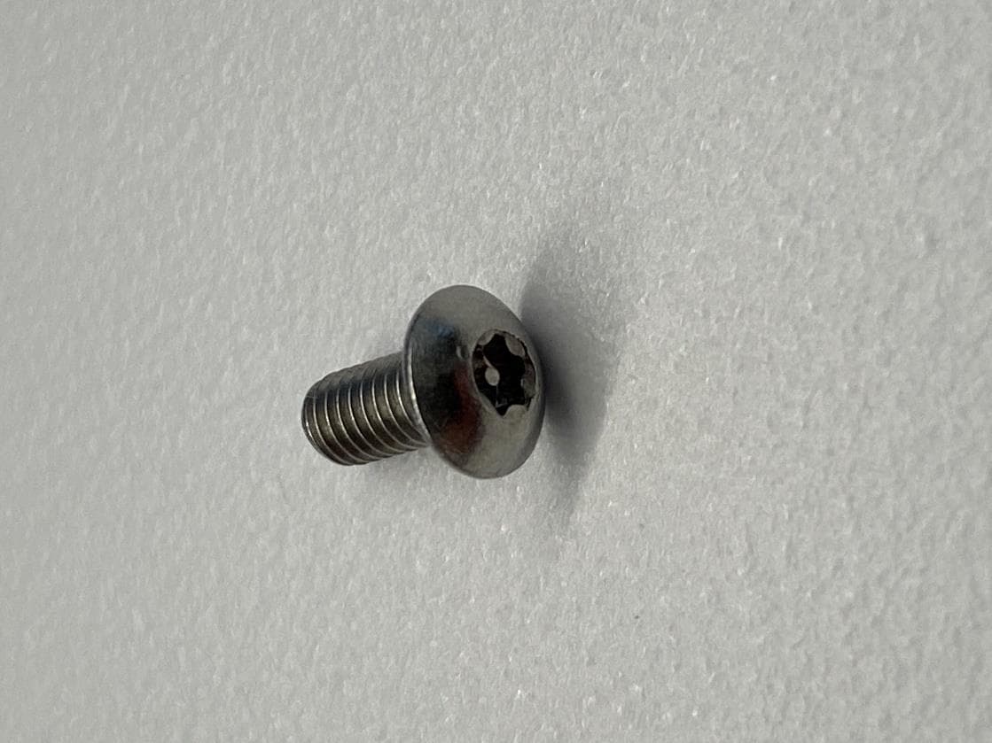
Click to zoom
Application Details
- Equipment Class
- UWB - Ultra Wideband Transmitter
- Date of Grant
- Feb 25, 2020
- Application Purpose
- Original Equipment
- Date of Application
- Feb 25, 2020
- Equipment Note
- Ultra wideband radio
- Frequency Range
- 3478.00000000 - 4916.00000000
- Company
- Humatics Corporation
- Country
- United States
Documents & Files
Document Text
Text extracted from the exhibit documents filed with the FCC. Open a document above to read the original.
Users Manual
C445 Beac on & Node Us er G uide 430-0001 Revision 6 December 2019 Humatics Headquarters 152 Grove Street, Suite 1500 Waltham, MA 02453 USA Humatics South 6767 Old Madison Pike Suite 410 Huntsville, Al 35806 DRAFT ver 6 Beacon User Guide For more information, please visit www.humatics.com. 2 Copyright All rights reserved. Humatics ® Corporation 2019. All rights reserved. Trademarks Humatics ® is a registered trademark of Humatics Corporation. Any trademarks, trade names, service marks or service names owned or registered by any other company and used in this manual are the property of its respective company. Rights Rights to use this documentation are set forth in the Humatics ® Products Terms and Conditions of Sale. Document Information Humatics reserves the right to change product specifications without notice. Any changes to the functionality or specifications will be issued as specific errata sheets or will be incorporated in new versions of this document. The latest version of this document and future documents can be found on the Humatics website. The name/number and date of this document can be found on the left side of the cover page. DRAFT ver 6 Beacon User Guide For more information, please visit www.humatics.com. 3 Table of Contents 1. Introduction ................................................................................................................ 4 2. System Block Diagrams ............................................................................................. 5 3. Mechanical .................................................................................................................. 6 4. Technical Specifications ............................................................................................ 8 5. Installation .................................................................................................................. 9 5.1 Software Setup Considerations ............................................................................. 9 5.2 Placement ................................................................................................................. 9 5.3 Mounting and Installation ..................................................................................... 10 5.4 Hookup .................................................................................................................... 14 6. Regulatory ..................................................................................................................14 7. Safety Certification ....................................................................................................16 8. Maintenance and Service ..........................................................................................16 DRAFT ver 6 Beacon User Guide For more information, please visit www.humatics.com. 4 1. Introduction The Humatics Beacon is part of a system for determining the location of mobile devices, such as robots or other vehicles, so that the devices can determine and report their location. This information will be used by the robots to navigate through a variety of environments, as for example, in factories, warehouses and outdoor storage or loading areas. The location information computed by the mobile devices could also be shared with supervisory computers so that managers and operators can monitor the location of the mobile devices. The system consists of two key components: equipment mounted on the robot and a fixed infrastructure of reference units. The reference units act much like lighthouses along the seashore, or like GPS satellites, providing reference information by which the robots can determine their positions. More precisely, the mobile devices use an UltraWideband (UWB) radio and a distance measurement technique called Two Way Time of Flight range measurement to determine the distance from it to a UWB radio mounted in each of several fixed reference locations. By knowing the position of each reference and by measuring the distance between mobile’s UWB radio and the UWB radio at each fixed reference, the mobile can calculate its position. Once the mobile has calculated its position it can report that value to the infrastructure units. Humatics refers to these infrastructure reference units as “Beacons”. Units installed on the mobile units are called “Nodes”. This document describes both the Beacons and Nodes. Both consist of a C445 UWB radio mounted in a metal enclosure and both support the same UWB ranging protocols. They differ in that the software loaded on the Nodes is more sophisticated. Node software supports the localization function and other high-level functions as well. The units are provided with two input connectors. The primary connector supports Power Over Ethernet. If no Ethernet is available, then DC power can be provided through a secondary connector. The units can be visually distinguished by the color of their radomes and by the part number prominently displayed on the identifying label. Beacons have a yellow radome and Nodes have gray ones. The units are rated for operation in environments that require IP67. DRAFT ver 6 Beacon User Guide For more information, please visit www.humatics.com. 5 2. System Block Diagrams The block diagram in Figure 1 shows the major elements of a Beacon/Node and illustrates two different ways of connecting the device to power. Fig. 1: Block Diagram of a Beacon Notes: • Normally the units will be powered through either, but not both, the POE or AUX power cables. Precautions are in place on the C445 radio to ensure that concurrently connecting the POE and Aux power will be accomplished safely. • There are two indicating LEDs mounted on the enclosure. These LEDs are powered by the C445 Radio. One is a simple power on indicator. The second LED is a heartbeat signal which blinks at a fixed rate when the radio is operating normally. Failure to blink is an indication that the C445 has failed. DRAFT ver 6 Beacon User Gu…
Text truncated - open the document above for the full version.
External Photos
EXTERNAL PHOTOGRAPHS Applicant: HumaticsCorporation Model –Beacon-Node FCC ID: NUF-C445-A 2 FRONT VIEW 3 REAR VIEW 4 LABEL SIDE 5 RIGHT SIDE 6 TOP SIDE 7 NODE COVER –SCREW TYPE 8 BOTTOM SIDE 9 BOTTOM SIDE -PORTS WWW.SGS.COM © SGS Group Management SA – 2016 – All rights reserved - SGS is a registered trademark of SGS Group Management SA
External Photos
NODE COVER SECURITY SCREW Applicant: HumaticsCorporation Model –Beacon-Node FCC ID: NUF-C445-A 2 TOP VIEW 3 TOP VIEW –CLOSE-UP 4 M3 SECURITY SCREW WWW.SGS.COM © SGS Group Management SA – 2016 – All rights reserved - SGS is a registered trademark of SGS Group Management SA
ID Label/Location Info
LABEL PLACEMENT Applicant: HumaticsCorporation Model –Beacon-Node FCC ID: NUF-C445-A 2 FRONT VIEW 3 LABEL LOCATION WWW.SGS.COM © SGS Group Management SA – 2016 – All rights reserved - SGS is a registered trademark of SGS Group Management SA
Internal Photos
INTERNAL PHOTOGRAPHS Applicant: HumaticsCorporation Model –Beacon-Mode FCC ID: NUF-C445-A 2 TOP COVER REMOVED 3 ANTENNA 4 MALE SMA ANTENNA 5 PCBINSTALLED IN HOUSING 6 PCB_TOPSIDE 7 PCB_UNDERSHIELD 8 FEMALE SMA ANTENNA JACK WWW.SGS.COM © SGS Group Management SA – 2016 – All rights reserved - SGS is a registered trademark of SGS Group Management SA
Test Report
Test Report Number: 4533138EMC01 Rev: 0 Humatics Corporation / Beacon-Node Page: 1 of 52 Remarks: This report details the results of the testing carried out on one sample, the results contained in this test report do not relate to other samples of the same product. The manufacturer should ensure that all products in series production are in conformity with the product sample detailed in this report. This report may only be reproduced and distributed in full. If the product in this report is used in any configuration other than that detailed in the report, the manufacturer must ensure the new system complies with all relevant standards. Any mention of SGS International Electrical Approvals or Testing done by SGS International Electrical Approvals in connection with distribution or use of the product described in this report must be approved by SGS international Electrical Approvals in writing. EMC Test Report Project Number: 4533138 Proposal Number: 9655 Report Number: 4533138EMC01 Revision Level: 0 Client: Humatics Corporation Equipment Under Test: UWB Radio Model Name: Beacon-Node Model Number: Beacon – 200-00064 Node – 200-00063 FCC ID: NUF- C445-A Applicable Standards: FCC Part 15, Subpart F ANSI C63.10:2013 Report issued on: 7 February 2020 Test Result: Compliant Tested by: Brandon Osborn, Project Engineer Reviewed by: David Schramm, Operations Manager Test Report Number: 4533138EMC01 Rev: 0 Humatics Corporation / Beacon-Node Page: 2 of 52 SGS North America Inc. Consumer and Retail 620 Old Peachtree Road NW, Suite 100, Suwanee, GA 30024 t (770) 570-1800 www.sgs.com Member of the SGS Group (SGS SA) TABLE OF CONTENTS 1 SUMMARY OF TEST RESULTS ..................................................................................................................................... 4 1.1 MODIFICATIONS REQUIRED TO COMPLIANCE .............................................................................................................. 4 2 GENERAL INFORMATION .............................................................................................................................................. 5 2.1 CLIENT INFORMATION ................................................................................................................................................... 5 2.2 TEST LABORATORY ...................................................................................................................................................... 5 2.3 GENERAL INFORMATION OF EUT ................................................................................................................................. 5 2.4 OPERATING MODES AND CONDITIONS ......................................................................................................................... 5 2.5 SYSTEM CONFIGURATIONS .......................................................................................................................................... 5 2.6 SUPPORT EQUIPMENT .................................................................................................................................................. 6 2.7 CABLE LIST ................................................................................................................................................................... 6 3 UWB BANDWIDTH REQUIREMENTS ........................................................................................................................... 7 3.1 TEST RESULT ............................................................................................................................................................... 7 3.2 TEST METHOD .............................................................................................................................................................. 7 3.3 TEST SITE ..................................................................................................................................................................... 7 3.4 TEST EQUIPMENT ......................................................................................................................................................... 7 3.5 TEST DATA.................................................................................................................................................................... 8 4 RADIATED EMISSIONS ABOVE 960 MHZ................................................................................................................... 9 4.1 TEST RESULT ............................................................................................................................................................... 9 4.2 TEST METHOD .............................................................................................................................................................. 9 4.3 TEST SITE ..................................................................................................................................................................... 9 4.4 TEST EQUIPMENT ....................................................................................................................................................... 10 4.5 TEST DATA – HORIZONTAL......................................................................................................................................... 11 4.6 TEST DATA – VERTICAL.............................................................................................................................................. 20 5 RADIATED EMISSIONS IN GPS RECEIVE BAND.................................................................................................... 29 5.1 TEST RESULT ............................................................................................................................................................. 29 5.2 TEST METHOD ...................................................................................................…
Text truncated - open the document above for the full version.
Test Setup Photos
TEST SETUP PHOTOGRAPHS Applicant: HumaticsCorporation Model –Beacon-Node FCC ID: NUF-C445-A 2 0.009-30 MHZ –RADIATED TEST SETUP 3 30-1000 MHZ -FRONT VIEW 4 30-1000 MHZ –REAR VIEW 5 1-18 GHZ TEST SETUP PHOTOGRAPHS 6 1-18 GHZ TEST SETUP PHOTOGRAPHS 7 ABOVE 18 GHZ TEST SETUP PHOTOGRAPH 8 CONDUCTED TEST SETUP PHOTOGRAPH WWW.SGS.COM © SGS Group Management SA – 2016 – All rights reserved - SGS is a registered trademark of SGS Group Management SA
Contact Information
Applicant
Alan Petroff
Technical Contact
SGS North AmericaBrandon Clark
[email protected]7705701800
620 Old Peachtree Rd NW · Suwanee, Georgia · United States
Non-Technical Contact
SGS North AmericaBrandon Osborn
[email protected]7705701800
Test Firm
SGS North America, Inc.David Schramm
Technical Specifications
| # | Rule Parts | Frequency Range | Power Output |
|---|---|---|---|
| 1 | 15F | 3.48 GHz - 4.92 GHz | - |
Other Applications from Humatics Corporation
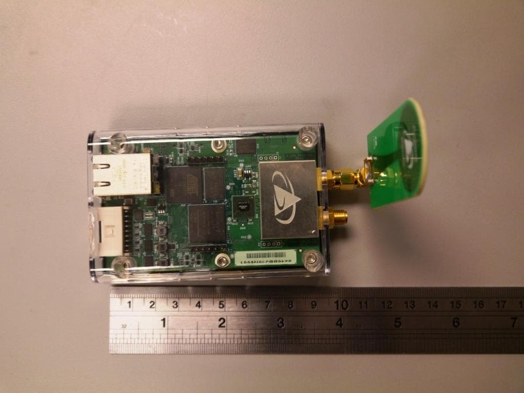
NUF-P440-A
Jan 26, 2016Ultra Wideband (UWB) radio transceiver
Equipment Class
UWB - Ultra Wideband Transmitter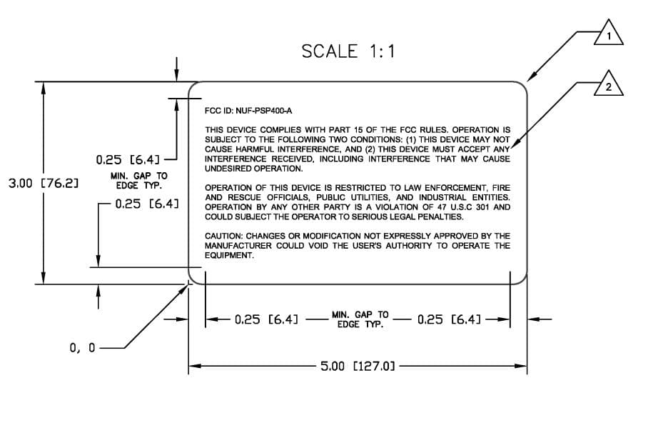
NUF-PSP400-A
Dec 21, 2014UWB Radar Surveillance System
Equipment Class
UWB - Ultra Wideband Transmitter
NUF-P412-A
Feb 03, 2013P412 Ultra Wideband radio transceiver
Equipment Class
UWB - Ultra Wideband Transmitter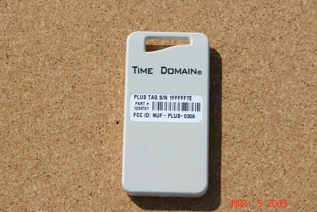
NUF-PLUS-0309
Apr 19, 2009PLUS Name Tag
Equipment Class
WBT - Wideband Transmitter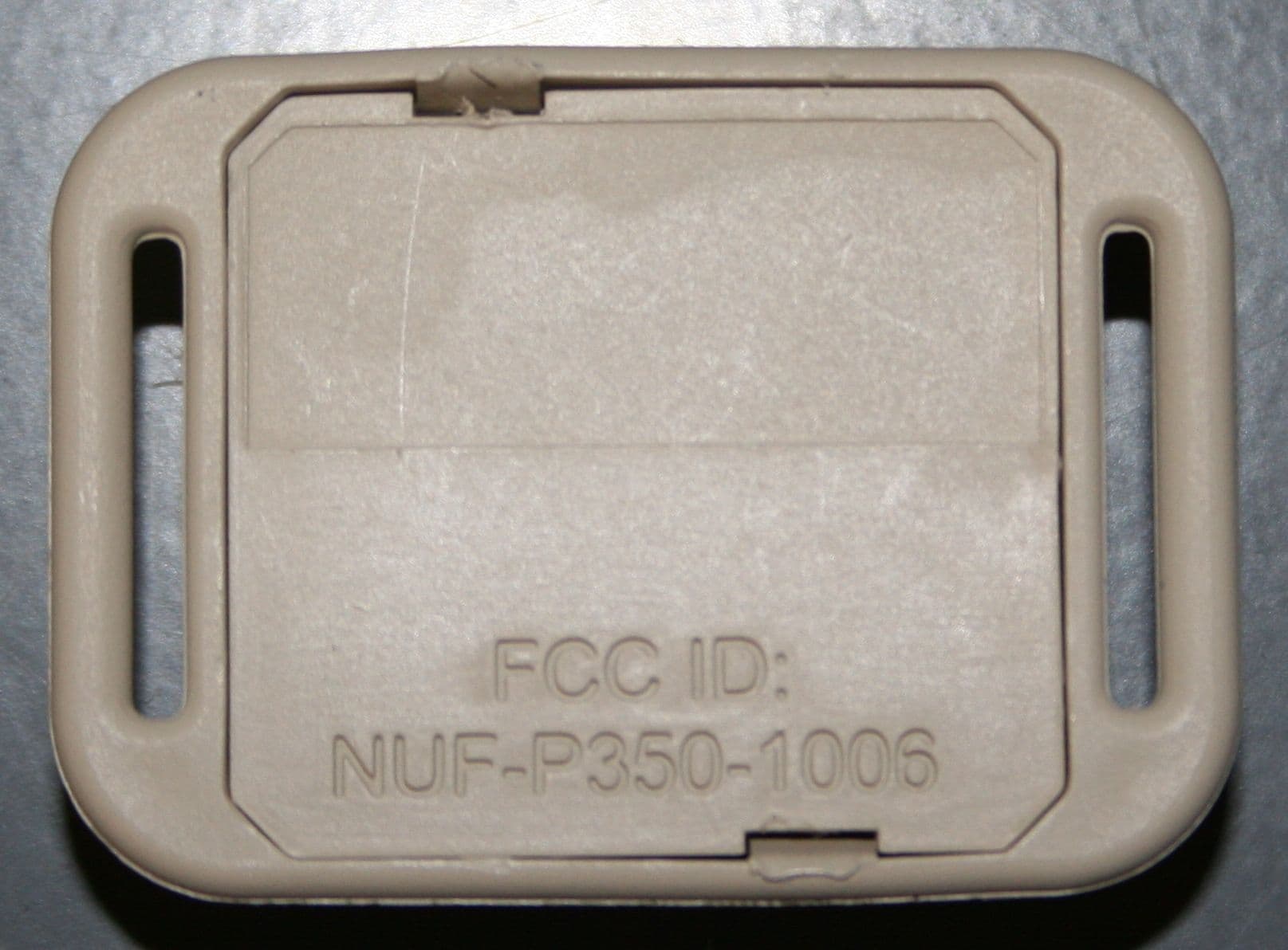
NUF-P350-1006
Apr 23, 2007THE PULSON P350 IS AN ACTIVE RFID SYSTEM (EAR99)
Equipment Class
WBT - Wideband Transmitter