NUF-200SGT-0702UWB Signal Generator / Transmitter
Humatics Corporation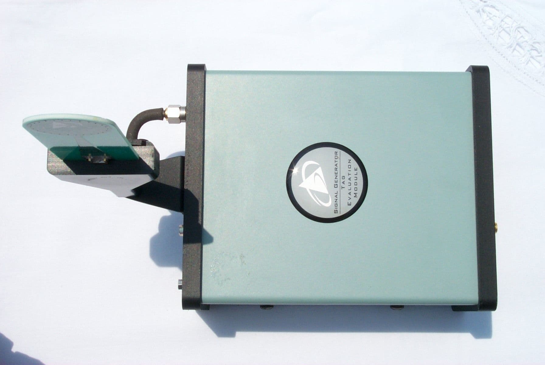
Click to zoom
Application Details
- Equipment Class
- UWB - Ultra Wideband Transmitter
- Date of Grant
- Oct 10, 2002
- Application Purpose
- Original Equipment
- Date of Application
- Jul 28, 2002
- Equipment Note
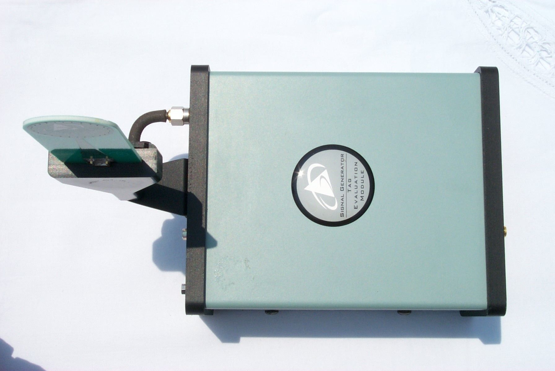
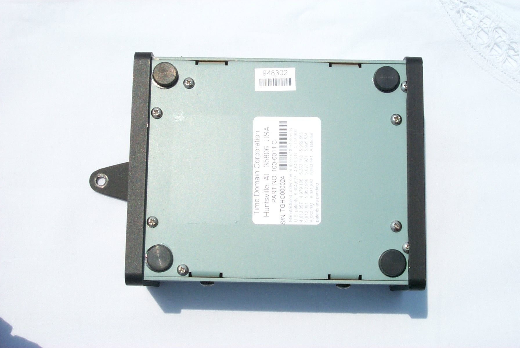
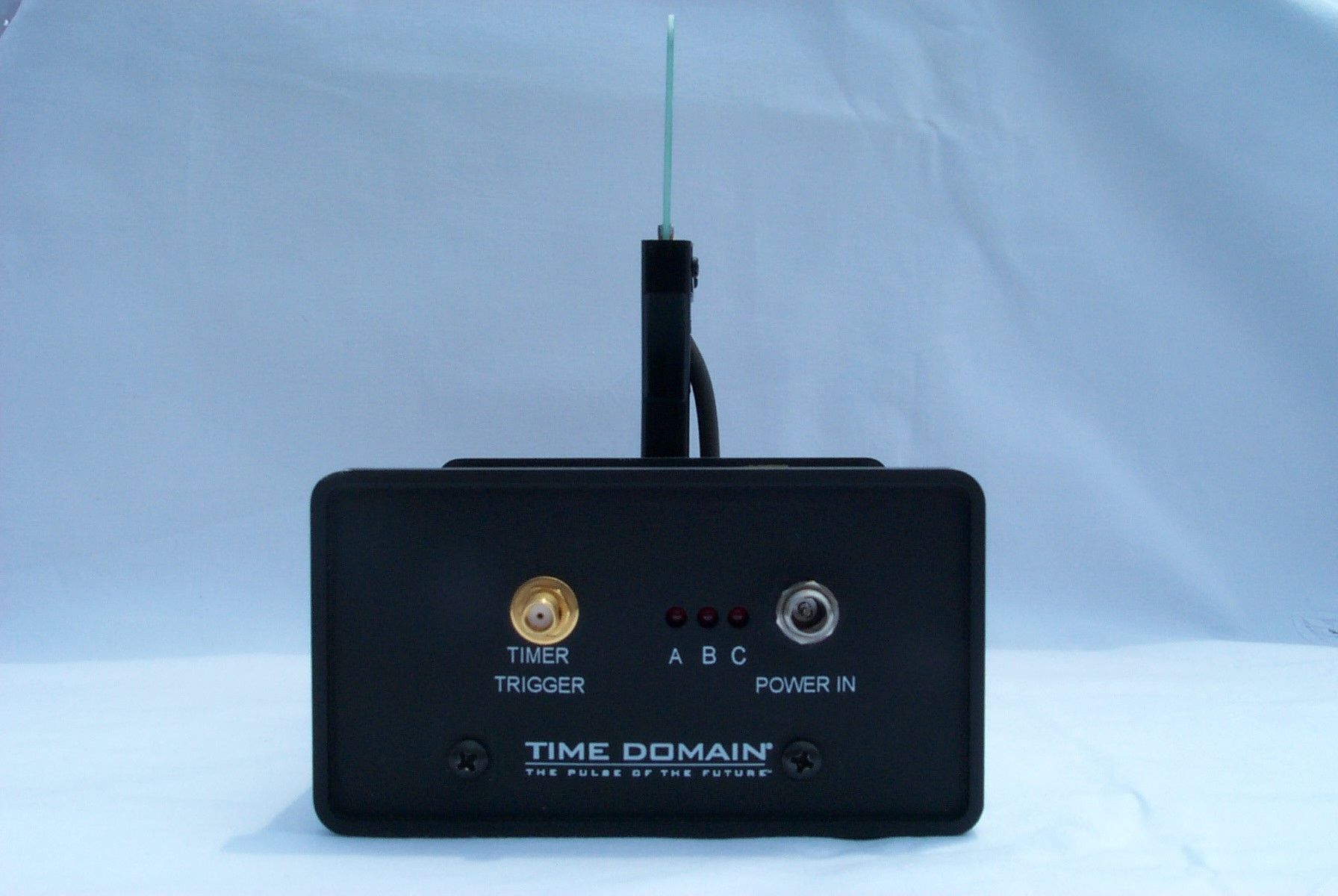
- UWB Signal Generator / Transmitter
- Frequency Range
- 3420.00000000 - 6950.00000000
- Company
- Humatics Corporation
- Country
- United States
Documents & Files
Document Text
Text extracted from the exhibit documents filed with the FCC. Open a document above to read the original.
Users Manual
COMPANY CONFIDENTIAL AND PROPRIETARY User Manual for the Signal Generator/Tag Time Domain Corporation Cummings Research Park 7057 Old Madison Pike Huntsville, AL 35806 USA http://www.timedomain.com Tel: 256.922.9229 888.826.8378 Fax: 256.922.0387 P200-320-0030C-FCC June 2002 2 COMPANY CONFIDENTIAL AND PROPRIETARY Copyright © 2001-2002 Time Domain Corporation. All rights reserved. Trademarks Time Domain ® and PulsON ® are registered trademarks of Time Domain Corporation. Ethernet ® is a registered trademark of Xerox Corpora- tion. Microsoft ® and Windows NT ® are registered trademarks of Microsoft Corporation. Xilinx ® is a registered trademark of Xilinx, Incorpo- rated. PulsON ® Technology Program ™ and PulsON 200 ™ are trademarks of Time Domain Corporation. MultiLINX ™ is a trademark of Xilinx, Incorporated. Any trademarks, trade names, service marks or service names owned or registered by any other company and used in this manual are the property of its respective company. Rights Rights to use this documentation are set forth in the License Agreement accompanying the Signal Generator/Tag. Regulatory Notice U.S. operation: • This device complies with Part 15 of the FCC Rules. Operation is subject to the following two conditions: (1) this device may not cause harmful interference, and (2) this device must accept any interference received, including interference that may cause undesired operation. • This device may only be operated indoors. Operation outdoors is in violation of 47 U.S.C. 301and could subject the operator to serious legal penalties. • FCC ID: NUF -200SGT-0702 •Please consult with Time Domain Corp. if you have any questions, prior to use. Non-U.S. Operation: PulsON ® technology has not been authorized for use or commercial exploitation under the regulations of any non-U.S. government agency. Please confer with your government’s regulatory agency to obtain proper authorizations. Customer Support Web:http://www.pulsondevelopers.com E-mail:[email protected] Telephone:+1 256.428.6333 Fax:+1 256.428.6622 Nondisclosure Provisions This manual contains Time Domain Corporation’s Confidential and Proprietary Information. Members of the PulsON ™ Developers Program and PulsON Technology Program are reminded of their obligations to protect TDC Confidential and Proprietary Information. II COMPANY CONFIDENTIAL AND PROPRIETARY Contents Nondisclosure Provisions...............................................................................................2 Overview............................................................................................................5 Getting Started...................................................................................................7 Unpacking & Initial Setup................................................................................................7 Installing Signal Generator Software..............................................................................8 System Checkout............................................................................................................8 Operating the Signal Generator/Tag................................................................11 Connecting the Host PC to the Signal Generator/Tag..................................................11 Software Controls.........................................................................................................12 Tag Information Section...........................................................................................12 Real-Time Clock......................................................................................................12 Controlling the Type & Frequency of Transmissions....................................................13 Transmission Modes.....................................................................................................13 Test Modes..............................................................................................................13 TAG Modes..............................................................................................................14 Configuring the Packet Repetition Cycle.....................................................................15 Packet Format Display..................................................................................................16 Packet Components................................................................................................16 Controlling Acquisition and Data Packet Components..................................................17 Other readouts and controls....................................................................................17 Scan Data Settings..................................................................................................18 Mode Selection........................................................................................................18 Default Button..........................................................................................................18 Acquisition Settings.................................................................................................18 TX Data Controls.....................................................................................................19 Master Reset Function............................................................................................21 Disconnecting from the Signal Generator/Tag.........................................................21 Taking Measurements......................................................................................23 Benchtop Cabled..........................................................................................................23 Recommended Test Instruments and Equivalents...................................................24 Benchtop Wireless........................................................................................................26 Wireless Pro…
Text truncated - open the document above for the full version.
Block Diagram
July 3, 2002Revision 1.0 Antenna Signal Generator/ TAG Computer Optional RS-232 Cable Power 125VAC Test Equipment Optional SMA Cable RS232 Antenna Out Timer Trigger Power In SG/TAG System Block Diagram
Block Diagram
July 5, 2002Revision 1.0 Antenna Digital Module FPGA Real-Time Clock Transmission Alarm Push Button Single Transmission Event/Cont. Continuous Transmission Sequencer Register Interface RS-232 PC/Smart Sensor Interface RAM Timer Interface Transmit Control FLASH Non-Volatile Data Storage Timer Coarse Delay Fine Delay Trigger Pulse Stretcher Trigger Pulse Output RF Module Pulse Driver Pulse Sharpening Pulse FlipperRF Filter SG/TAG Functional Block Diagram
Block Diagram
Digital Module July 3, 2002Revision 1.0 RF Module 19.2 MHz Oscillator A RF Filter Power In Timer Trigger Cont./EventRS232 Fire Pulser BC Custom Timer Chip FPGA FPGA EEPROM Real- Time Clo ck FL ASH RS 232 Driver Antenna Pulse Flipper Pulser Driver Power Supply 30 Power Supply JT AG JT AG Debug Port SG/TAG Physical Block Diagram
Cover Letter(s)
Time Domain Corporation Cummings Research Park 7057 Old Madison Pike Huntsville, Alabama 35806 Paul Withington VP/Senior Technologist [email protected] (256) 922 9229 www.time-domain.com 1.256.922.9229 phone 1.256.922-0387 fax Request for Confidential Treatment FCC ID No: NUF-200SGT-0702 Time Domain Corporation (TDC) requests that the FPGA detailed physical block diagram along with all schematics in exhibit three (RF and Digital boards), be withheld from public disclosure in accordance with Section 0.459 of the Commission’s Rules, 47 C.F.R. § 0.459 (2000), following grant of the application. In support of this request, TDC submits the following: (1) identification of the specific information for which confidential treatment is sought: The FPGA physical block diagram, Digital board schematics, and the RF board schematics in exhibit three, which are segregated from the non-confidential exhibits of the application, are those for which confidentiality is sought. (2) identification of the Commission proceeding in which the information was submitted or a description of the circumstances giving rise to the submission: The proceeding is that involving the application for equipment authorization (certification) under FCC ID No.: NUF-200SGT-0702 (3) explanation of the degree to which the information is commercial or financial, or contains a trade secret or is privileged: This material includes circuit diagrams and board layout information for the RF and Digital boards. As such, this material is treated as highly confidential business information (4) explanation of the degree to which the information concerns a service that is subject to competition: The material for which confidentiality is sought is employed in the design and manufacture of ultra-wideband communications and radar systems that is offered on a highly competitive basis. Customers for this equipment have a variety of competing sources of supply. TAG Certification Confidentiality Request July 19, 2002 Page 2 (5) explanation of how disclosure of the information could result in substantial competitive harm: Disclosure would, in effect, give away the fruits of the labors of eighty engineering personnel, who have designed the equipment and the manufacturing processes. Disclosure would also offer competitors additional unwarranted insight into the state of product development thereby allowing such competitors an advantage that would not be available to unless they were working with TDC and had a non-disclosure agreement with TDC. (6) identification of any measures taken by the submitting party to prevent unauthorized disclosure: The information for which confidential treatment is sought is kept confidential by TDC and not made available to third parties except pursuant to non-disclosure agreements. (7) identification of whether the information is available to the public and the extent of any previous disclosure of the information to third parties: To the knowledge of those preparing this application, the information has not been disclosed publicly heretofore. The protection sought is narrowly drawn and pertains to certain specific implementations of ultra-wideband technology. (8) justification of the period during which the submitting party asserts that material should not be available for public disclosure: This material should not be disclosed for at least five years. While improvements in design are made relatively frequently, disclosure of the design information would lead to insights into both designs and manufacturing techniques and could have an adverse competitive effect for many years to come. This equipment is designed for commercial, industrial, and governmental military research and development applications. As such, unlike most consumer equipment, it is expected to be used for more than five years in some cases. Moreover, this equipment may be used in some unclassified government research. As such, it is important that its design not be made available to unauthorized persons who might attempt to use knowledge of the design to compromise the applications for which the equipment will be employed. TAG Certification Confidentiality Request July 19, 2002 Page 3 (9) any other information that the party seeking confidential treatment believes may be useful in assessing whether its request for confidentiality should be granted: See item 8 above. Note that the equipment for which approval is being sought will be employed in applications that inherently carry a premium on security. Respectfully:_submitted electronically __ /s/ Paul Withington Vice-President Cummings Research Park 7057 Old Madison Pike Huntsville, AL 35806
Cover Letter(s)
Application Overview This application seeks certification of an ultra-wideband (UWB) device under the recently approved Part 15.517 (Technical Requirements for Indoor UWB Systems. The UWB device is a Time Modulated-Ultra Wideband™ (TM-UWB) transmitter. The corresponding TM-UWB receiver is not yet ready for certification. Until such time as the receiver is certified, customers will use test instrumentation, e.g., spectrum analyzers and high speed sampling oscilloscopes, to measure and view the transmitters’ emissions. The device is line powered. The antenna is carefully matched to the excitation waveform and is attached to the transmitter with a reverse polarity SMA connector. These connectors are difficult to obtain, which prevents the replacement of the antenna with an unapproved antenna. Intertek Testing Services in Atlanta, Georgia measured the device in accordance with the measurement procedures identified in the appendices of the FCC’s UWB Report and Order (FCC 02-48). Any deviations from those procedures have been annotated and explained.
Cover Letter(s)
To FCC Reviewing Engineer: A question has arisen as to the applicable rule sections for certain emissions from the UWB transmitter FCC ID:NUF-2000SGT-0702. Based on discussions, the emissions in question have a frequency of approximately 1228 and 1536 MHz. These emissions are related to operation of the digital circuits within the unit. As such they are not to be considered as intentional UWB emissions and are not radiated by the antenna of the UWB transmitter pursuant to Section 15.521(c). Section 15.231 (c) states the following: "If it can be clearly demonstrated that an emission from a UWB transmitter is due solely to emissions from digital circuitry contained within the transmitter and that the emission is not intended to be radiated from the transmitter’s antenna, the limits shown in Section 15.209 of this chapter shall apply to that emission rather than the limits specified in this section." Accordingly the correct limit to apply to the 1228 and 1536 MHz frequencies is the limit Specified in Section 15.209. Please refer to Section 5.3 of the submitted test report. This section describes the technique used to determine the appropriate classification of the emission radiated from the transmitter. Based on this technique, the above frequencies are subject to a limit of 500 uV/m measured at 3 meters using an average detector with a 1 MHz resolution bandwidth. Phil Inglis
Operational Description
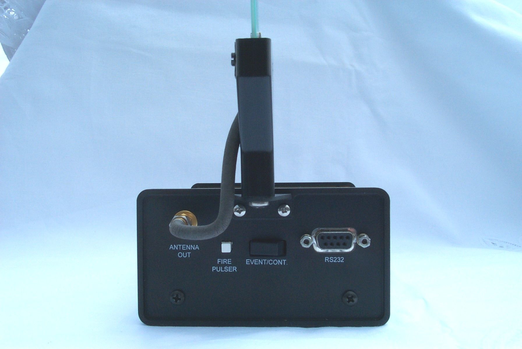
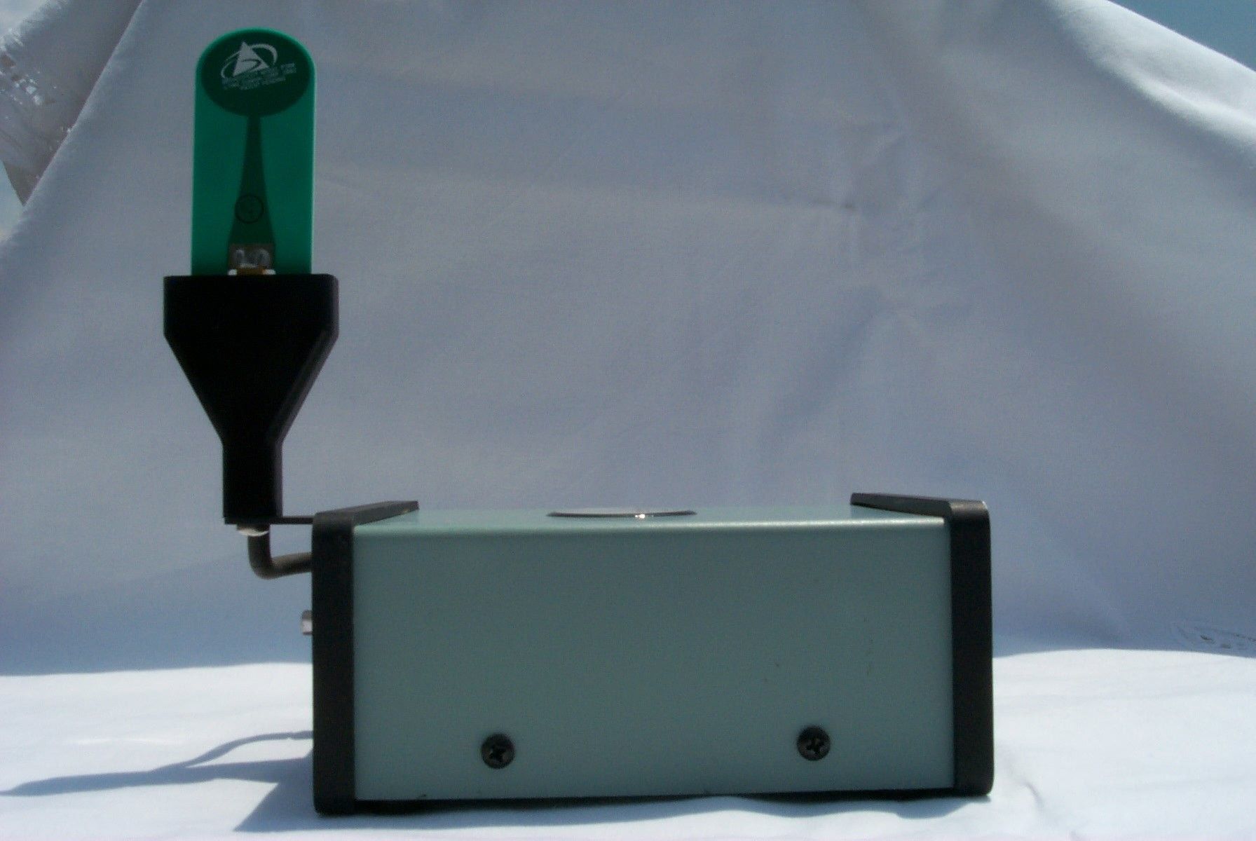
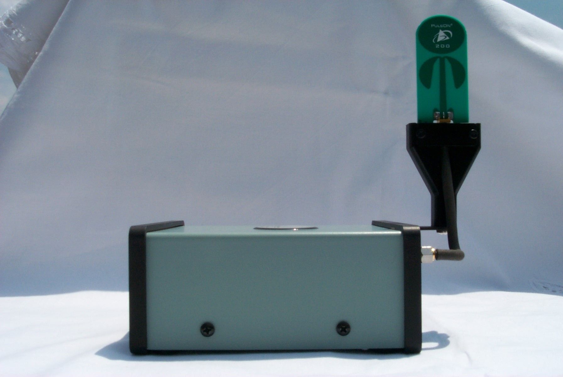
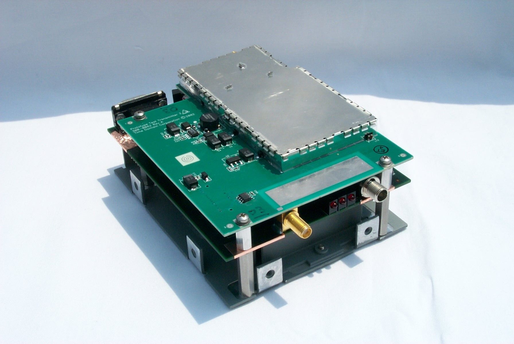
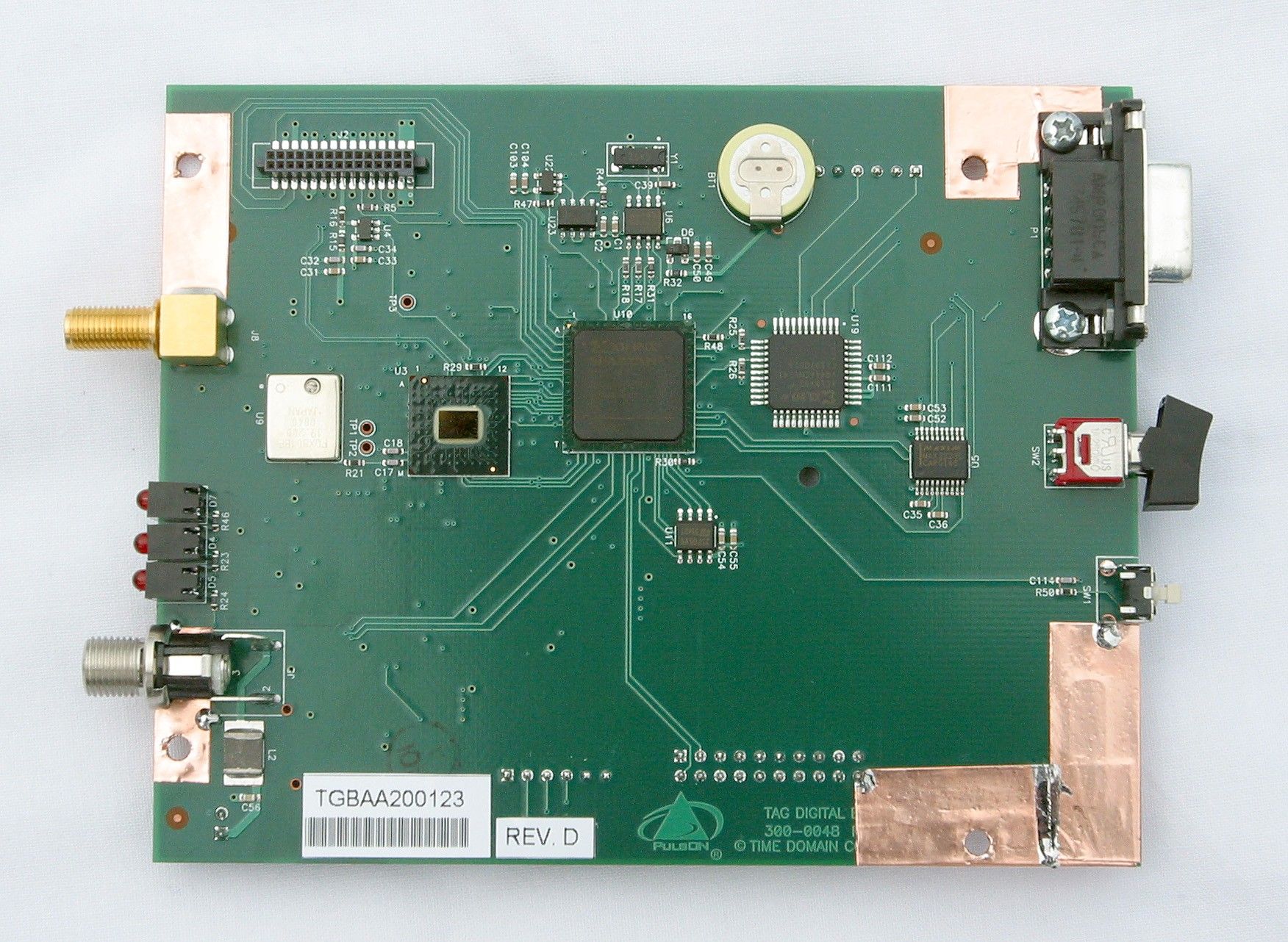
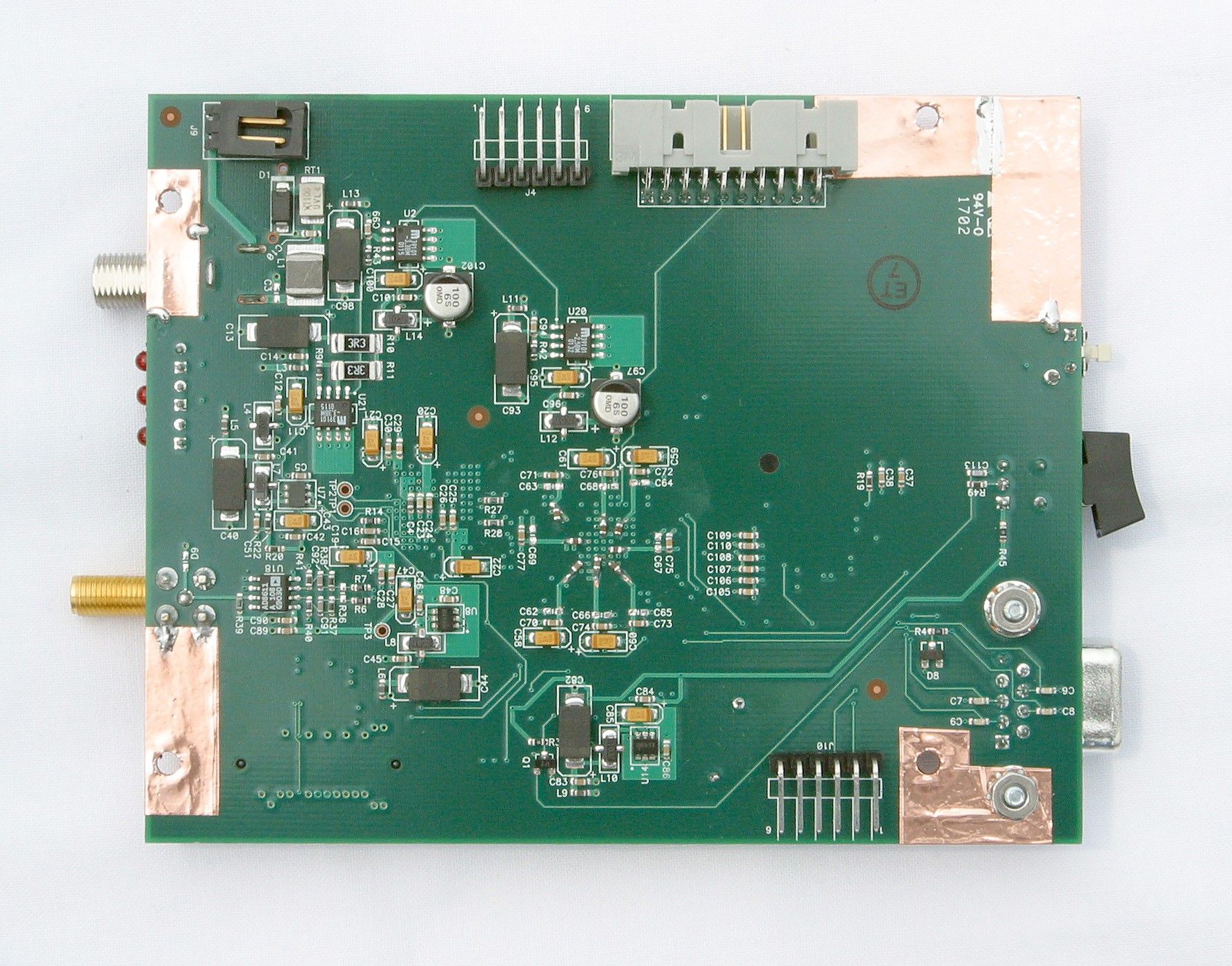
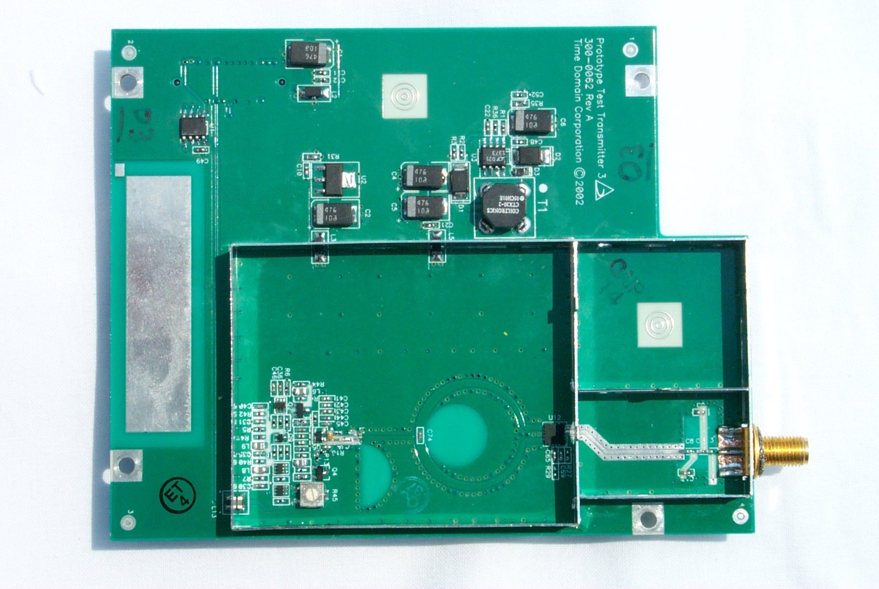
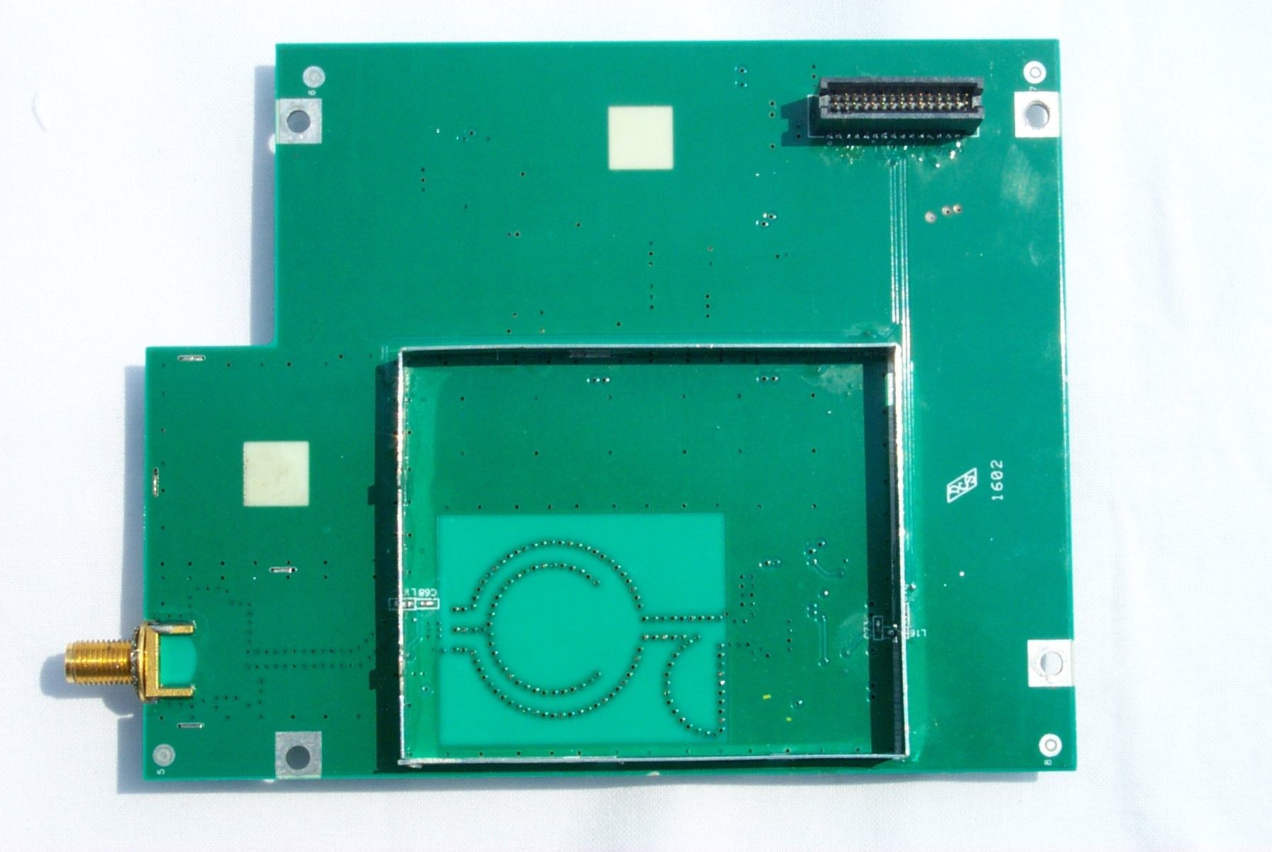
Product Description The Signal Generator/Tag (SG/T) is a transmit-only radio, with two distinct roles in the PulsON 200 ΤΜ equipment family. TDC product partners will initially use the Signal Generator capability as a means to evaluate UWB propagation and co-existence with other RF devices. The SG/T will be used with laboratory equipment such as oscilloscopes and spectrum analyzers to perform a number of experiments aimed at determining the most effective applications of UWB based performance and environmental factors. When paired with the PulsON 200 ΤΜ Evaluation Kit radio, the SG/T will be capable of acting as a communications and tracking Tag. In this application, the unit can be configured to pass data packets that support UWB ranging and positioning, communications or a fusion of both types of data. The Evaluation Kit radio will use key algorithms and PulsON 200 ΤΜ capabilities to “read” the tag and convert the packet into a usable form. The unit submitted for FCC certification has the capabilities of performing either of the intended purposes, however the tag function can only be realized as part of a system with the Evaluation Kit radio The SG/T consists of a digital module, an RF module, an antenna assembly and a housing. The digital board contains the PulsON 200 ΤΜ Timer Chip, which provides precise triggers to the RF board, a Field Programmable Gate Array (FPGA) containing the control logic for the SG/T functionality, various interfaces for data collection and power, and memory. The RF module creates the pulse that will be transmitted and “flips” them to allow data to be encoded. The antenna assembly couples the BroadSpec ΤΜ Model antenna with the reverse polarity SMA connector for use on the SG/T. The SG/T is set up for operation and controlled by software running on a host computer and communicating via the serial cable. Once configured using the host software, the SG/T can operate without being attached to the host PC in the configuration set and initialized prior to disconnecting. The software allows the user to define the mode of operation, type and structure of the transmission packets and the rate in which the packet is sent out (e.g. every 10 seconds or when commanded to by a device attached to the serial port). It will not allow the user to alter the fundamental UWB structure, nor can the user place the radio in a mode that spectrally violates the FCC regulations.
Operational Description
COMPANY CONFIDENTIAL AND PROPRIETARY User Manual for the Signal Generator/Tag Time Domain Corporation Cummings Research Park 7057 Old Madison Pike Huntsville, AL 35806 USA http://www.timedomain.com Tel: 256.922.9229 888.826.8378 Fax: 256.922.0387 P200-320-0030C-FCC June 2002 2 COMPANY CONFIDENTIAL AND PROPRIETARY Copyright © 2001-2002 Time Domain Corporation. All rights reserved. Trademarks Time Domain ® and PulsON ® are registered trademarks of Time Domain Corporation. Ethernet ® is a registered trademark of Xerox Corpora- tion. Microsoft ® and Windows NT ® are registered trademarks of Microsoft Corporation. Xilinx ® is a registered trademark of Xilinx, Incorpo- rated. PulsON ® Technology Program ™ and PulsON 200 ™ are trademarks of Time Domain Corporation. MultiLINX ™ is a trademark of Xilinx, Incorporated. Any trademarks, trade names, service marks or service names owned or registered by any other company and used in this manual are the property of its respective company. Rights Rights to use this documentation are set forth in the License Agreement accompanying the Signal Generator/Tag. Regulatory Notice U.S. operation: • This device complies with Part 15 of the FCC Rules. Operation is subject to the following two conditions: (1) this device may not cause harmful interference, and (2) this device must accept any interference received, including interference that may cause undesired operation. • This device may only be operated indoors. Operation outdoors is in violation of 47 U.S.C. 301and could subject the operator to serious legal penalties. • FCC ID: NUF -200SGT-0702 •Please consult with Time Domain Corp. if you have any questions, prior to use. Non-U.S. Operation: PulsON ® technology has not been authorized for use or commercial exploitation under the regulations of any non-U.S. government agency. Please confer with your government’s regulatory agency to obtain proper authorizations. Customer Support Web:http://www.pulsondevelopers.com E-mail:[email protected] Telephone:+1 256.428.6333 Fax:+1 256.428.6622 Nondisclosure Provisions This manual contains Time Domain Corporation’s Confidential and Proprietary Information. Members of the PulsON ™ Developers Program and PulsON Technology Program are reminded of their obligations to protect TDC Confidential and Proprietary Information. II COMPANY CONFIDENTIAL AND PROPRIETARY Contents Nondisclosure Provisions...............................................................................................2 Overview............................................................................................................5 Getting Started...................................................................................................7 Unpacking & Initial Setup................................................................................................7 Installing Signal Generator Software..............................................................................8 System Checkout............................................................................................................8 Operating the Signal Generator/Tag................................................................11 Connecting the Host PC to the Signal Generator/Tag..................................................11 Software Controls.........................................................................................................12 Tag Information Section...........................................................................................12 Real-Time Clock......................................................................................................12 Controlling the Type & Frequency of Transmissions....................................................13 Transmission Modes.....................................................................................................13 Test Modes..............................................................................................................13 TAG Modes..............................................................................................................14 Configuring the Packet Repetition Cycle.....................................................................15 Packet Format Display..................................................................................................16 Packet Components................................................................................................16 Controlling Acquisition and Data Packet Components..................................................17 Other readouts and controls....................................................................................17 Scan Data Settings..................................................................................................18 Mode Selection........................................................................................................18 Default Button..........................................................................................................18 Acquisition Settings.................................................................................................18 TX Data Controls.....................................................................................................19 Master Reset Function............................................................................................21 Disconnecting from the Signal Generator/Tag.........................................................21 Taking Measurements......................................................................................23 Benchtop Cabled..........................................................................................................23 Recommended Test Instruments and Equivalents...................................................24 Benchtop Wireless........................................................................................................26 Wireless Pro…
Text truncated - open the document above for the full version.
Parts List/Tune Up Info
TIME DOMAIN CORPORATION DO NOT SCALE DRAWING APPROVALS D1 DATE TIME DOMAIN THE PULSE OF THE FUTURE Huntsville, AL OF 100-0011 10A-0011 C UNIT ASSEMBLY, SIGNAL GENERATOR/TAG 1 1 ~ J ROBINSON 02-01-02 10A-0011C SIGNAL GEN_TAG.DWG Huntsville, AL 35806 USA Time Domain Corporation
Test Report
EMC Report for Time Domain Corporation on the TAG File: 0227351uwb.doc Page 1 of 25 TEST REPORT Report Number: 0227351uwb.doc Project Number: 3027351 July 19, 2002 Evaluation of the TAG Model Number: 100-0011C to CFR 47 Part 15, Subpart F For Time Domain Corporation Test Performed by: Test Authorized by: Intertek Testing Services 1950 Evergreen Blvd, Suite 100 Duluth, GA 30096 Time Domain Corporation 7057 Old Madison Pike Huntsville, AL 35806 All services undertaken are subject to the following general policy: Reports are submitted for exclusive use of the client to whom they are addressed. Their significance is subject to the adequacy and representative character of the samples and to the comprehensiveness of the tests, examinations or surveys made. This report shall not be reproduced except in full, without written consent of Intertek Testing Services NA Inc. This report must not be used to claim product endorsement by A2LA, NIST nor any other agency of the U.S. Government. Intertek Testing Services EMC Report for Time Domain Corporation on the TAG File: 0227351uwb.doc Page 2 of 25 TABLE OF CONTENTS EXECUTIVE SUMMARY.................................................................................................................................... 3 1 JOB DESCRIPTION .................................................................................................................................... 4 1.1 CLIENT INFORMATION................................................................................................................................4 1.2 TEST PLAN REFERENCE: ..............................................................................................................................4 1.3 EQUIPMENT UNDER TEST (EUT) ................................................................................................................ 4 1.3.1 System Support Equipment ................................................................................................................ 5 1.3.2 Cables associated with EUT............................................................................................................... 5 1.3.3 System Block Diagram ...................................................................................................................... 6 1.3.4 Justification ........................................................................................................................................ 7 1.3.5 Mode(s) of operation.......................................................................................................................... 7 1.4 MODIFICATIONS REQUIRED FOR COMPLIANCE............................................................................................ 7 2 TEST ENVIRONMENT............................................................................................................................... 8 2.1 TEST FACILITY........................................................................................................................................... 8 2.2 TEST EQUIPMENT....................................................................................................................................... 8 2.3 MEASUREMENT CALCULATIONS................................................................................................................. 9 2.3.1 Example Field Strength Calculation................................................................................................... 9 2.3.2 EIRP Calculations .............................................................................................................................. 9 2.4 MEASUREMENT UNCERTAINTY.................................................................................................................. 10 3 OPERATIONAL LIMITATIONS............................................................................................................... 11 4 UWB BANDWIDTH..................................................................................................................................... 12 4.1 TEST PROCEDURE....................................................................................................................................... 12 4.2 TEST RESULTS............................................................................................................................................ 12 5 RADIATED EMISSIONS, UWB SPECIFIC REQUIREMENTS............................................................ 13 5.1 TEST LIMITS................................................................................................................................................ 13 5.2 TEST PROCEDURE....................................................................................................................................... 14 5.3 TEST RESULTS............................................................................................................................................ 15 5.4 TEST CONFIGURATION PHOTOGRAPH......................................................................................................... 16 6 RADIATED EMISSIONS IN GPS BANDS................................................................................................18 6.1 TEST LIMITS................................................................................................................................................ 18 6.2 TEST PROCEDURE....................................................................................................................................... 18 6.3 TEST RESULTS............................................................................................................................................ 18 7 PEAK EMISSION WITHIN A 50 MHZ BANDWIDTH .......................................................................... 19 7.1 TEST LIMIT........................................................................................................…
Text truncated - open the document above for the full version.
Test Report
Time Dom ain Corporation Cummings Research P ark 7057 Old Madiso n Pike H un tsville, Alabam a 35806 Keven Trach Member, Technical Staff Ke ve n.trac h@ ti me do ma i n.co m September 4, 2002 Ken Nichols, Steve Jones, Mike Nicolay & Steve Dayhoff 7435 Oakland Mills Road FCC Laboratory Columbia, MD 21046-1609 Subj: Certification testing of TDC SG/TAG (Form 731 Confirmation No. EA139942) Ken, Steve, Mike and Steve: During our visit, we were asked how Intertek Testing Services (ITS) calculated the RMS value of the signal. Since I was unable to answer the question directly, I contacted the ITS engineer, David Schramm 1 to get the answer. Here is what David stated in his email to me: At each frequency measured, I set the analyzer as follows: • RBW: 1 MHz • VBW: 3 MHz • Span: 0 Hz • Scale: Linear • Units: dBm (the spreadsheet did not work w hen units were set to μ V) • Sweep Time: 100 msec • Detector: Sample The Reference Level was adjusted so that the peak emission is within the top division of the display. The emission was already maximized for turntable azimuth and antenna height. The easiest was to capture the trace was to use the max hold feature for 10 sweeps. Then…
Text truncated - open the document above for the full version.
Contact Information
Applicant
Alan Petroff
Technical Contact
Time Domain CorporationKeven B Trach
[email protected]256-428-6317
7057 Old Madison Pike · Huntsville, Alabama · United States
Non-Technical Contact
Time Domain CorporationBonnie Caldwell
[email protected]356-428-6483
Test Firm
Intertek Testing ServicesDavid Schramm
Technical Specifications
| # | Rule Parts | Frequency Range | Power Output |
|---|---|---|---|
| 1 | 15F | 3.42 GHz - 6.95 GHz | - |
Other Applications from Humatics Corporation
NUF-C445-A
Feb 25, 2020Ultra wideband radio
Equipment Class
UWB - Ultra Wideband Transmitter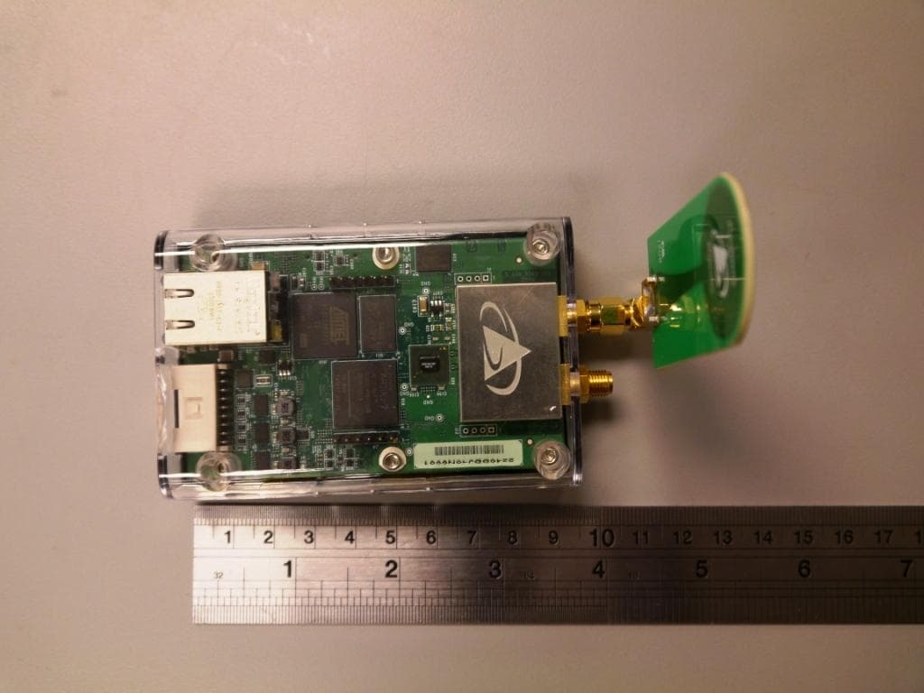
NUF-P440-A
Jan 26, 2016Ultra Wideband (UWB) radio transceiver
Equipment Class
UWB - Ultra Wideband Transmitter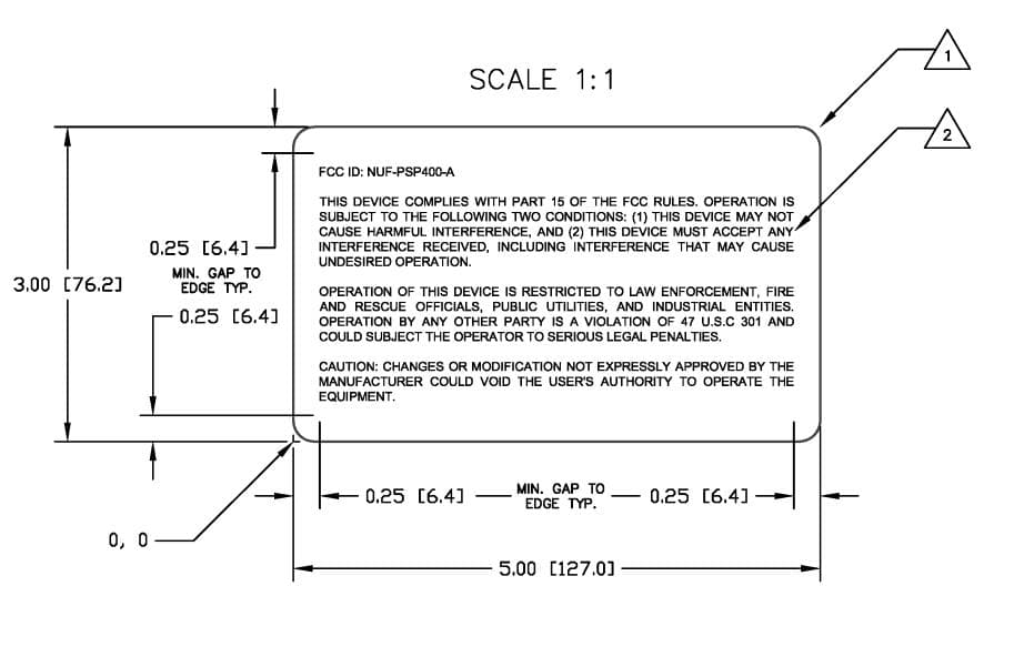
NUF-PSP400-A
Dec 21, 2014UWB Radar Surveillance System
Equipment Class
UWB - Ultra Wideband Transmitter
NUF-P412-A
Feb 03, 2013P412 Ultra Wideband radio transceiver
Equipment Class
UWB - Ultra Wideband Transmitter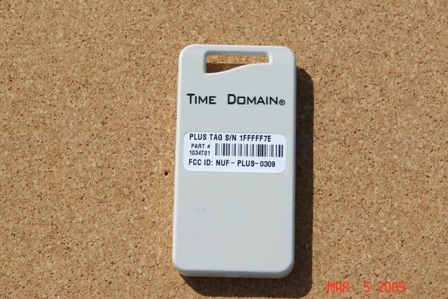
NUF-PLUS-0309
Apr 19, 2009PLUS Name Tag
Equipment Class
WBT - Wideband Transmitter