NUF-P350-1006THE PULSON P350 IS AN ACTIVE RFID SYSTEM (EAR99)
Humatics Corporation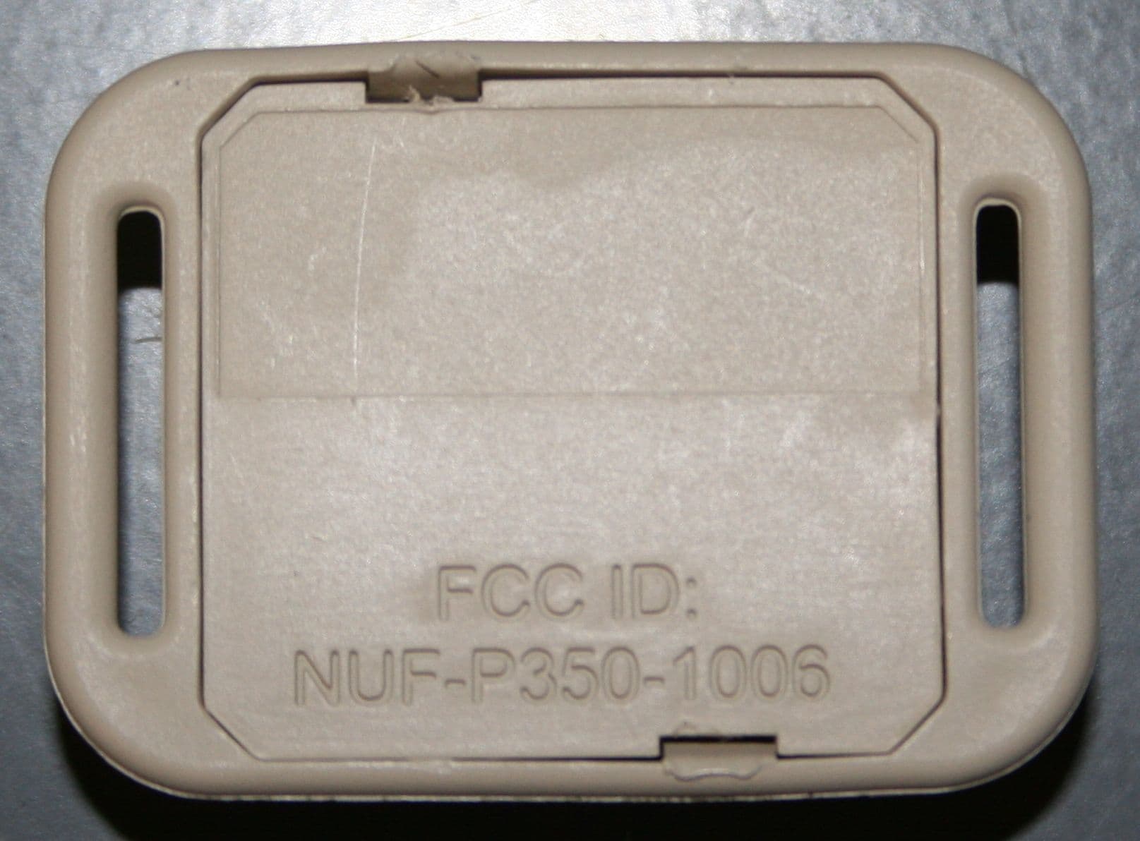
Click to zoom
Application Details
- Equipment Class
- WBT - Wideband Transmitter
- Date of Grant
- Apr 23, 2007
- Application Purpose
- Original Equipment
- Date of Application
- Mar 18, 2007
- Equipment Note
- THE PULSON P350 IS AN ACTIVE RFID SYSTEM (EAR99)
- Frequency Range
- 6221.00000000 - 6868.00000000
- Company
- Humatics Corporation
- Country
- United States
Documents & Files

Document Text
Text extracted from the exhibit documents filed with the FCC. Open a document above to read the original.
Users Manual
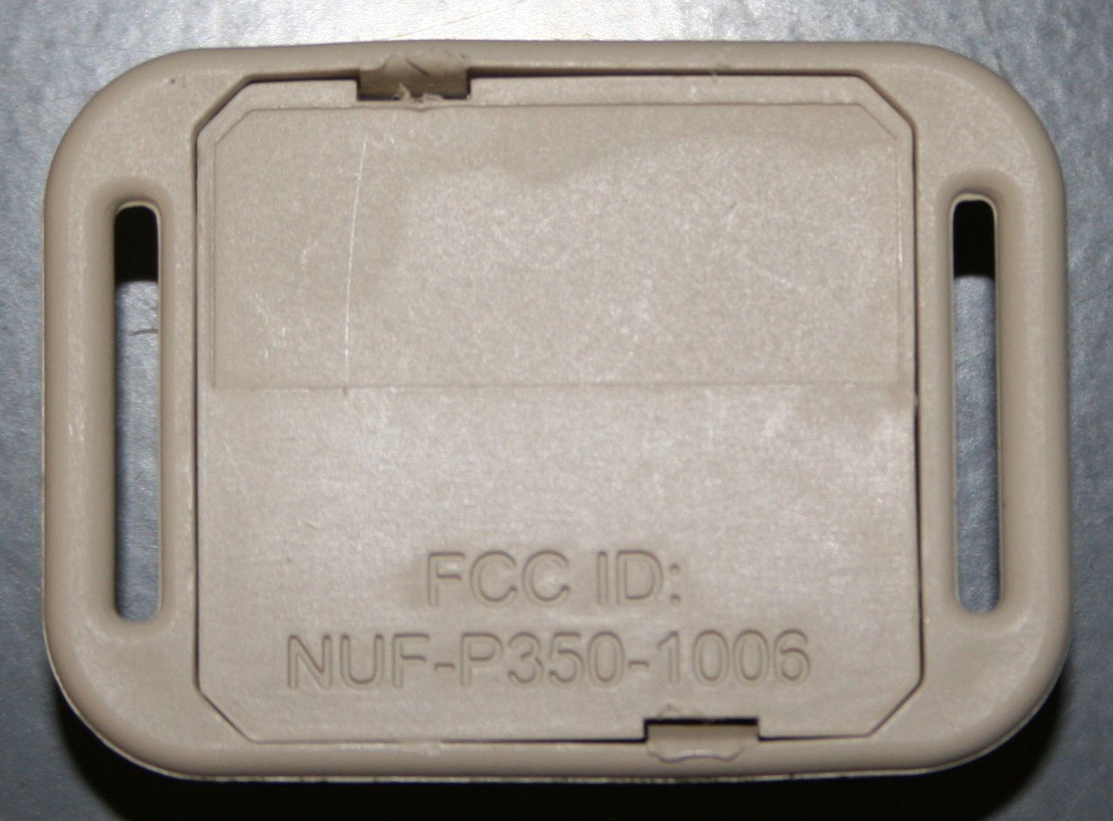
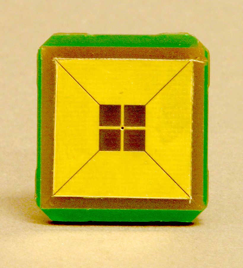
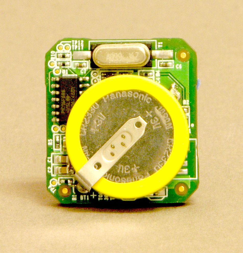
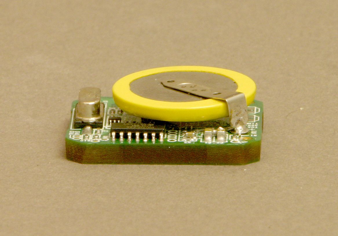
DRAFT P350-T010101 Tag User’s Manual PulsON 350 Active Radio Frequency Identification (RFID) Tracking System Time Domain Corporation Cummings Research Park 7057 Old Madison Pike Suite 250 Huntsville, AL 35806 USA http://www.timedomain.com Tel: +1.256.428.6481 +1.888.826.8378 ext 6481 Fax: +1.256.922.0387 P320-0170 March 2007 2 P350 Tag User’s Manual DRAFT Proprietary Information: Do not disclose unless authorized under a Nondisclosure Agreement and/or the Terms and Conditions signed at time of purchase Nondisclosure Provisions This manual contains Time Domain Corporation’s Confidential and Proprietary Information. Purchasers of this device are reminded of their obligation to protect TDC confidential and proprietary information in accordance with the Terms and Conditions (T&C) of sale. Copyright ©2001-2007 Time Domain Corporation. All rights reserved. Trademarks Time Domain® and PulsON® are registered trademarks of Time Domain Corporation. Ethernet® is a registered trademark of Xerox Corporation. The “PulsON Triangle” logo and PulsON 350™ are trademarks of Time Domain Corporation. Any trademarks, trade names, service marks or service names owned or registered by any other company and used in this manual are the property of its respective company. Rights Rights to use this documentation are set forth in the Terms and Conditions accompanying the PulsON 350 hardware. Regulatory Notice U.S. Operation . This device complies with Part 15 of the FCC Rules. Operation is subject to the following conditions: (1) this device may not cause harmful interference, and (2) this device must accept any interference received, including interference that may cause undesired operation. (3) Operation on board an aircraft or a satellite is prohibited. (4) Devices operating under this section may not be employed for the operation of toys. (5) Except for operation onboard a ship or a terrestrial transportation vehicle, the use of a fixed outdoor infrastructure is prohibited. A fixed infrastructure includes antennas mounted on outdoor structures, e.g., antennas mounted on the outside of a building or on a telephone pole. This outdoor infrastructure prohibition applies to intentional ultra-wideband (UWB) emitters. Operation in disregard of these conditions is a violation of 47 U.S.C. 301 and could subject the operator to serious legal penalties. Disassembling or modifying the unit will void FCC compliance and void Time Domain warranty provisions. Non-U.S. Operation : PulsON® technology has not been authorized for use or commercial exploitation under the regulations of any non-United States government agency. Please confer with your government’s regulatory agency to ensure proper authorizations are obtained. Please consult with Time Domain Corporation if you have any questions, prior to use. DRAFT P350 Tag User’s Manual 3 Proprietary Information: Do not disclose unless authorized under a Nondisclosure Agreement and/or the Terms and Conditions signed at time of purchase Table of Contents 1. INTRODUCTION ....................................................................................................................... 5 2. OVERVIEW ............................................................................................................................... 5 3. SPECIFICATIONS .................................................................................................................... 6 4. BEAM ORIENTATION RECOMMENDATIONS........................................................................ 6 WARRANTY ..................................................................................................................................... 7 4 P350 Tag User’s Manual DRAFT Proprietary Information: Do not disclose unless authorized under a Nondisclosure Agreement and/or the Terms and Conditions signed at time of purchase Active Change Record Version Comments Release Date Rev X Draft release 3/22/07 DRAFT P350 Tag User’s Manual 5 Proprietary Information: Do not disclose unless authorized under a Nondisclosure Agreement and/or the Terms and Conditions signed at time of purchase 1. Introduction The P350-T010101 Tag, hereafter referred to as the P350 Tag, is the transmitter for the P350 Ultra Wideband Active RFID Tracking System. It is small in size, durable, and with its long battery life, requires minimal maintenance. It has been certified by U.S. FCC to comply with Part 15 of the FCC Rules subject to the conditions listed under the Regulatory Notice on Page 2 of this manual. Figure 1-1 shows the tag’s FCC identification (ID) number with a sticker denoting its unique device ID. Figure 1-2 demonstrates the small size of the tag device. Figure 1-1 P350 Tag FCC ID Figure 1-2 P350 Tag 2. Overview Background Tag tracking is accomplished by analyzing time-differences-of-arrival (TDOAs) of tag transmissions. When a tag transmits a packet, readers that successfully receive the packet will send out information concerning the tag packet, including a precise timestamp. The difference in the timestamp between readers gives the TDOA for that reader pair/tag combination. At least three readers must hear a tag in order to determine a valid position for that tag. P350 Tag Within the P350 Ultra Wideband Active RFID Tracking System, the P350 Tag is used both to calibrate the tracking system readers and to track assets within the system. When used as a calibration tag, the tag’s unique id and position are input to the system. During the calibration process, the tag remains stationary at this location, transmitting ultra wideband (UWB) RF packets. As the readers “hear” and report time-of-arrival (TOA) data, a solution is determined and calibrated. The system must be calibrated before tag tracking can commence. When used to track assets, the tag is mounted on that asset, and through transmitted RF packets, sends its unique device ID and status. As the system readers hear the tag, the tag position is determined and the position is added …
Text truncated - open the document above for the full version.
Block Diagram
TX Tag ReceiverReceiver Receiver RF Signal CAT-5e Ethernet,10/100 Base-TTCP-IP Data Custom Hardwareand NetworkStandard Hardwareand NetworkInfrastructure PC Tracking Software CAT-5e Ethernet,10/100 Base-TTCP-IP Data CAT-5e Ethernet,10/100 Base-TTCP-IP Data Timing Signals Ethernet Hub SMA Connector forReceiver Antenna Power input48 VDC / 0.42A Receiver Function:y 2-Port Ethernet Switch y TOA Timestamp and PacketGeneration 90-240 VAC 1.4 A 50/60Hz Sync Distribution Panel:y Data Pass-Through y Timing Signal Injection y 24 Ports POE 48 VDC
Cover Letter(s)
Time Domain Corporation Cummings Research Park 7057 Old Madison Pike Huntsville, Alabama 35806 April 10, 2007 Mrs. Linda Elliott ([email protected]) FCC Application Processing Branch Re: FCC ID NUF-P350-1006 Applicant: Time Domain Corporation Correspondence Reference Number: 32772 731 Confirmation Number: EA897318 Dear Mrs. Elliot: In response to the FCC ID labeling issue on the TAG. We have a short-term and long-term solution. Short-term: We have produced approximately 3000 of the housing bottoms that have the FCC ID in the incorrect format. We intend to over label that area with the FCC ID in the correct format and the unit S/N. I have submitted the PDF of the new label (320-0173), the label stock is from Zebra, and the ribbon from Zebra. We use Zebra Ultimate 3000T label stock with the 5100 series resin based ribbon. The label size needed for the TAG will be custom. In the interim we will use a larger label stock and cut to size. Long-term: We will have the characters removed from the tool and have a nondescript bottom. In finally assembly we will continue to use the label as recommended in the short-term. The current tool is a "soft-tool" with a limited production life. When we order a new tool we will include the FCC ID in the correct format as shown in our newly submitted drawing. Cal Tag: When a tag is installed in the antenna housings the FCC ID label (320-0173) will be placed as shown in the antenna assembly drawing (10A-0058E). Yours truly, Keven Trach Compliance Engineer Time Domain Corp. Phone: 256 428 317FAX: 256 922 0387 [email protected]
ID Label/Location Info
310-0325A.par 310-0325A 1 1 desiree.delane 9/27/2006 desiree.delane 9/27/2006 Mech, TOA TAG Bottom Housing, no logo A BC D 1 2 3 4 A B C D 1 2 3 4 NOTES: 1. MATERIAL: HDPE, FLAME RATING TO BE UL94 V-0 ; COLOR TO BE PEARL WHITE 2. GEOMETRY TO BE BASED ON 3D CAD DATA FINISH: TEXTURE INDICATED SURFACES TO MOLD-TECH MT11000 .0004” DEEP FINISH: POLISH INDICATED SURFACES SPI A-2 1.176 1.276 .305 1° 10° R .010 (4X) AA VIEW A-A .055 X 45° (4X) .059(TYP) 1.058 R .464 (2X) .497 .059 .033(2X) 1.158 .497 .256 .786 (2X) .204 (2X) 1.267 .004 BB SECTION B-B C C SECTION C-C 1.067 ±.005 1.158 ±.005 1°(TYP) 3 4 (ALL AROUND) 4 3
ID Label/Location Info
310-0325A.par 310-0325A 1 1 desiree.delane 9/27/2006 desiree.delane 9/27/2006 Mech, TOA TAG Bottom Housing, no logo A BC D 1 2 3 4 A B C D 1 2 3 4 NOTES: 1. MATERIAL: HDPE, FLAME RATING TO BE UL94 V-0 ; COLOR TO BE PEARL WHITE 2. GEOMETRY TO BE BASED ON 3D CAD DATA FINISH: TEXTURE INDICATED SURFACES TO MOLD-TECH MT11000 .0004” DEEP FINISH: POLISH INDICATED SURFACES SPI A-2 1.176 1.276 .305 1° 10° R .010 (4X) AA VIEW A-A .055 X 45° (4X) .059(TYP) 1.058 R .464 (2X) .497 .059 .033(2X) 1.158 .497 .256 .786 (2X) .204 (2X) 1.267 .004 BB SECTION B-B C C SECTION C-C 1.067 ±.005 1.158 ±.005 1°(TYP) 3 4 (ALL AROUND) 4 3
Operational Description
ITEM: PulsON 350 UWB Active RFID System Technical Description The PulsON P350 is an active RFID system based on ultra wideband technology. It’s primary use is for the location and identification of people or objects which are equipped with a small RF tag. Technical Rationale The PulsON 350 (P350) is based on similar ultra wideband (UWB) technology, and has similar functionality, to the PulsON 210 RD which has already been granted an ECCN of EAR99 granted on CCATS G040004. The P350 has reduced functionality when compared to the P210 RD, being designed to operate exclusively as an active RFID system with a real time location (RTLS) capability. In order to reduce costs sufficiently for volume deployment, the P350 also uses a simpler form of UWB than the P210, resulting in slightly reduced performance. The P350 system is comprised of the following components: Tag: The tag is a small, transmit-only device which emits data packets at a constant (pre-programmed) rate. The data packets include a tag identification code, status information, and time of arrival measurement waveforms. Reader: The reader is a receiver which is permanently mounted in the area of coverage. The reader reads and decodes the data packet from the tag, and also ascertains the time of arrival of the packet at the receiver. Synchronization Distribution Panel: The synchronization distribution panel (SDP) distributes a timing signal to multiple receivers in order that the times of arrival measured by each have a common time base. The SDP additionally powers the receivers over Ethernet cable, and passes the decoded data and measured times of arrival to other Ethernet devices. The P350 system is delivered with documentation describing the use and installation of the system. It is also delivered with a software interface specification allowing a developer to interface software that computes the location of the tags (from the measured times of arrival ). Additionally, a simple position solver is included as a dynamic link library (DLL) along with a software executable that plots the location of the tags in real time on a computer display, and displays certain diagnostic information useful for installation and testing. Technical Documentation/Specifications Origin Declaration The P350 system has been developed entirely with private capital, and contains no military parts. It has not yet been sold. Its purpose is the location and identification of tags which are attached either to people or to objects. 1. Proved a block diagram, short description, technical specifications, and potential use of this item. Potential uses include: • Tracking patients, caregivers and equipment in a healthcare facility • Locating inventory in a warehouse • Tracking goods in a manufacturing process • Tracking retail items in a retail facility • Tracking personnel in dangerous environments, e.g. a petrochemical facility In general the uses of this product include tracking people or objects for the purpose of improving business process efficiency, for improving the security of a facility, or for improving the safety of personnel. 2. Has this item been exported before, if yes, please provide a Z or D number? No 3. Provide sales history in percentage, commercial vs. military. No sales yet. 4. Is there any encryption on the system? No.
Parts List/Tune Up Info
BILL OF MATERIAL Assembly # E Description Originator Engineer Date Item No. Part No. Rev. Qty. U/M Description Ref. Des. / Notes 1 240-0040 B 1 EACH 2 240-0041 B 1 EACH 3 240-0042 C 1 EACH 4 240-0044 B 1 EACH 5 200-0191 F1 1 EACH 6 220-0192 B 1 EACH 7 N/A 8 040-0151 1 EACH 9 040-0152 1 EACH 10 320-0173 A 1 EACH 11121314151617181920 REFERENCE DOCUMENTS: (NOTE: Documents will be linked to the assembly part number.) Document Number Revision Notes 10A-0058 E APPROVALSOriginator Date Mgmt. Approval. Date Engineer Date Document Control Date DescriptionAss'y Drawing, P350 Receiver Antenna, Omni Directional Rev. Unit Assembly, P350 Receiver Antenna, Omni Directional JOE ANDERSON JOE ANDERSON 04-Apr-07 100-0058 Cable Tie Holder, 4wayLabel, Printed, P350 TAG SN W/ FCC IDCable Tie, Nylon Natural Color, 4" Nom. LengthSub-Assembly, Ceiling Mount BracketSub-Assembly, Antenna BracketSub-Assembly, P350 Omni Antenna Ground PlaneSub-Assembly, P350 Omni Antenna CoverCable Assy, Cal TAG InterfacePWA, TOA Calibration TAG 778470.XLS Page 1 of 1 405-0019A BOM FORM
Schematics
5 5 4 4 3 3 2 2 1 1 DD CC BB AA Project SizeDocument Rev Date: Sheet of ORIGINATOR ENGINEER APPROVED RELEASED THIS DESIGN AND PRINT IS THE PROPERTY OF TIME DOMAIN CORPORATION THIS DOCUMENT CONTAINS PROPRIETARY INFORMATION AND IS LOANED IN CONFIDENCE. THIS DOCUMENT IS SUBJECT TO RETURN UPON DEMAND ON THE EXPRESS CONDITION THAT IT WILL NOT BE USED IN ANY WAY NOT AUTHORIZED BY TIME DOMAIN CORPORATION. APPROVALSDATE Sheet Title 20S-0195 E2 TOA TAG1 B 12 7057 Old Madison Pike Huntsville, AL 35806 Wednesday, January 10, 2007 <Variant Name>12 7057 Old Madison Pike Huntsville, AL 35806 Wednesday, January 10, 2007 <Variant Name>12 7057 Old Madison Pike Huntsville, AL 35806 Wednesday, January 10, 2007 <Variant Name> Project SizeDocument Rev Date: Sheet of Project SizeDocument Rev Date: Sheet of ORIGINATOR ENGINEER APPROVED RELEASED THIS DESIGN AND PRINT IS THE PROPERTY OF TIME DOMAIN CORPORATION THIS DOCUMENT CONTAINS PROPRIETARY INFORMATION AND IS LOANED IN CONFIDENCE. THIS DOCUMENT IS SUBJECT TO RETURN UPON DEMAND ON THE EXPRESS CONDITION THAT IT WILL NOT BE USED IN ANY WAY NOT AUTHORIZED BY TIME DOMAIN CORPORATION. APPROVALSDATE Sheet Title 20S-0195 E2 TOA TAG1 B ORIGINATOR ENGINEER APPROVED RELEASED THIS DESIGN AND PRINT IS THE PROPERTY OF TIME DOMAIN CORPORATION THIS DOCUMENT CONTAINS PROPRIETARY INFORMATION AND IS LOANED IN CONFIDENCE. THIS DOCUMENT IS SUBJECT TO RETURN UPON DEMAND ON THE EXPRESS CONDITION THAT IT WILL NOT BE USED IN ANY WAY NOT AUTHORIZED BY TIME DOMAIN CORPORATION. APPROVALSDATE Sheet Title 20S-0195 E2 TOA TAG1 B PIC16F688 MICRO- CONTROLLER PROGRAMMING PINS SLEEP TIMER 3 VOLT BATTERY USART SDATA SCLK LOGIC TO COMBINE DATA & CLK TRANSMITTER Transmitter Control TRANSMIT ENABLE PULSE GENERATION Encoded Data/Clk ANTENNA POWER CONTROL CALIBRATION CONNECTOR PWR & TAG LEDS FUNCTIONS IN DASHED LINES ARE ONLY INSTALLED FOR CALIBRATION VERSION OF TAG DAVID BAILEY DAVID BAILEY BLOCK DIAGRAM 5 5 4 4 3 3 2 2 1 1 DD CC BB AA DATA CLK nPWRON EXT_TIME1 EXT_TIME2 EXT_TIME1 EXT_TIME2 VRAW SW_PWR SW_PWR VBATT VRAW VBATT SW_PWR Project SizeDocument Rev Date: Sheet of ORIGINATOR ENGINEER APPROVED RELEASED THIS DESIGN AND PRINT IS THE PROPERTY OF TIME DOMAIN CORPORATION THIS DOCUMENT CONTAINS PROPRIETARY INFORMATION AND IS LOANED IN CONFIDENCE. THIS DOCUMENT IS SUBJECT TO RETURN UPON DEMAND ON THE EXPRESS CONDITION THAT IT WILL NOT BE USED IN ANY WAY NOT AUTHORIZED BY TIME DOMAIN CORPORATION. APPROVALSDATE Sheet Title 20S-0195 E2 TOA TAG1 B 22 7057 Old Madison Pike Huntsville, AL 35806 Wednesday, January 10, 2007 <Variant Name> Project SizeDocument Rev Date: Sheet of ORIGINATOR ENGINEER APPROVED RELEASED THIS DESIGN AND PRINT IS THE PROPERTY OF TIME DOMAIN CORPORATION THIS DOCUMENT CONTAINS PROPRIETARY INFORMATION AND IS LOANED IN CONFIDENCE. THIS DOCUMENT IS SUBJECT TO RETURN UPON DEMAND ON THE EXPRESS CONDITION THAT IT WILL NOT BE USED IN ANY WAY NOT AUTHORIZED BY TIME DOMAIN CORPORATION. APPROVALSDATE Sheet Title 20S-0195 E2 TOA TAG1 B 22 7057 Old Madison Pike Huntsville, AL 35806 Wednesday, January 10, 2007 <Variant Name> Project SizeDocument Rev Date: Sheet of ORIGINATOR ENGINEER APPROVED RELEASED THIS DESIGN AND PRINT IS THE PROPERTY OF TIME DOMAIN CORPORATION THIS DOCUMENT CONTAINS PROPRIETARY INFORMATION AND IS LOANED IN CONFIDENCE. THIS DOCUMENT IS SUBJECT TO RETURN UPON DEMAND ON THE EXPRESS CONDITION THAT IT WILL NOT BE USED IN ANY WAY NOT AUTHORIZED BY TIME DOMAIN CORPORATION. APPROVALSDATE Sheet Title 20S-0195 E2 TOA TAG1 B 22 7057 Old Madison Pike Huntsville, AL 35806 Wednesday, January 10, 2007 <Variant Name> CALIBRATION TAG CONNECTIONS MICROCONTROLLER CIRCUITRY DAVID BAILEY DAVID BAILEY W=30 L=175 W=5 L=130 ANTENNA W=30 L=175 VIA DNLDNL R12 90.9 R12 90.9 BT1 CR2330_SMT BT1 CR2330_SMT TP10TP10 R5 150 R5 150 TP21TP21 D2 LTST-S270KSKT YLW D2 LTST-S270KSKT YLW TP17TP17 C4 2200pF C4 2200pF TP3TP3 TP6TP6 R11 1K R11 1K C9 0.01uF C9 0.01uF TP5TP5 R3 1M R3 1M TP12TP12 Y1 3.9975MHz Y1 3.9975MHz TP20TP20 R4 2.21K R4 2.21K TP1TP1 C5 0.22uF C5 0.22uF R6 3M 5% R6 3M 5% 3 4 1 5 2 6 G SD Q1 Si1499DH G SD Q1 Si1499DH D1 LTST-S270KGKT GREEN D1 LTST-S270KGKT GREEN C3 0.1UF C3 0.1UF TP19TP19 TP23TP23 R2 100K R2 100K R7 1M R7 1M TP8TP8 C1 22uF C1 22uF R8 3M 5% R8 3M 5% TP4TP4 TP2TP2 C8 10PF C8 10PF TP24TP24 TP9TP9 TP16TP16 C7 22pF C7 22pF TP15TP15 R1 604 R1 604 1 2 4 5 3 U2 NC7SZ02P5X U2 NC7SZ02P5X TP18TP18 C12 3.9pF C12 3.9pF TP13TP13 R13 604 R13 604 TP22TP22 C11 100pF C11 100pF C2 22uF C2 22uF 1 2 3 4 Q2 BFP405FE6327 Q2 BFP405FE6327 TP14TP14 VDD 1 RA5/T1CKI/OSC1/CLKIN 2 RA4/AN3/T1G/OSC2/CLKOUT 3 RC5/RX/DT 5 RC4/C2OUT/TX/CK 6 RC3/AN7 7 RC2/AN6 8 RC1/AN5/C2IN- 9 RC0/AN4/C2IN+ 10 RA2/AN2/T0CKI/INT/C1OUT 11 RA1/AN1/C1IN-/VREF/ICSPCLK 12 RA0/AN0/C1IN+/ICSPDAT/ULPWU 13 VSS 14 RA3/MCLR/VPP 4 U1 PIC16F688 U1 PIC16F688 C10 0.01uF C10 0.01uF C6 22pF C6 22pF 1 2 3 4 J1 87438-0443 J1 87438-0443 TP7TP7 R9 3M 5% R9 3M 5% R10 0 R10 0 TP11TP11
Test Report
Client: Product Designation: Next Tag Report Number: 3108830ATL-002 All services undertaken are subject to the following general policy: This report is for the exclusive use of Intertek's Client and is provided pursuant to the agreement between Intertek and its Client. Intertek's responsibility and liability are limited to the terms and conditions of the agreement. Intertek assumes no liability to any party, other than to the Client in accordance with the agreement, for any loss, expense or damage occasioned by the use of this report. Only the Client is authorized to copy or distribute this report and then only in its entirety. Any use of the Intertek name or one of its marks for the sale or advertisement of the tested material, product or service must first be approved in writing by Intertek. The observations and test results in this report are relevant only to the sample tested. This report by itself does not imply that the material, product, or service is or has ever been under an Intertek certification program. This report must not be used to claim product endorsement by A2LA, NIST, or any agency of the US Government. Tested by: Tests performed by:Report reviewed by: Standard: Shawn K. McGuinness Senior Associate Engineer David J. Schramm EMC Department Manager Time Domain Cor poration 6700 Odessey Drive Contact: Keven Trach Phone: (256) 428-6317 Fax: (256) 922-0387 TEST REPORT February 28, 2007 Intertek Testing Services NA Inc. 1950 Evergreen Blvd., Suite 100 Duluth, GA 30096 FCC Part 15.250 - Operation of wideband systems within the band 5925 to 7250 MHz Page 1 of 21EMC Report for Time Domain Corporation on the Next Tag 02/28/2007Report Number: 3108830ATL-002Issued: Intertek 2.0 Test Summary 1.0 Introduction and Conclusion Test DateTest Full NameResultSection System setup including cable interconnection details, support equipment and simplified block diagram. (System Setup)4.0 02/27/200715.250(a) and 15.250(b): -10 dB Bandwidth requireqments (Bandwidth)PASS5.0 02/27/200715.250(d)(1) Radiated power (EIRP) density (EIRP power density)PASS6.0 02/27/2007Peak Power in a 50 MHz bandwidth (Peak Power per 50 MHz)PASS7.0 02/27/2007Radiated emissions below 960 MHz (Radiated Emissions (<960 MHz))PASS8.0 02/27/200715.250(d)(2) Radiated power (EIRP) density in GPS receive bands (EIRP power density (GPS))PASS9.0 The tests indicated in section 2.0 were performed on the product constructed as described in section 3.0. The remaining test sections are the verbatum text from the actual data sheets used during the investigation. These test sections include the test name, the specified test Method, a list of the actual Test Equipment Used, documentation Photos, Results and raw Data. No additions, deviations, or exclusions have been made from the standard(s) unless specifically noted. Based on the results of our investigation, we have concluded the product tested complies with the requirements of the standard(s) indicated. The results obtained in this test report pertain only to the item(s) tested. Page 2 of 21EMC Report for Time Domain Corporation on the Next Tag 02/28/2007Report Number: 3108830ATL-002Issued: Intertek 3.0 Description of Equipment Under Test Equipment Under Test Description Manufacturer Model Number Serial Number UWB Transmitter Time Domain Next Tag Not labeled EUT receive date: February 26, 2007 EUT receive condition: Good Description of EUT provided by Client: The Tag is a simple UWB transmit-only device for a RFID (Radio Frequency Identification) Tracking System, which sends out very short packets at predetermined transmission rates. These very short packets (less than 100 microseconds) allows for several thousand tags to be tracked in the same area. The data in the tag packet includes the tags ID, a packet number, battery status, and a received signal strength indicator. Description of EUT exercising: The Tag transmits its normal signal at all times. There is no user control to change its power level or mode of operation. Page 3 of 21EMC Report for Time Domain Corporation on the Next Tag 02/28/2007Report Number: 3108830ATL-002Issued: Intertek System setup including cable interconnection details, support equipment and simplified block diagram. (System Setup) 4.0 Method: Record the details of EUTcabling, document the support equipment, and show the interconnections in a block diagram. EUT EUT is battery powered and has no interconnecting cables Setup block diagram Drawing: Page 4 of 21EMC Report for Time Domain Corporation on the Next Tag 02/28/2007Report Number: 3108830ATL-002Issued: Intertek System setup including cable interconnection details, support equipment and simplified block diagram. (System Setup) 4.0 None Support Equipment DescriptionManufacturerModel NumberSerial Number None Description EUT Cabling Connection Length Shielding FerritesIDFromTo Data: Page 5 of 21EMC Report for Time Domain Corporation on the Next Tag 02/28/2007Report Number: 3108830ATL-002Issued: Intertek 15.250(a) and 15.250(b): -10 dB Bandwidth requireqments (Bandwidth)5.0 Method: The -10 dB bandwidth of a device operating under the provisions of this section must be contained within the 5925–7250 MHz band under all conditions of operation including the effects from stepped frequency, frequency hopping or other modulation techniques that may be employed as well as the frequency stability of the transmitter over expected variations in temperature and supply voltage. The -10 dB bandwidth of the fundamental emission shall be at least 50 MHz. For transmitters that employ frequency hopping, stepped frequency or similar modulation types, measurement of the -10 dB minimum bandwidth specified in this paragraph shall be made with the frequency hop or step function disabled and with the transmitter operating continuously at a fundamental frequency following the provisions of §15.31(m). The -10 dB bandwidth is based on measurement using a peak detector, a 1 MHz resolution bandwidth, and a video bandwidth greater than…
Text truncated - open the document above for the full version.
Contact Information
Applicant
Alan Petroff
Technical Contact
Time Domain CorporationKeven Trach
[email protected]256-428-6317
7057 Old Madison Pike · Huntsville, Alabama · United States
Test Firm
Intertek Testing Services NA Inc.Charles Parker
Technical Specifications
| # | Rule Parts | Frequency Range | Power Output |
|---|---|---|---|
| 1 | 15.250 | 6.22 GHz - 6.87 GHz | - |
Other Applications from Humatics Corporation
NUF-C445-A
Feb 25, 2020Ultra wideband radio
Equipment Class
UWB - Ultra Wideband Transmitter
NUF-P440-A
Jan 26, 2016Ultra Wideband (UWB) radio transceiver
Equipment Class
UWB - Ultra Wideband Transmitter
NUF-PSP400-A
Dec 21, 2014UWB Radar Surveillance System
Equipment Class
UWB - Ultra Wideband Transmitter
NUF-P412-A
Feb 03, 2013P412 Ultra Wideband radio transceiver
Equipment Class
UWB - Ultra Wideband Transmitter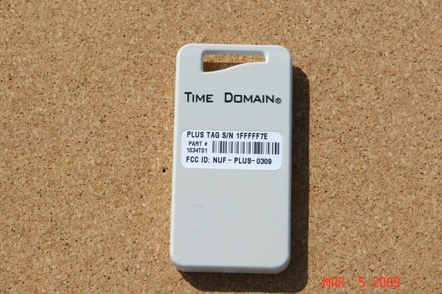
NUF-PLUS-0309
Apr 19, 2009PLUS Name Tag
Equipment Class
WBT - Wideband Transmitter