NUF-CWRadar Vision System
Humatics Corporation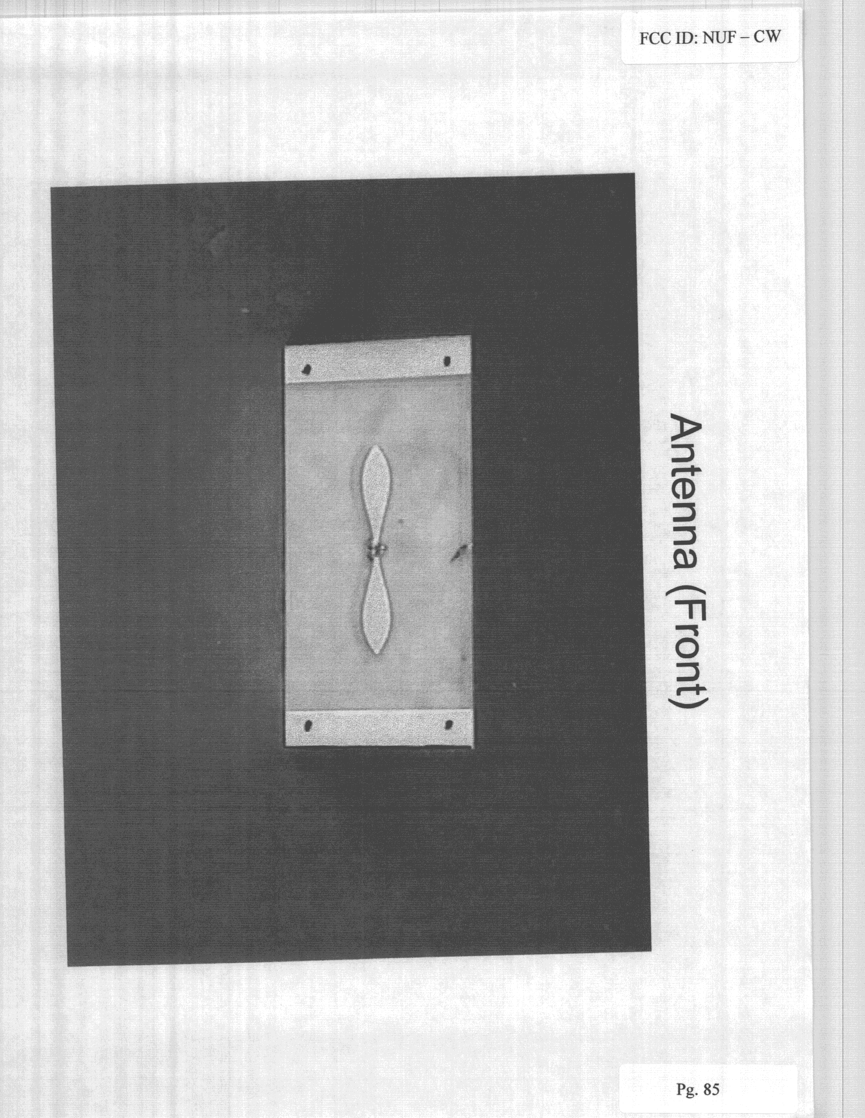
Click to zoom
Application Details
- Equipment Class
- UWB - Ultra Wideband Transmitter
- Date of Grant
- Sep 11, 2000
- Application Purpose
- Original Equipment
- Date of Application
- Jul 16, 1998
- Equipment Note
- Radar Vision System
- Frequency Range
- 1000.00000000 - 3000.00000000
- Company
- Humatics Corporation
- Country
- United States
Documents & Files
Document Text
Text extracted from the exhibit documents filed with the FCC. Open a document above to read the original.
Operational Description
Theory of Operation of RadarVision This document describes, at a high level, the theory of operation of Time Domain’s RadarVision with specific attention on how the transmitted signal is generated. RadarVision is a coherent, range gated, proximity detection Time Modulated Ultra- Wideband (TM-UWB) radar. It is intended for use by law enforcement and other public safety officials. With this device, a public safety officer could determine whether or not there is motion on the other side of a nonmetallic boundary. RadarVision can also indicate the approximate range of that movement. For example, the device could be used by a police officer to assess the situation prior to forcibly entering a building. Detection of motion would warn the user of probable complications with the entry, whereas the absence of motion would yield relative confidence concerning the safety of the entry. The device could also be used to determine if an intruder was hiding in a darkened alley or in foliage. The following functional block diagram illustrates the key RadarVision components. Following this diagram is a description of each component of the system as well as an overview of the operating software. Figure 1: RadarVision I Functional Block Diagram 20 MHz Clock RF PULSE GENERATOR Analog Radio Frequency PSUEDO- NOISE GENERATOR TEMPLATE GENERATOR CORRELATOR x S/H BUFFER DELAY EXTERNAL USER I/O (KEYPAD, LCD DISPLAY, & AUDIO ALARM) MICRO- PROCESSOR AMP A/D TIME DELAY WORD TRIGGER SIGNAL + PPM POS Divide by 4 NOISE CODER BUFFER PPM POS Clock and Noise Coder The clock and noise coder circuits generate the base timing signal for the radar. The output from a 20 MHz oscillator is divided by four to create 200 nanosecond Timing Windows. The Noise Coder produces a Trigger Signal at a pseudo-random time, as determined by a code word from the Pseudo-Random Noise Generator, in the first 20 nanoseconds of each Timing Window using a pulse position modulator (PPM). The Trigger Signal is sent to the RF Pulse Generator. In a similar fashion, another PPM is used to position a trigger for the correlator as determined by the summation of the code word and delay word. These triggers are illustrated in Figure 2. Figure 2: RadarVision timing diagram RF Pulse Generation and Antenna The Trigger Signal is used to control the timing of a radio frequency (RF) pulse. The RF Pulse Generator has a high pass filter to provide extra electromagnetic compatibility with systems below 1 GHz. This short RF pulse is radiated from the antenna at a precise moment in time. In order to maintain the coherence of the radar, it is critical that the timing of the radiated pulse be accurately controlled. In practice, the timing of these RF pulses has a precision of 5 ps and an RMS accuracy of 20 ps. The RF pulse generated is approximated by the second derivative of a Gaussian pulse. The pulse is produced using a Step Recovery Diode (SRD) and a 1 GHz high pass filter circuit. Basically, an SRD is initially charged and then reverse biased by the Trigger Signal. Reverse biasing the SRD produces a very fast, rising edge. This edge is then high passed to produce the RF pulse. The RF pulse is then radiated from the antenna. The emitted signal has the following characteristics: 200 ns window Time Delay Word 20 ns Timing Window Trigger Signal (to RF Pulse Gen) Delayed Signal (to Template Gen) Pulse Width: 500 ps Center Frequency:2 GHz 3 dB Bandwidth: nominally1.5 GHz 6 dB Bandwidth:2 GHz Average Transmit Power:approximately 42 uW EIRP. Average Field Strength:<500 uV/m at 3 m when measured with a resolution bandwidth of 1 MHz. Antenna Gain:7 dBi Range Delay The 20 MHz clock is divided to generate a 5 MHz clock. This is sent to a PPM that is controlled by the summation of the code word from the Pseudo-Random Noise Generator and a delay word from the Microprocessor. The final result is a Delayed Trigger Signal that is synchronized to the Trigger Signal but delayed by the amount of time specified by the Time Delay Word. The resulting delayed signal is then sent to the correlator. Correlator and Delay The Correlator is the heart of the receiver and can be thought of as an integrating mixer or four quadrant multiplier. Reflected energy is received by the antenna, amplified and sent to the IF port of the mixer. The mixer LO input is connected to the output of the Template Generator. The delayed Trigger Signal is used to fire the Template Generator. Firing the Template Generator produces a Gaussian pulse waveform. The mixer multiplies this pulse by the RF energy received by the antenna. The result of the multiplication is integrated over the period of the pulse and is then captured by the Sample and Hold (S/H) circuit. The S/H is triggered by a Delay circuit. The Delay circuit trigger signal is produced by slightly delaying the output of the Range Delay triggering circuit. This additional delay compensates for the delay inherent in the correlation and integration process. Micro-Processor and User Interface The microprocessor provides several functions. First, it uses an Analog to Digital converter to measure the output of the Sample and Hold. The microprocessor can then integrate this signal over time. Second, the microprocessor can set and change the value of the Time Delay Word send to the Range Delay circuit. Third, detection algorithms (described in the following section) are used to process the received energy and generate various alarms. Fourth, the microprocessor monitors the keyboard for user input, displays the results on the LCD display and generates audio alarms. Processing Algorithms The basic algorithmic approach is to measure a quasi-impulse response of the environment and to monitor that response for changes. If changes are significant, then a hit is determined. Once a specified number of consecutive hits are detected, an alarm is reported. The response of the environment is measured at four fixed ranges. The microprocessor controls the ranges by controlling th…
Text truncated - open the document above for the full version.
Contact Information
Applicant
Alan Petroff
Technical Contact
Time Domain CorporationRachel Reinhardt
[email protected]256-922-9229
6700 Odyssey Drive · Huntsville, Alabama · United States
Non-Technical Contact
Wiley, Rein FieldingDavid Hilliard
[email protected]202-429-7058
Test Firm
DLS Electronic Systems, Inc.Donald Sweeney
847-537-6400
Technical Specifications
| # | Rule Parts | Frequency Range | Power Output | Tolerance |
|---|---|---|---|---|
| 1 | 15C | 1.00 GHz - 3.00 GHz | - | % |
Other Applications from Humatics Corporation
NUF-C445-A
Feb 25, 2020Ultra wideband radio
Equipment Class
UWB - Ultra Wideband Transmitter
NUF-P440-A
Jan 26, 2016Ultra Wideband (UWB) radio transceiver
Equipment Class
UWB - Ultra Wideband Transmitter
NUF-PSP400-A
Dec 21, 2014UWB Radar Surveillance System
Equipment Class
UWB - Ultra Wideband Transmitter
NUF-P412-A
Feb 03, 2013P412 Ultra Wideband radio transceiver
Equipment Class
UWB - Ultra Wideband Transmitter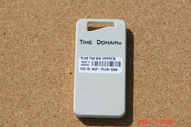
NUF-PLUS-0309
Apr 19, 2009PLUS Name Tag
Equipment Class
WBT - Wideband Transmitter