NUOUT-20NP02USB 2.0 Card Bus
Unixtar Technology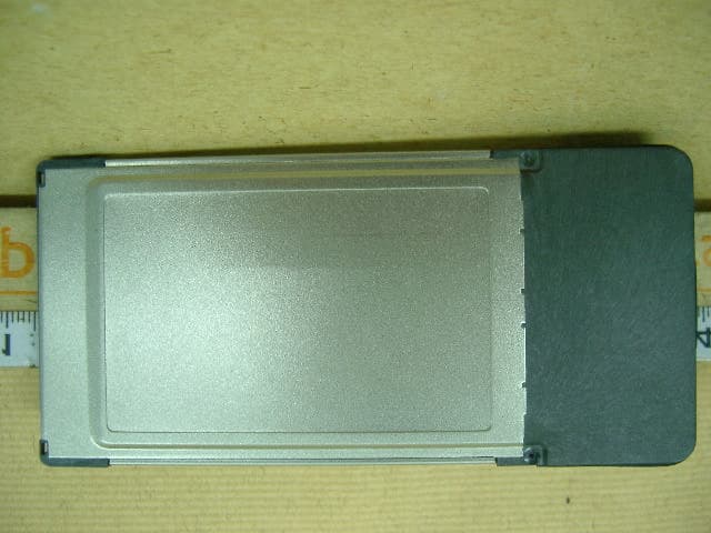
Click to zoom
Application Details
- Equipment Class
- JBP - Part 15 Class B Computing Device Peripheral
- Date of Grant
- Jul 21, 2002
- Application Purpose
- Original Equipment
- Date of Application
- Jul 21, 2002
- Equipment Note
- USB 2.0 Card Bus
- Company
- Unixtar Technology
- Country
- Taiwan
Documents & Files
Document Text
Text extracted from the exhibit documents filed with the FCC. Open a document above to read the original.
Users Manual
1 2 3 USB 2.0 Hi-speed 2 Port CardBus User’s Manual 1. USB 2.0 Hi-Speed 2 port CardBus 2. Driver for Windows/Mac in CD-ROM 3. USB Charger Cable x1 4. USB 2.0 cable x1 5. User’s Manual Warning: Normally internal power will not supply sufficient power for devices which require larger power consumption (USB 2.0 peripherals for instant), to avoid any possible operational failure of devices, it is recommended USB Charger cable is to be linked, in case, the devices still not function properly, please replace it with external AC Adapter. External AC Adapter is to be purchased separately This USB2.0 Hi-Speed 2 port CardBus is compliant with latest USB Spec Revision 2.0, i.e. support high-speed (480 Mbps), full-speed (12 Mbps) and low-speed (1.5 Mbps) data transaction rate. It is fully backward compatible with previous USB 1.1 products. You will enjoy the Hi-Speed that USB2.0 technology provides, particularly when you are operating the devices, which need mass data transaction, such as DV Camcorder, Digital camera...etc λ Compliant with USB Spec Revision 2.0 λ Compliant with Open Host Controller Interface Spec for USB Revision 1.0a λ All 2 downstream ports can handle high-speed (480 Mbps), full-speed (12 Mbps) and low-speed (1.5 Mbps) transaction rate λ All 2 downstream ports are shared by OHCI and EHCI Host Controller core λ Plug and Play capability λ USB Charger Cable λ Use with IBM PC compatible λ Use with Mac PowerBook compatible λ Recommended CPU speed at Pentium III or AMD-K7 or higher, RAM 128MB λ Recommended CPU is G3 300, RAM 128MB λ Windows 98, 98SE, ME, Windows 2000 and Windows XP* λ Mac OS X 10.1(Support USB 2.0 Driver) λ Mac OS 9.1(Only support USB 1.1) λ Available Type II CardBus-enabled slot. λ Available USB port for computer. 4 5 6 1. Turn on your computer and insert the Driver CD. And desktop will show the USB 2.0 Hi-speed PCI Card Window (or click CD-ROM:\ setup.exe). Please click [Install USB 2.0 driver] to install USB 2.0 driver. 2. After setup is completed, select [Yes, I want to restart my computer now.], and click [Close] button, computer will restart automatically. 3. After computer is restarted completely, connect USB Charger Cable to the USB port of your computer or plug external AC Adapter into the power socket. 4. Connect USB Charger Cable or external AC Adapter power cord to the USB2.0 Hi-Speed 2 port CardBus jack. 5. Push firmly unit USB2.0 Hi-Speed 2 port CardBus clicks into available Type II CardBus-enabled slot of your computer. 6. Turn on your computer, the Windows will detect a new USB device and run Add New Hardware Wizard, NEC PCI to USB Enhanced Host Controller, USB 2.0 Root Hub Device, and NEC PCI to USB Open Host Controller. 1. Turn on your computer and insert the Driver CD. And open the Driver CD, Double-click the icon 2. After setup is completed, click [Restart] button. 3. After computer is restarted completed, connect USB Charger Cable to the USB port of your computer or plug external AC Adapter into the power socket. 4. Connect USB Charger Cable or external AC Adapter power cord to the USB2.0 Hi-Speed 2 port CardBus jack. 5. Push firmly unit USB2.0 Hi-Speed 2 port CardBus clicks into available Type II CardBus-enabled slot. 6. Verify that the card is seen by your computer by clicking Apple System Profiler. Then, click the Devices and Volumes tab. NOTE: 1. If you want to update the driver, please visit http://www.orangeware.com/usb2oem.html and read the ReadMe.doc file before installation. 2. Mac OS 9.x only support USB 1.1, no support USB 2.0 Interface 2 USB Type- A ports Standards Compliance Meets USB 2.0 specs EHCI and OHCI compatible Transaction Speed Support high speed (480 Mbps) and full speed (12 Mbps) and low speed(1.5 Mbps) Operating temperature 0 to 70 Operating humidity 5% to 90% (non-condensing) Dimension 114.0 mm (L) x 53.8 mm (W) x 14.25 mm (H) Weight 40 gram External AC adapter Index (Option) Input: 100-120V~0.5A MAX 50-60Hz,Output: +5V / 1.2A Limited Warranty One year 1 2 3 INFORMATION TO USER: This equipment has been tested and found to comply with the limits of a Class B digital device, pursuant to Part 15 of the FCC Rules. These limits are designed to provide reasonable protection against harmful interference in a residential installation. This equipment generates,uses and can radiate radio frequency energy and,if not installed and used in accordance with the instructions, may cause harmful interference to radio communications. However, there is no guarantee that interference will not occur in a particular installation; if this equipment does cause harmful interference to radio or television reception, which can be determined by turning the equipment off and on , the user is encouraged to try to correct the interference by one or more of the following measures: 1. Reorient/Relocate the receiving antenna. 2. Increase the separation between the equipment and receiver. 3. Connect the equipment into an outlet on a circuit difference from that to which the receiver is connected. 4. Consult the dealer or an experienced radio/TV technician for help. (If the Shielded Interface cable(s) was used during the final tests, add the following statement:) Shielded Interface Cable has to be used to ensure product compliance CAUTION:Changes or modifications not expressly approved by the manufacturer responsible for compliance could void the user’s authority to operate the equipment
External Photos
Report Number: 02E0271-D July 2, 2002 Accredited Lab. of A2LA, BSMI Page 20 Listed Lab. of FCC, VCCI A2LA Certificate #: 824.01 Rev. 00 APPENDIX 3 PHOTOGRAPHS OF EUT Report Number: 02E0271-D July 2, 2002 Accredited Lab. of A2LA, BSMI Page 21 Listed Lab. of FCC, VCCI A2LA Certificate #: 824.01 Rev. 00 Report Number: 02E0271-D July 2, 2002 Accredited Lab. of A2LA, BSMI Page 22 Listed Lab. of FCC, VCCI A2LA Certificate #: 824.01 Rev. 00 Report Number: 02E0271-D July 2, 2002 Accredited Lab. of A2LA, BSMI Page 23 Listed Lab. of FCC, VCCI A2LA Certificate #: 824.01 Rev. 00
ID Label/Location Info
FCC ID LABEL FORMAT AND LOCATION Applicant: UNIXTAR TECHNOLOGY, INC. FCC ID: NUOUT-20NP02 FCC ID: NUOUT-20NP02 This device complies with part 15 of the FCC Rules. Operation is subject to the following two conditions: (1) This device may not cause harmful interference, and (2) this device must accept any interference received, including interference that may cause undesired operation. FCC ID LABEL AREA
Internal Photos
Report Number: 02E0271-D July 2, 2002 Accredited Lab. of A2LA, BSMI Page 24 Listed Lab. of FCC, VCCI A2LA Certificate #: 824.01 Rev. 00 Report Number: 02E0271-D July 2, 2002 Accredited Lab. of A2LA, BSMI Page 25 Listed Lab. of FCC, VCCI A2LA Certificate #: 824.01 Rev. 00 Report Number: 02E0271-D July 2, 2002 Accredited Lab. of A2LA, BSMI Page 26 Listed Lab. of FCC, VCCI A2LA Certificate #: 824.01 Rev. 00 Report Number: 02E0271-D July 2, 2002 Accredited Lab. of A2LA, BSMI Page 27 Listed Lab. of FCC, VCCI A2LA Certificate #: 824.01 Rev. 00
Test Report
Report Number: 02E0271-D July 2, 2002 Accredited Lab. of A2LA, BSMI Page 1 of 28 Listed Lab. of FCC, VCCI A2LA Certificate #: 824.01 Rev. 00 FCC CLASS B COMPLIANCE REPORT (Certification) for Electromagnetic Emissions of USB2.0 Card Bus FCC ID : NUOUT-20NP02 Trade Name : N/A Model Number : UT-20NP02 Serial Number : N/A Report Number : 02E0271-D Date : July 2, 2002 Prepared for : UNIXTAR TECHNOLOGY, INC. 3F, NO. 3, LANE 538, CHUNG CHENG RD., HSIN TIEN, TAIPEI, TAIWAN, R. O. C. Prepared by : C&C LABORATORY, CO., LTD. #B1, 1 st Fl., Universal Center, No. 183, Sec. 1, Tatung Rd., Hsi Chih, Taipei Hsien, Taiwan, R.O.C. TEL: (02)8642-2071~3 FAX: (02)8642-2256 This report shall not be reproduced, except in full, without the written approval of C&C Laboratory, Co., Ltd. Report Number:02E0271-D July 2, 2002 Accredited Lab. of A2LA, BSMI Page 2 Listed Lab. of FCC, VCCI A2LA Certificate #: 824.01 Rev. 00 TABLE OF CONTENTS DESCRIPTION PAGE VERIFICATION OF COMPLIANCE 3 SYSTEM DESCRIPTION 4 PRODUCT INFORMATION 5 SUPPORT EQUIPMENT 6 MEASUREMENT PROCEDURE & LIMIT (LINE CONDUCTED EMISSION TEST) 7 MEASUREMENT PROCEDURE & LIMIT (RADIATED EMISSION TEST) 9 SUMMARY DATA 11 TEST FACILITY 13 TEST EQUIPMENT 14 BLOCK DIAGRAM OF TEST SETUP 15 APPENDIX 1 PHOTOGRAPHS (TEST SETUP OF LINE CONDUCTED EMISSION TEST) 16 APPENDIX 2 PHOTOGRAPHS (TEST SETUP OF RADIATED EMISSION TEST) 18 APPENDIX 3 PHOTOGRAPHS OF EUT 20 APPENDIX 4 CONDUCTED EMISSION PLOT & RADIATED EMISSION DATA 28 Report Number: 02E0271-D July 2, 2002 Accredited Lab. of A2LA, BSMI Page 3 Listed Lab. of FCC, VCCI A2LA Certificate #: 824.01 Rev. 00 VERIFICATION OF COMPLIANCE Equipment Under Test: USB2.0 Card Bus Trade Name: N/A Model Number: UT-20NP02 Serial Number: N/A Applicant: UNIXTAR TECHNOLOGY, INC. 3F, NO. 3, LANE 538, CHUNG CHENG RD., HSIN TIEN, TAIPEI, TAIWAN, R. O. C. Manufacturer: UNIXTAR TECHNOLOGY, INC. 3F, NO. 3, LANE 538, CHUNG CHENG RD., HSIN TIEN, TAIPEI, TAIWAN, R. O. C. Type of Test: FCC Class B (Certification) Measurement Procedure: ANSI C63.4: 1992 / EN 55022 File Number: 02E0271-D Date of test: June 26, 2002 & July 1, 2002 Deviation: N/A Condition of Test Sample: Normal The above equipment was tested by C&C Laboratory, Co., Ltd. For compliance with the requirements set forth in the FCC Rules and Regulations Part 15, Subpart B and the measurement procedure according to ANSI C63.4. This said equipment in the configuration described in this report shows the maximum emission levels emanating from equipment are within the compliance requirements. The test results of this report relate only to the tested sample identified in this report. Authorized Signatory Report Number: 02E0271-D July 2, 2002 Accredited Lab. of A2LA, BSMI Page 4 Listed Lab. of FCC, VCCI A2LA Certificate #: 824.01 Rev. 00 SYSTEM DESCRIPTION EUT Test Procedure: 1. Windows XP Boots System. 2. Run Winemc.Exe To Activate All Peripherals And Display “H” Pattern On Monitor Screen. Report Number: 02E0271-D July 2, 2002 Accredited Lab. of A2LA, BSMI Page 5 Listed Lab. of FCC, VCCI A2LA Certificate #: 824.01 Rev. 00 PRODUCT INFORMATION Housing Type: Plastic w/ metal plate EUT Power Rating: 5VDC from AC Adaptor AC power during Test: 120VAC, 60Hz to AC Adaptor AC Adaptor Manufacturer: OEM AC Adaptor Model Number: ADS1618-1305L-W 0512 AC Power Cable Type: Unshielded, 1.5m (Detachable) USB Charger Cable Type: Unshielded, 1m (Detachable) OSC/Clock Frequency: 30MHz I/O Port of EUT: I/O PORT TYPES Q’TY TESTED WITH 1). USB 2.0 2 2 Note: N/A Report Number: 02E0271-D July 2, 2002 Accredited Lab. of A2LA, BSMI Page 6 Listed Lab. of FCC, VCCI A2LA Certificate #: 824.01 Rev. 00 SUPPORT EQUIPMENT No. Equipment Model # Serial # FCC / BSMI ID Trade Name Data Cable Power Cord 1. USB Mouse M-BE58 LZE20302464 DoC BSMI ID:3892A471 LOGITECH Shielded, 1.9m N/A 2. Earphone MSB-206 N/A N/A E.SENSE Unshielded, 2.3 m N/A 3. Monitor PN19LT N/A DoC BSMI ID:3892D922 SAMSUNG Shielded, 1.8m with two cores Unshielded, 1.8m 4. Notebook PD401L-024FD 42014726J DoC TOSHIBA N/A Unshielded, 1.8m 5. USB 2.0 HDD USB 2.0 Hard Drive N/A DoC BUSLINK Shielded, 1.8 m Unshielded, 1.8 m 6. USB 2.0 HDD USB 2.0 Hard Drive N/A DoC BUSLINK Shielded, 1.8 m Unshielded, 1.8 m Note: All the above equipment/cables were placed in worse case positions to maximize emission signals. Grounding: Grounding was in accordance with the manufacturer’s requirements and conditions for the intended use. Report Number: 02E0271-D July 2, 2002 Accredited Lab. of A2LA, BSMI Page 7 Listed Lab. of FCC, VCCI A2LA Certificate #: 824.01 Rev. 00 MEASUREMENT PROCEDURE (PRELIMINARY LINE CONDUCTED EMISSION TEST) 1) The equipment was set up as per the test configuration to simulate typical actual usage per the user’s manual. When the EUT is a tabletop system, a wooden table with a height of 0.8 meters is used and is placed on the ground plane as per ANSI C63.4 (see Test Facility for the dimensions of the ground plane used). When the EUT is a floor-standing equipment, it is placed on the ground plane which has a 3-12 mm non-conductive covering to insulate the EUT from the ground plane. 2) Support equipment, if needed, was placed as per ANSI C63.4. 3) All I/O cables were positioned to simulate typical actual usage as per ANSI C63.4. 4) The EUT received DC 5V power through AC Adaptor and Line Impedance Stabilization Network (LISN) which supplied power source of 120VAC/ 60Hz and was grounded to the ground plane. 5) All support equipment received power from a second LISN supplying power of 110VAC/60Hz, if any. 6) The EUT test program was started. Emissions were measured on each current carrying line of the EUT using a spectrum Analyzer / Receiver connected to the LISN powering the EUT. The LISN has two monitoring points: Line 1 (Hot Side) and Line 2 (Neutral Side). Two scans were taken: one with Line 1 connected to Analyzer / Receiver and Line 2 connected to a 50 ohm load; the second scan had Line 1 connected to a 50 ohm load and Line 2 connected to the Analyzer / Receiver…
Text truncated - open the document above for the full version.
Test Setup Photos
Report Number: 02E0271-D July 2, 2002 Accredited Lab. of A2LA, BSMI Page 17 Listed Lab. of FCC, VCCI A2LA Certificate #: 824.01 Rev. 00 LINE CONDUCTED EMISSION TEST (EN 55022) Report Number: 02E0271-D July 2, 2002 Accredited Lab. of A2LA, BSMI Page 18 Listed Lab. of FCC, VCCI A2LA Certificate #: 824.01 Rev. 00 APPENDIX 2 PHOTOGRAPHS OF TEST SETUP (TEST SETUP OF LINE RADIATED EMISSION ) Report Number: 02E0271-D July 2, 2002 Accredited Lab. of A2LA, BSMI Page 19 Listed Lab. of FCC, VCCI A2LA Certificate #: 824.01 Rev. 00 RADIATED EMISSION TEST (EN 55022)
Contact Information
Applicant
Michael Tseng(Vice President)
Test Firm
Compliance Certification Services Inc.Kurt Chen
Technical Specifications
| # | Rule Parts | Frequency Range | Power Output |
|---|---|---|---|
| 1 | 15B | - | - |
Other Applications from Unixtar Technology
NUOUT-106
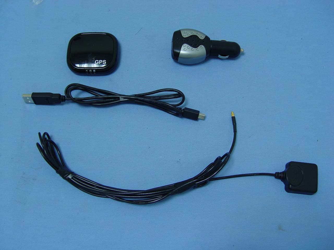
Aug 30, 2006Bluetooth GPS Receiver
Equipment Class
DSS - Part 15 Spread Spectrum Transmitter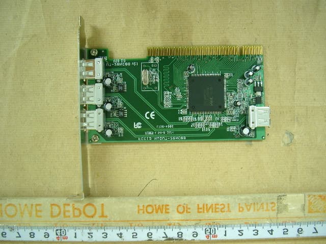
NUOUT-20NC08
Jun 25, 2002USB 2.0 PCI Card
Equipment Class
JBP - Part 15 Class B Computing Device Peripheral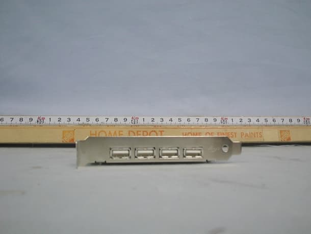
NUOUT-20NC01
Jul 16, 2001USB 2.0 PCI Card
Equipment Class
JBP - Part 15 Class B Computing Device Peripheral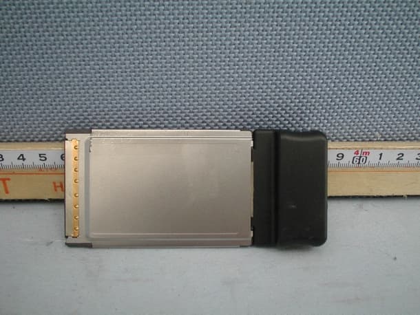
NUOUT-T2PC
May 08, 2001IEEE 1394 Card Bus With PCMCIA Interface
Equipment Class
JBP - Part 15 Class B Computing Device Peripheral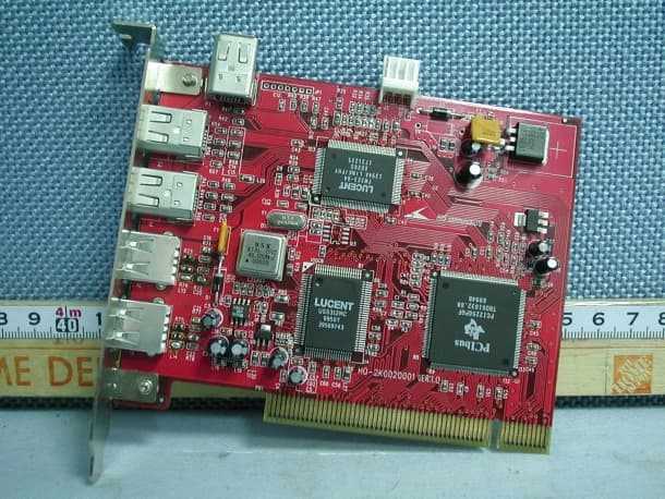
NUOUT-FU32
May 07, 2001IEEE 1394 and USB Combo Card
Equipment Class
JBP - Part 15 Class B Computing Device Peripheral