NUVMT53H749HEADSET TRANSCEIVER, 49 MHz
Aearo Company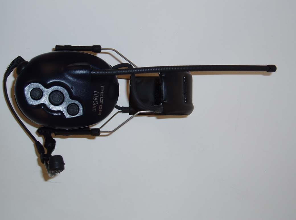
Click to zoom
Application Details
- Equipment Class
- DXT - Part 15 Low Power Transceiver, Rx Verified
- Date of Grant
- Jun 29, 2004
- Application Purpose
- Original Equipment
- Date of Application
- Jun 29, 2004
- Equipment Note
- HEADSET TRANSCEIVER, 49 MHz
- Frequency Range
- 49.82000000 - 49.90000000
- Company
- Aearo Company
- Country
- United States
Documents & Files
Document Text
Text extracted from the exhibit documents filed with the FCC. Open a document above to read the original.
Users Manual
POWERCOM PLUS POWERCOM LITECOM ENG Instruction manual ESP Instrucciones de uso FRA Mode d’emploi PowerCom Plus PowerCom Lite-Com PowerCom Plus 462-467 MHz (FRS) 14 channels, 38 sub-channels FCC and Industry Canada (IC) approved Model Numbers: MT53H7A4610 Headband model MT53H7B4610 Neckband model MT53H7P3E4610 Slotted hardhat mount model PowerCom 462-467 MHz (FRS) 14 channels, 38 sub-channels FCC and Industry Canada (IC) approved Model Numbers: MT53H7A4600 Headband model MT53H7B4600 Neckband model MT53H7P3E4600 Slotted hardhat mount model LiteCom 49.830-49.890 MHz 5 channels FCC and Industry Canada (IC) approved Model Numbers: MT53H7A4900 Headband model MT53H7B4900 Neckband model MT53H7P3E4900 Slotted hardhat mount model PELTOR 2-WAY RADIO HEADSETS THANK-YOU for your purchase of Peltor’s latest self-contained 2-way radio headset product. PowerCom Plus, PowerCom, and LiteCom all offer reliable, efficient communication between two or more people in noisy environments. Although these products are very user-friendly, please take the time to read this instruction manual carefully to ensure proper set-up and use of all features • PowerCom Plus and PowerCom are 2-way radio headsets pre-programmed to 22 or 14 channels in the FRS and/or GMRS frequency band with 38 privacy sub-channels. These units have up to 0.15 watts of transmitting power with a range of 2 km outdoors. The range will vary depending on local surrounding environmental conditions. • LiteCom is a 2-way radio headset pre-programmed to 5 channels in the 49 MHz frequency band. This unit has up to 0.1 watts of transmitting power with a range of 100M outdoors. The range will vary depending on local surrounding environmental conditions. • The PowerCom Plus/PowerCom headsets will not communicate with the LiteCom headsets. However, PowerCom Plus headsets will communicate with PowerCom headsets. • All models feature advanced ghost voice confirmations of mode and level selections. As an added bonus, the ghost voices are selectable by the user in every model. Language options are English, French or Spanish. Depending on the product purchased, they will communicate with other similar license-free radio products in the FRS, GMRS and 49 MHz frequencies. These devises comply with part 15 of the FCC rules and regulations. Operation of these devices are subject to the following two conditions: 1) These devises may not cause harmful interference, and 2) These devises must accept any interference received, including interference that may cause undesired operation Headset basics.... Refer to figure H. 1. (MT53H7A****) Wide padded headband – for over-the-head use (MT53H7B****) Neckband - for use under a hardhat (MT53H7P3E****) Slotted hardhat mount – snaps into slots of hardhats 2. Stainless steel headband wires – special bending processes ensure an even distribution of pressure around the ears. 3. Guide arms – slide assembly for easy height adjustment. 4. Ear seals – foam with liquid bladder for all day comfort, built-in pressure-relief canals ensure low pressure and effective sealing. See page 12 for replacements. 5. Antenna – flexible with fixed mount design and high reception quality 6. Audio jack - for external audio accessories including 2-way radios, cell phones, personal entertainment devises, see page 13 7. Battery cover – requires 2 standard 1.5-volt AA alkaline batteries, optional rechargeable battery pack available, see page 12 8. Key pad - for easy changing of modes, settings and levels. 9. Lip microphone – quick positioning metal boom assembly with an electret noise canceling condenser, see page 12 for replacements. 10. Cup microphones – amplify and reproduce in stereo inside the headset ambient noises and voices allowing the user to be fully aware of surrounding environment. (Only available with PowerCom Plus models). See page 12 for foam replacements. 11. Headset Push-To-Talk (PTT) – will key up lip microphone and activate the radio inside headset to start transmitting. 6 1 2 3 4 5 7 11 10 (H) 9 8 Getting Started... BATTERIES Open the battery cover (#7, Fig. H) and place two 1.5 Volt AA size batteries inside the compartment. Ensure that the + and – poles of the batteries are in the correct positions (refer to figure inside the battery cover). The headset is polarity protected in the event batteries are incorrectly inserted. When the batteries get low in power, a voice message saying “low battery” will be heard inside the headset. This message will be repeated in 2 minute intervals until the batteries are completely depleted, at which point the headset will have a voice confirmation saying “battery empty” and will shut off. Note(s): 1) Battery life span/operating time varies greatly depending on the type of batteries and how the headset is used. For example, with an alkaline battery with at least 2000 mAh, the operating time in low-power mode is about 30 hours at 10 % transmission, 10 % reception and 80 % stand-by. In high-power mode, the operating time under the same conditions decreases by about 10 %. At 20 % transmission, 20 % reception and 60% stand-by, the operating time is about 20 hours. 2) The headset has an automatic shut-off feature to save on batteries. It will turn itself off automatically after 2 hours if one of the following keys is not activated in that timeframe: (0) (+) (-) (PTT/VOX). A triple tone signal will be emitted every 30 seconds for 5 minutes prior to final shut down. ADJUSTING THE CUPS FOR FIT (Fig. J) 1. The cup guide arms (#3, fig H) slide up and down the metal wires. 2. For headband and neckband models, place the headset on your head, with one hand, hold the band (#1, fig H) in place and with the other slowly move the cup up/down the wire arms until they are in the comfortable and snug fit position. 3. For harthat mount position (fig. K) snap the headset helmet attachment into the slot of the helmet. Place the hardhat with headsets in place on your head and refer to 2. above for cup placement instructions. Th…
Text truncated - open the document above for the full version.
External Photos
ANNEX 2 – EXTERNAL PHOTOGRAPHS Aearo Company Transceiver, Model Peltor LiteCom FCC ID: NUVMT53H749 IC: 4406A-MT53H749 A2 - 1 ANNEX 2 – EXTERNAL PHOTOGRAPHS Aearo Company Transceiver, Model Peltor LiteCom FCC ID: NUVMT53H749 IC: 4406A-MT53H749 A2 - 2 ANNEX 2 – EXTERNAL PHOTOGRAPHS Aearo Company Transceiver, Model Peltor LiteCom FCC ID: NUVMT53H749 IC: 4406A-MT53H749 A2 - 3 ANNEX 2 – EXTERNAL PHOTOGRAPHS Aearo Company Transceiver, Model Peltor LiteCom FCC ID: NUVMT53H749 IC: 4406A-MT53H749 A2 - 4 ANNEX 2 – EXTERNAL PHOTOGRAPHS Aearo Company Transceiver, Model Peltor LiteCom FCC ID: NUVMT53H749 IC: 4406A-MT53H749 A2 - 5
ID Label/Location Info
FCC_49_label (1163x915x16M jpeg)
Internal Photos
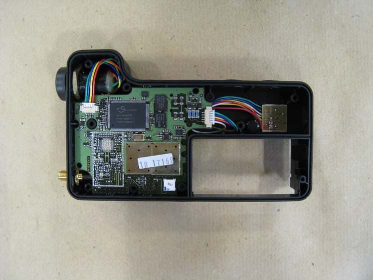
ANNEX 3 – INTERNAL PHOTOGRAPHS Aearo Company Transceiver, Model Peltor LiteCom FCC ID: NUVMT53H749 IC: 4406A-MT53H749 A2 - 1 ANNEX 3 – INTERNAL PHOTOGRAPHS Aearo Company Transceiver, Model Peltor LiteCom FCC ID: NUVMT53H749 IC: 4406A-MT53H749 A2 - 2 ANNEX 3 – INTERNAL PHOTOGRAPHS Aearo Company Transceiver, Model Peltor LiteCom FCC ID: NUVMT53H749 IC: 4406A-MT53H749 A2 - 3 ANNEX 3 – INTERNAL PHOTOGRAPHS Aearo Company Transceiver, Model Peltor LiteCom FCC ID: NUVMT53H749 IC: 4406A-MT53H749 A2 - 4 ANNEX 3 – INTERNAL PHOTOGRAPHS Aearo Company Transceiver, Model Peltor LiteCom FCC ID: NUVMT53H749 IC: 4406A-MT53H749 A2 - 5
Test Report
Headset Transceiver, 49 MHz Model No.: Peltor LiteCom FCC ID: NUVMT53H749 Applicant: Aearo Company 5457 W.79 th Street Indianapolis, INDIANA USA, IN 46268 In Accordance With Federal Communications Commission (FCC) Part 15, Subpart C, Section 15.235 Intentional Radiators in the Band 49.82 – 49.90 MHz UltraTech's File No.: TLT-006FCC15C235 This Test report is Issued under the Authority of Tri M. Luu, Professional Engineer, Vice President of Engineering UltraTech Group of Labs Date: June 23, 2004 Report Prepared by: Anca Dobre Issued Date: June 23, 2004 Tested by: Hung Trinh, RFI Technician Test Dates: April 18 – May 13, 2004 The results in this Test Report apply only to the sample(s) tested, and the sample tested is randomly selected. This report must not be used by the client to claim product endorsement by NVLAP or any agency of the US Government. UltraTech 3000 Bristol Circle, Oakville, Ontario, Canada, L6H 6G4 Tel.: (905) 829-1570 Fax.: (905) 829-8050 Website: www.ultratech-labs.com , Email: [email protected], Email: [email protected] 2 31040/SIT C-1376 46390-2049 200093-0 SL2-IN-E-1119R 00-034 FCC Part 15, Subpart C, Section 15.235, INTENTIONAL RADIATORS Contents i Headset Transceiver, 49 MHz; Model: Peltor LiteCom FCC ID: NUVMT53H749 ULTRATECH GROUP OF LABS File #: TLT-006FCC15C235 3000 Bristol Circle, Oakville, Ontario, Canada L6H 6G4 June 21, 2004 Tel. #: 905-829-1570, Fax. #: 905-829-8050, Email: [email protected] , Website: http://www.ultratech-labs.com All test results contained in this engineering test report are traceable to National Institute of Standards and Technology (NIST) TABLE OF CONTENTS EXHIBIT 1. SUBMITTAL CHECK LIST .............................................................................................................. 1 EXHIBIT 2. INTRODUCTION.............................................................................................................................. 2 2.1. SCOPE ........................................................................................................................................................ 2 2.2. RELATED SUBMITTAL(S)/GRANT(S) ....................................................................................................... 2 2.3. NORMATIVE REFERENCES .....................................................................................................................2 EXHIBIT 3. PERFORMANCE ASSESSMENT ................................................................................................... 3 3.1. CLIENT INFORMATION ............................................................................................................................. 3 3.2. EQUIPMENT UNDER TEST (EUT) INFORMATION .................................................................................. 3 3.3. EUT’S TECHNICAL SPECIFICATIONS...................................................................................................... 4 3.4. LIST OF EUT’S PORTS .............................................................................................................................. 5 3.5. ANCILLARY EQUIPMENT .......................................................................................................................... 5 3.6. BLOCK DIAGRAM OF TEST SETUP.......................................................................................................... 5 EXHIBIT 4. EUT OPERATING CONDITIONS AND CONFIGURATIONS DURING TESTS ............................. 6 4.1. CLIMATE TEST CONDITIONS ................................................................................................................... 6 4.2. OPERATIONAL TEST CONDITIONS & ARRANGEMENT FOR TESTS .................................................... 6 EXHIBIT 5. SUMMARY OF TEST RESULTS..................................................................................................... 7 5.1. LOCATION OF TESTS................................................................................................................................ 7 5.2. APPLICABILITY & SUMMARY OF EMC EMISSION TEST RESULTS....................................................... 7 5.3. MODIFICATIONS INCORPORATED IN THE EUT FOR COMPLIANCE PURPOSES ............................... 7 EXHIBIT 6. MEASUREMENTS, EXAMINATIONS & TEST DATA FOR EMC EMISSIONS ............................. 9 6.1. TEST PROCEDURES ................................................................................................................................. 9 6.2. MEASUREMENT UNCERTAINTIES .......................................................................................................... 9 6.3. MEASUREMENT EQUIPMENT USED ....................................................................................................... 9 6.4. METHOD OF MEASUREMENTS................................................................................................................ 9 6.5. ESSENTIAL/PRIMARY FUNCTIONS AS DECLARED BY THE MANUFACTURER .................................. 9 6.6. ANTENNA REQUIREMENTS [§15.203]..................................................................................................... 9 6.7. 26 dB BANDWIDTH [§ 2.1049].................................................................................................................. 10 6.8. TRANSMITTER RADIATED EMISSIONS @ 3 METERS [§§ 15.235(a), (b), 15.209 & 15.205] ................ 12 EXHIBIT 7. MEASUREMENT UNCERTAINTY ................................................................................................ 20 7.1. RADIATED EMISSION MEASUREMENT UNCERTAINTY ...................................................................... 20 FCC Part 15, Subpart C, Section 15.235, INTENTIONAL RADIATORS Page 1 Headset Transceiver, 49 MHz; Model No.: Peltor LiteCom FCC ID: NUVMT53H749 ULTRATECH GROUP OF LABS File #: TLT-006FCC15C235 3000 Bristol Circle, Oakville, Ontario, Canada L6H 6G4 June 21, 2004 Tel. #: 905-829-1570, Fax. #: 905-829-8050, E…
Text truncated - open the document above for the full version.
Contact Information
Applicant
Mike Cimino(Marketing Director)
Test Firm
UltraTech Engineering Labs Inc.Victor Kee
Technical Specifications
| # | Rule Parts | Frequency Range | Power Output |
|---|---|---|---|
| 1 | 15C | 49.82 MHz - 49.9 MHz | - |
Other Applications from Aearo Company
NUVP840
Apr 26, 2011Peltor P840 DECT-Com II
Equipment Class
PUT - Part 15 Unlicensed PCS portable Tx worn on body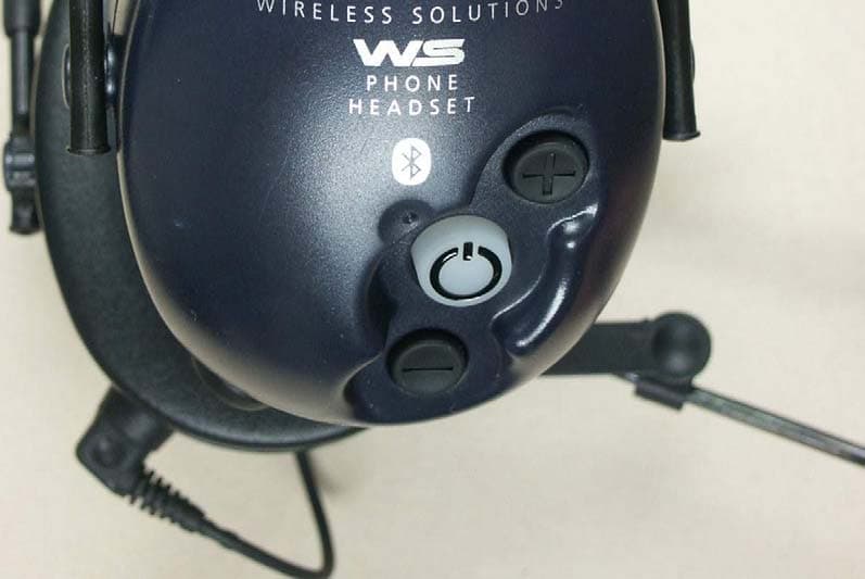
NUVMT53H7WS
Oct 06, 2004PeltorWS
Equipment Class
DSS - Part 15 Spread Spectrum Transmitter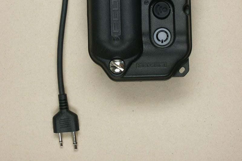
NUVFL6000WS
Sep 30, 2004PeltorWS
Equipment Class
DSS - Part 15 Spread Spectrum Transmitter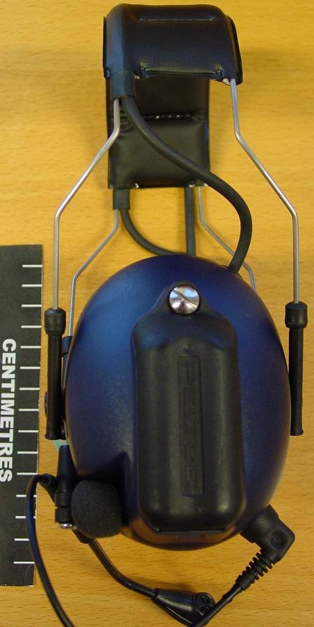
NUVMT53H74
Feb 18, 2004GMRS / FRS COMBINATION TRANSCEIVER
Equipment Class
FRE - Part 95 Family Radio Ear Held Transmitter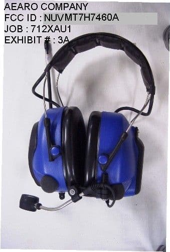
NUVMT7H7460A
Nov 27, 2001Family Radio Body Worn TX
Equipment Class
FRT - Part 95 Family Radio Body Worn Transmitter