NUVMT7H7460AFamily Radio Body Worn TX
Aearo Company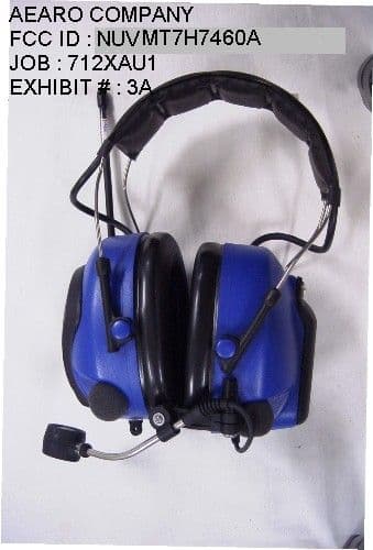
Click to zoom
Application Details
- Equipment Class
- FRT - Part 95 Family Radio Body Worn Transmitter
- Date of Grant
- Nov 27, 2001
- Application Purpose
- Original Equipment
- Date of Application
- Nov 27, 2001
- Equipment Note
- Family Radio Body Worn TX
- Frequency Range
- 462.56250000 - 467.71250000
- Company
- Aearo Company
- Country
- United States
Documents & Files

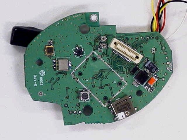
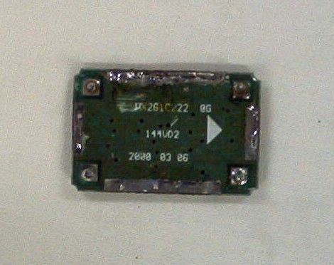

Document Text
Text extracted from the exhibit documents filed with the FCC. Open a document above to read the original.
Operational Description
ONE Reference Create Date Issue Date Issue Doc # Page mah 011028 011102 1 P520_FRS_Technical_Description.doc Page 1 of 11 We reserve all rights to this document and the information contained therein. Reproduction, use or loc:11/13/01 11:59 AM, 712x-8-circ des tech descr align pro.doc disclosure to third parties without express written authority from the proprietors is strictly prohibited. Lite Com II FRS (P520 FRS) Technical Description 1 Overview LiteComII is a complete Active Hearing Protection Headset with built in medium range Communication Radio working in the US FRS (Family Radio Service) band. It has an External I/O port that allows connection to: • Most types of Land Mobile Radios. • Entertainment sources like portable CD's, Walkman etc. • GSM and other Analog or digital cellular phones The user interface is based on five levels with varying capability: Voice message. This level is used in normal operation. It gives brief info and feedback to allow unambiguous operation with your hands only. LCD, Operation This level gives the user more information at the expense of taking the unit off to see the LCD. LCD, Configuration This level enables the user to configure a number of Set-up parameters without a PC. PC, Set-up. Using a level 2 password, this level gives total control of all Set-up parameters. PC, Service Using a level 3 password, this level allows total control of all Set-up parameters and all adjustment points. The mechanical parts are in line with other high end Peltor products. 1.1 Development phase The electronics was developed by ONE (O-Network Engineering AB) for Peltor. The development project was based on the P520 LPD radio for Europe 2 Documentation The documentation is created by Peltor and ONE (O-Network Engineering AB). The documentation builds on the P520 LPD version. Decumentation CD (pdf format): "LiteComII documentation. Up to Revision 1.1 2000-04-20" You need the Acrobat Reader 4.0 or later to read them. The most documentation specific to the FRS version are the circuit diagram and layout etc for the Rf board. The software is identical except for the RF channel data. 2.1 Revision History Date H/W Rev S/W Rev ECN Notes There are no revisions yet. AEARO COMPANY FCC ID : NUVMT7H7460A JOB : 712XAU1 EXHIBIT : 8 ONE Reference Create Date Issue Date Issue Doc # Page mah 011028 011102 1 P520_FRS_Technical_Description.doc Page 2 of 11 We reserve all rights to this document and the information contained therein. Reproduction, use or loc:11/13/01 11:59 AM, 712x-8-circ des tech descr align pro.doc disclosure to third parties without express written authority from the proprietors is strictly prohibited. The details of the various revisions can be found in the documents and ECN's. 2.2 Support documents On the P520 LPD CD there are a large number of support documents: • Datasheets for all major components in the directory "Component Data" • Regulatory documents in the directory "Approval" • Application related information in the directory "Support" Most of these are valid also for the FRS version. 2.3 LiteComII Utility Software These can be found in the directory "LiteComII Utilities" 2.4 Block Diagram The principle of the set can be seen in the Block Diagram P520FRSB_SCS.PDF. This can be found in the directories R1.0 and R1.1. The block diagram is detailed down to the major parts and signal names. To fully understand the design it is recommended that a hierarchical view is employed: 1. This document is the top level 2. The block diagram is the second level 3. The circuit diagram is the most detailed technical level. 4. The BOM (Bill Of Material) is the most detailed parts level. The design is based on a number of highly integrated IC's that perform the principal functions. Function Major parts • DC/DC Converter U203 MAX1706 • CPU U1 TMP87CH21 • EEPROM U3 24C02/24C16 • Voice message storage U2 ISD1210 • LCD Custom LCD with 1:3 multiplexing. • Baseband processing U13 AKM2344 • VOX U4 LMV321 • Synthesizer U1 TB31202FN and U2 VCO1 • Receiver IF U3 MC3371D • Speaker Amplifier U201,202 MC34119 (2pcs) • Ambient channel gain and AGC U9,12 LMV358 (2pcs) Q4 • Ambient channel volume control U5,8 X9315W (2pcs) • External VOX - • Half Duplex RS232 - • DC Sink - The support functions are then realized by a set of discrete components around these IC's. These are listed in the Block Diagram when they are important for the understanding. Otherwise refer to the circuit diagrams. 2.5 Software The software is documented by a number of documents in the directory "Software". The most important items are: • RS232 Commands 107_doc.pdf • Voice_doc.pdf ONE Reference Create Date Issue Date Issue Doc # Page mah 011028 011102 1 P520_FRS_Technical_Description.doc Page 3 of 11 We reserve all rights to this document and the information contained therein. Reproduction, use or loc:11/13/01 11:59 AM, 712x-8-circ des tech descr align pro.doc disclosure to third parties without express written authority from the proprietors is strictly prohibited. 2.6 Circuit Diagrams The fully detailed circuit diagrams are: • Base Band Board P520C11_SCS.PDF (2 pages) • RF Board PFRSR11a_SCS.PDF (2 pages) They can be found in the directory R1.1 2.7 Assembly drawings. The assembly drawings are: • P980221 (1 page) Wiring Instruction • P980223 (3 pages) Assemble Drawing They can be found in the directory "Assembly" 3 Hardware - Software Relationship An important feature of the LiteComII is the heavy use of software controlled switches and electronic potentiometers. These are used to: • Adjust the unit in production. Examples are Max Modulation, Squelch set-up level etc. • Select operational modes. An example is the switching of the audio signals between Receive and Transmit. • Set the level of most functions. Examples are both the Ambient Volume, Transceiver (Mix) volume and Balance. There are very few normal "mechanical" adjustments of the type found in most sets: • TCXO frequency is set by the trimmer in X2 • The Tx Lo power i…
Text truncated - open the document above for the full version.
Test Report
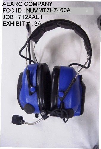
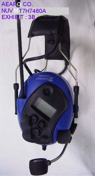
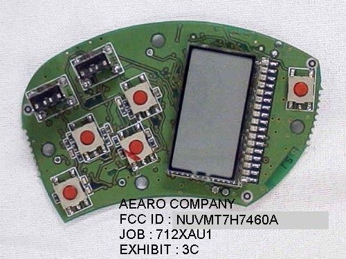
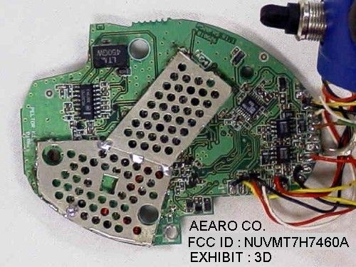
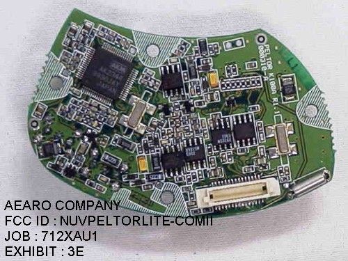
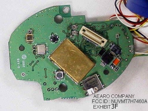
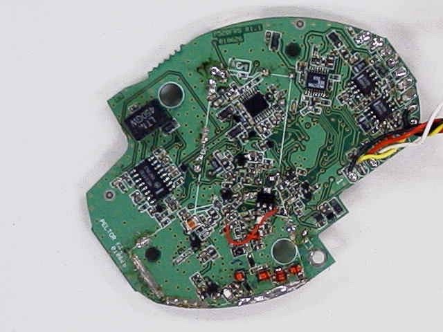
APPLICANT: AERO COMPANY FCC ID: NUVMT7H7460A REPORT #: T:\A\AEARO\712XAU1\712XAU1TestReport.doc TABLE OF CONTENTS LIST TABLE OF CONTENTS LIST APPLICANT: AEARO COMPANY FCC ID: NUVMT7H7460A TEST REPORT: PAGE 1......COVER SHEET - GENERAL INFORMATION & TECHNICAL DESCR. PAGE 2......TECHNICAL DESCRIPTION CONTINUED PAGE 3......RF POWER OUTPUT AND TEST SET UP PAGE 4......MODULATION CHARACTERISTICS PAGE 5......AUDIO FREQUENCY RESPONSE GRAPH PAGE 6......MODULATION LIMITING PLOT PAGE 7......AUDIO LOW PASS FILTER GRAPH PAGE 8......OCCUPIED B/W AND METHOD OF MEASURING OCCUPIED BANDWIDTH PAGE 9......OCCUPIED BANDWIDTH CW PLOT PAGE 10.....OCCUPIED BANDWIDTH PLOT PAGE 11.....FIELD STRENGTH OF SPURIOUS EMISSIONS PAGE 12.....METHOD OF MEASURING RADIATED SPURIOUS EMISSIONS PAGE 13.....FREQUENCY STABILITY PAGE 14.....LIST OF TEST EQUIPMENT EXHIBITS CONTAINING: EXHIBIT 1.........FCC ID LABEL SAMPLE EXHIBIT 2.........SKETCH OF FCC ID LABEL LOCATION EXHIBIT 3A........EXTERNAL PHOTO - FRONT VIEW EXHIBIT 3B........EXTERNAL PHOTO – SIDE VIEW EXHIBIT 3C........INTERNAL PHOTO – COMPONENT VIEW-1 EXHIBIT 3D........INTERNAL PHOTO - COMPONENT VIEW-2 EXHIBIT 3E........INTERNAL PHOTO – COMPONENT VIEW-3 EXHIBIT 3F........INTERNAL PHOTO – SOLDER VIEW EXHIBIT 4.........BLOCK DIAGRAM EXHIBIT 5A-5B.....SCHEMATIC EXHIBIT 6.........USERS MANUAL EXHIBIT 7.........TEST SET UP PHOTO EXHIBIT 8.........TECHNICAL DESCR./CIRCUIT DESCR./ALIGN PROCEDURE APPLICANT: AERO COMPANY FCC ID: NUVMT7H7460A REPORT #: T:\A\AEARO\712XAU1\712XAU1TestReport.doc Page 1 of 14 GENERAL INFORMATION REQUIRED FOR TYPE ACCEPTANCE 2.1033(c)(1)(2)AEARO COMPANY will manufacture the FCCID: NUVMT7H7460A FAMILY RADIO SERVICES 14CHANNEL TRANSCEIVER in quantity, for use under FCC RULES PART 95. The UUT is a PTT Radio with a maximum duty cycle of 50%. AEARO COMPANY 5457 W. 79TH STREET INDIANAPOLIS IN 46268 2.1033 (c) TECHNICAL DESCRIPTION 2.1033(c)(3) Instruction book. A draft copy of the instruction manual is included as EXHIBIT 6. 2.1033(c) (4) Type of Emission: 10K6F3E 95.631 Bn = 2M + 2DK M = 3000 D = 2.3K Bn = 2(3.0)+2(2.3) = 10.6K Authorized Bandwidth 12.5 kHz 2.1033(c)(5) Frequency Range: 1. 462.5625 8. 467.5625 95.627 2. 462.5875 9. 467.5875 3. 462.6125 10. 467.6125 4. 462.6375 11. 467.6375 5. 462.6625 12. 467.6625 6. 462.6875 13. 467.6875 7. 462.7125 14. 467.7125 MHz 2.1033(c)(6)(7) Power Output shall not exceed 0.500 Watts effective 95.639 radiated power. There can be no provisions for 95.649 increasing the power or varying the power. 95.647 The antenna is an integral part to the unit, it cannot be removed without rendering the unit inoperative. In order to remove the antenna the case must unscrewed, then the PCB assemblies must be removed then the antenna can be removed. APPLICANT: AERO COMPANY FCC ID: NUVMT7H7460A REPORT #: T:\A\AEARO\712XAU1\712XAU1TestReport.doc Page 2 of 14 2.1033(c)(8) DC Voltages and Current into Final Amplifier: FINAL AMPLIFIER ONLY Vce 3.0 Volts DC Ice = 0.21A. Pin = .63 Watts 2.1033(c)(9) Tune-up procedure. The tune-up procedure is included in the TECHNICAL DESCRIPTION MANUAL. 2.1033(c)(10) Complete Circuit Diagrams: The circuit diagram is included as EXHIBIT 5A-5B of this report. The block diagram is included as EXHIBIT No. 4 of this report. 2.1033(c)(11) A photograph or a drawing of the equipment identification label is included as EXHIBIT No. 1. 2.1033(c)(12) Photographs(8"X10") of the equipment of sufficient clarity to reveal equipment construction and layout, including meters, labels for controls, including any view under shields - See EXHIBIT’S 3A-3F. 2.1033(c)(13) Digital modulation is not allowed. 2.1033(c)(14) The data required by 2.1046 through 2.1057 is submitted below. APPLICANT: AERO COMPANY FCC ID: NUVMT7H7460A REPORT #: T:\A\AEARO\712XAU1\712XAU1TestReport.doc Page 3 of 14 2.1046(a) RF power output. 95.639 RF power is measured by measuring the radiated power at 3 meters and then replacing the transmitter with a signal generator to determine the effective radiated power. The ERP shall not exceed 0.500 Watts. MEASURED POWER OUTPUT = 0.084 Watts ERP R.F. POWER OUTPUT HP TEST SET UP Spectrum Analyzer TRANSMITTER UNDER TEST WITH INTERNAL ANTENNA <--3.0 meters--> SIGNAL DIPOLE Tuned, Calibrated GENERATOR ANTENNA Antenna which may be raised from 1 to 4 meters above ground and changed in polarization Equipment placed 80cm above ground on a rotatable platform. APPLICANT: AERO COMPANY FCC ID: NUVMT7H7460A REPORT #: T:\A\AEARO\712XAU1\712XAU1TestReport.doc Page 4 of 14 2.1047(a)(b) Modulation characteristics: AUDIO FREQUENCY RESPONSE The audio frequency response was measured in ac- cordance with TIA/EIA Specification 603. The audio frequency response curve is shown on page 5. The audio signal was fed into a dummy microphone circuit and into the microphone connector. The input required to produce 30 percent modulation level was measured. 2.1047(b) Audio input versus modulation The audio input level needed for a particular per- percentage of modulation was measured in accor- dance with TIA/EIA Specification 603. The audio input curves versus modulation are shown on page 6. Curves are provided for audio input frequencies of 300, 1000, and 3000 Hz. 95.637(b) Post Limiter Filter The filter must be between the modulation limiter and the modulated stage. At any frequency between 3 & 20KHz the filter must have an attenuation of 60log (f/3) greater that the attenuation at 1KHz. See the plot on page 7. APPLICANT: AERO COMPANY FCC ID: NUVMT7H7460A REPORT #: T:\A\AEARO\712XAU1\712XAU1TestReport.doc Page 5 of 14 AUDIO FREQUENCY RESPONSE GRAPH Input level dbmV 0.0 5.0 10.0 15.0 20.0 25.0 30.0 35.0 40.0 45.0 50.0 100100010000 Frequency Hz Level dBmV Input level dbmV APPLICANT: AERO COMPANY FCC ID: NUVMT7H7460A REPORT #: T:\A\AEARO\712XAU1\712XAU1TestReport.doc Page 6 of 14 MODULATION LIMITING GRAPH Maximum Deviation vs frequency 0 500 1000 1500 2000 2500 100100010000100000 Modulation Frequency Deviation in Hz Deviation The Mic level 0f 62mV …
Text truncated - open the document above for the full version.
Contact Information
Applicant
Mike Cimino(Marketing Director)
Test Firm
Timco Engineering, Inc.S Sanders
Technical Specifications
| # | Rule Parts | Frequency Range | Power Output | Emission | Tolerance |
|---|---|---|---|---|---|
| 2 | 95B | 462.5625 MHz - 467.7125 MHz | 33.00 mW | 10K6F3E | 2.5 ppm |
Other Applications from Aearo Company
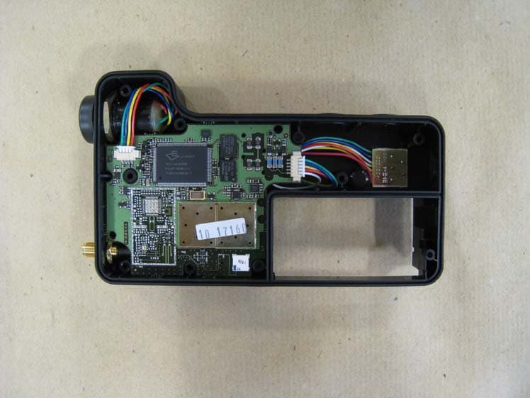
NUVP840
Apr 26, 2011Peltor P840 DECT-Com II
Equipment Class
PUT - Part 15 Unlicensed PCS portable Tx worn on body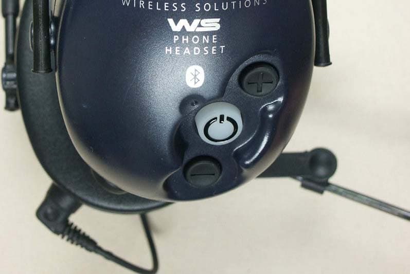
NUVMT53H7WS
Oct 06, 2004PeltorWS
Equipment Class
DSS - Part 15 Spread Spectrum Transmitter
NUVFL6000WS
Sep 30, 2004PeltorWS
Equipment Class
DSS - Part 15 Spread Spectrum Transmitter
NUVMT53H749
Jun 29, 2004HEADSET TRANSCEIVER, 49 MHz
Equipment Class
DXT - Part 15 Low Power Transceiver, Rx Verified
NUVMT53H74
Feb 18, 2004GMRS / FRS COMBINATION TRANSCEIVER
Equipment Class
FRE - Part 95 Family Radio Ear Held Transmitter