NVJAR5700DDigital Processing Communications Receiver
AOR USA Inc.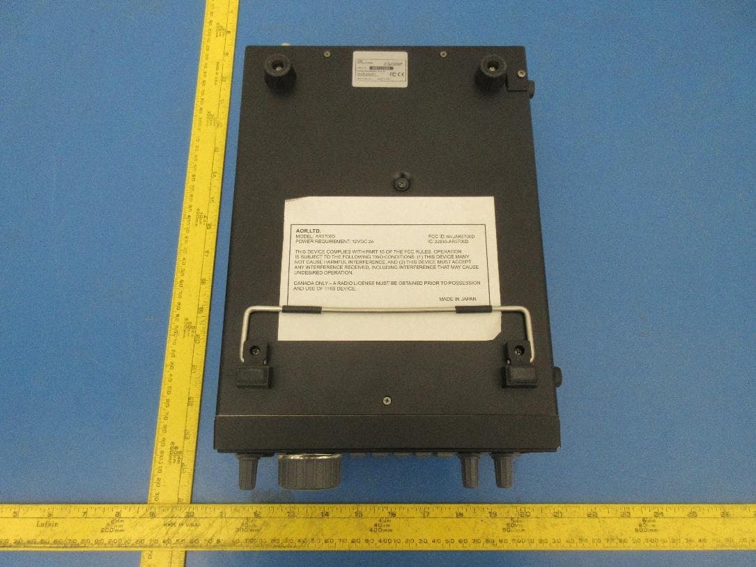
Click to zoom
Application Details
- Equipment Class
- CSR - Scanning Receiver
- Date of Grant
- Apr 21, 2020
- Application Purpose
- Original Equipment
- Date of Application
- Apr 21, 2020
- Equipment Note
- Digital Processing Communications Receiver
- Frequency Range
- 894.00000000 - 960.00000000
- Company
- AOR USA Inc.
- Country
- United States
Documents & Files
Document Text
Text extracted from the exhibit documents filed with the FCC. Open a document above to read the original.
Users Manual
® DIGITAL COMMUNICATIONS RECEIVER AR5700D Operating manual AOR, LTD. Authority On Radio Communications INTRODUCTION Thank you for purchasing the AR5700D. AR5700D is a high-end table-top receiver with wideband coverage between 9kHz and 3.7GHz. It supports a variety of digital, as well as analog modes. Some of its outstanding features are: 1)Digital signal processing: Input signals after the 45.05MHz IF are converted from analog to digital by a DSP processor. There is no AGC in the analog processing unit, as all processing, including AGC, is done by DSP. 2)High-performance analog front-end: Analog signal processing is performed by a computer simulated, high-performance distribution constant filter . 3)DDS local oscillator: Instead of the conventional PLL method, the first local frequency is produced by direct digital synthesis. That method allows frequency switching at high speed. 4)IF output: An analog IF of 15MHz (+/-7.5MHz) bandwdth is output. 5)Digital I/Q output: A digital I/Q signal of 0.9MHz is output via a USB 2.0 interface. 6)High precision frequency reference: 0.01ppm frequency stability of the 10MHz internal master oscillator is achieved when using the optiona GPS receiver unit. 7)FFT analizer: Thanks to the onboard FFT processor, 10MHz wide spectrum data can be output at high speed via serial. 8)Multi-mode digital voice demodulation: D-STAR, YAESU, ALINCO, D-CR, NXDN, P25, dPMR, DMR, Mototrbo, TETRA . (Mode dependant restrictions apply) 9)Video demodulation By connecting and external TV monitor, it is possible to demodulate the signal of FM modulation security cameras and analog TV broadcasts. When you connect the TV monitor, you can check the demodulated video. Not compatible with digital terrestrial television. 10)Simultaneous monitoring 2 band reception, offset reception, triple reception (restrictions apply). 11) SD card slot You can record the received audio, analog and decoded digital, as well as logs. 12) 12kHz analog I/Q output Allows DRM broadcasts decoding via a PC and dedicated 3 rd party software. 13) HF direct sampling When receiving HF signals, the signals are converted directly to digital without entering the mixer. This allows very good linearity characteristics. Please read this operating manual carefully. This information will allow you to enjoy maximum performance from your receiver. We sincerely hope that the AR5700D will be your monitoring companion for many years to come. All product names referenced herein are trademarks of their respective manufacturers. Marks such as TM and ® symbols are omitted in the body of the text. 1 TABLE OF CONTENTS INTRODUCTION......................................................................................1 TABLE OF CONTENTS...............................................................................2 SAFETY PRECAUTIONS.............................................................................3 1. Supplied items.................................................................................4 2. Front/rear panel description.............................................................5 2.1. Front panel.................................................................................5 2.2. Rear panel................................................................................11 3. Basic operation..............................................................................13 3.1. Connecting power......................................................................13 3.2. Power on/off.............................................................................13 3.3. Connecting and selecting an antenna............................................13 3.4. Volume.....................................................................................14 3.5. Frequency input.........................................................................14 3.6. Receive mode and IF filter bandwidth...........................................14 3.7. Squelch....................................................................................16 3.8. Tuning step...............................................................................16 3.9. Step-adjust...............................................................................17 4. Advanced functions........................................................................18 5. System settings..............................................................................22 6. Receiver data backup and restore...................................................24 7. Specifications.................................................................................26 2 SAFETY PRECAUTIONS DO NOT operate the receiver near unshielded electrical blasting caps or in an explosive atmosphere. This could cause an explosion and death. DO NOT operate the receiver with a headset or other audio accessories at high volume levels. If you experience a ringing in your ears, reduce the volume or discontinue use. DO NOT directly apply AC power to the DC socket on the receiver rear panel. This could cause a fire or damage the receiver. DO NOT apply more than 16 V to the DC socket on the receiver rear panel. This could cause a fire or damage the receiver. DO NOT reverse the DC power cable polarity. This could cause a fire or damage the receiver. DO NOT let metal, wire or other objects contact the inside of the receiver, or make incorrect contact with connectors on the rear panel. This could cause an electric shock or damage the receiver. DO NOT operate or touch the receiver with wet hands. This could cause an electric shock or damage to the receiver. Immediately turn OFF the receiver power and remove the power cable from the receiver if it emits an abnormal odor, sound or smoke. Contact your AOR dealer or distributor for advice. DO NOT put the receiver on an unstable place where the receiver may suddenly move or fall. This could cause an injury or damage the receiver. DO NOT operate the receiver during a lightning …
Text truncated - open the document above for the full version.
Cover Letter(s)
QA-FR-172-A FCC Confidential Authorization 2019/09/18 FEDERAL COMMUNICATIONS COMMISSIONS Authorization and Evaluation Division 7435 Oakland Mills Road Columbia, MD 21046 Subject: Confidentiality Request regarding application for certification of FCC ID: NVJAR5700D In accordance with Sections 0.457 and 0.459 of the Commission’s Rules,AOR U.S.A., Inc.hereby requests long-term confidential treatment of information accompanying this application as outlined below: Block Diagram Schematics Operation Description As well as short-term (45 days) confidential treatment of information accompanying this application as outlined below: Internal Photos User’s Manual External Photos Test Set-up Photos The above materials contain proprietary and confidential information not customarily released to the public. The public disclosure of these materials provides unjustified benefits to its competitors in the market. Sincerely, AOR U.S.A., INC. Phone: (319)787-8615, Fax: (310)787-8619 Email: [email protected] AOR U.S.A., INC. 426 West Taft Ave., Orange, CA. 92865-4296, U.S.A. Phone: +1-310-787-8615 Fax: +1-310-787-8619
External Photos
AOR USA, INC. FCC ID: NVJAR5700D, IC: 22833-AR5700D EUT External Photographs 1.1 EUT – Top View 1.2 EUT – Bottom View AOR USA, INC. FCC ID: NVJAR5700D, IC: 22833-AR5700D 1.3 EUT – Front View 1.4 EUT – Rear View AOR USA, INC. FCC ID: NVJAR5700D, IC: 22833-AR5700D 1.5 EUT – Right Side View 1.6 EUT – Left Side View
ID Label/Location Info
Label and Label Location EUT Rear View
Test Report
Note: This test report was prepared for the customer shown above and for the device described herein. It may not be duplicated or used in part without prior written consent from Bay Area Compliance Laboratories Corp. This test report shall not be used by the customer to claim product certification, approval, or endorsement by A2LA or any agency of the United States Government or any foreign government. * This test report may contain data and test methods that are not covered by BACL’s scope of accreditation as of the test report date shown above. These items are marked within the test report text with an asterisk “*” FCC PART 15 SUBPART B CLASS B TEST REPORT For AOR USA, Inc. 426 West Taft Ave. Orange, CA 92865, USA FCC ID: NVJAR5700D Model: AR5700D R e p o r t T y p e : O r i g i n a l R e p o r t P r o d u c t T y p e : D i g i t a l C o m m u n i c a t i o n s R e c e i v e r Prepared By Steven Lianto Test Engineer Report Number R1908305 Report Date 2020-04-13 Reviewed By Shoaib Khan EMC Lead Bay Area Compliance Laboratories Corp. 1274 Anvilwood Ave Sunnyvale, CA 94089, USA Tel: (408) 732-9162, Fax: (408) 732 9164 AOR USA, Inc. FCC ID: NVJAR5700D Report Number: R1908305 Page 2 of 69 FCC 15B Test Report TABLE OF CONTENTS 1 GENERAL INFORMATION ....................................................................................................................................... 5 1.1 GENERAL STATEMENTS ........................................................................................................................................... 5 1.2 PURPOSE .................................................................................................................................................................. 5 1.3 AGENT FOR THE RESPONSIBLE PARTY ..................................................................................................................... 6 1.4 RESPONSIBLE PARTY ............................................................................................................................................... 6 1.5 PRODUCT DESCRIPTION OF THE EQUIPMENT UNDER TEST (EUT) ............................................................................ 6 1.6 MECHANICAL DESCRIPTION OF THE EUT ................................................................................................................ 6 1.7 EUT INPUT POWER .................................................................................................................................................. 6 1.8 RELATED SUBMITTAL(S)/GRANT(S) ........................................................................................................................ 6 1.9 TEST FACILITY REGISTRATIONS .............................................................................................................................. 7 1.10 TEST FACILITY ACCREDITATIONS ............................................................................................................................ 7 1.11 MEASUREMENT UNCERTAINTIES ........................................................................................................................... 10 2 EUT TEST CONFIGURATION ................................................................................................................................ 12 2.1 JUSTIFICATION ....................................................................................................................................................... 12 2.2 EUT EXERCISE SOFTWARE .................................................................................................................................... 12 2.3 BACL EMI MEASUREMENT SOFTWARE................................................................................................................ 12 2.4 EQUIPMENT MODIFICATIONS ................................................................................................................................. 12 2.5 SPECIAL EQUIPMENT ............................................................................................................................................. 12 2.6 EUT MODE OF OPERATION ................................................................................................................................... 12 2.7 METHOD OF MONITORING ..................................................................................................................................... 12 2.8 LOCAL SUPPORT EQUIPMENT ................................................................................................................................ 13 2.9 EUT INTERNAL CONFIGURATIONS ........................................................................................................................ 13 2.10 EXTERNAL I/O CABLING LIST AND DETAILS ......................................................................................................... 13 2.11 EUT POWER SUPPLY LIST AND DETAILS ............................................................................................................... 13 3 SUMMARY OF TEST RESULTS ............................................................................................................................. 14 4 FCC 15B §15.107 – CONDUCTED EMISSIONS ..................................................................................................... 15 4.1 APPLICABLE STANDARD ........................................................................................................................................ 15 4.2 EUT SETUP............................................................................................................................................................ 16 4.3 TEST PROCEDURE .................................................................................................................................................. 16 4.4 TEST SETUP BLOCK DIAGRAM ......................................................................................…
Text truncated - open the document above for the full version.
Test Setup Photos
AOR USA, INC. FCC ID: NVJAR5700D, IC: 22833-AR5700D Test Setup Photographs 1.1 Conducted Emissions Low Band, AC Line, Front View Low Band, AC Line, Side View AOR USA, INC. FCC ID: NVJAR5700D, IC: 22833-AR5700D Mid and High Bands, AC Line, Front View Mid and High Bands, AC Line, Side View AOR USA, INC. FCC ID: NVJAR5700D, IC: 22833-AR5700D 1.2 Radiated Emissions All Bands, 30 MHz to 1000 MHz, Front View Low Band, 30 MHz to 1000 MHz, Rear View AOR USA, INC. FCC ID: NVJAR5700D, IC: 22833-AR5700D Mid and High Bands, 30 MHz to 1000 MHz, Rear View All Bands, 1 GHz to 18 GHz, Front View AOR USA, INC. FCC ID: NVJAR5700D, IC: 22833-AR5700D Low Band, 1 GHz to 18 GHz, Rear View Mid and High Bands, 1 GHz to 18 GHz, Rear View AOR USA, INC. FCC ID: NVJAR5700D, IC: 22833-AR5700D All Bands, 18 GHz to 20 GHz, Front View Low Band, 18 GHz to 20 GHz, Rear View AOR USA, INC. FCC ID: NVJAR5700D, IC: 22833-AR5700D Mid and High Bands, 18 GHz to 20 GHz, Rear View
Contact Information
Applicant
Shigeru Takano
Test Firm
Bay Area Compliance Laboratories Corp.Lisa Tang
Technical Specifications
| # | Rule Parts | Frequency Range | Power Output |
|---|---|---|---|
| 3 | 15B | 894 MHz - 960 MHz | - |
Other Applications from AOR USA Inc.
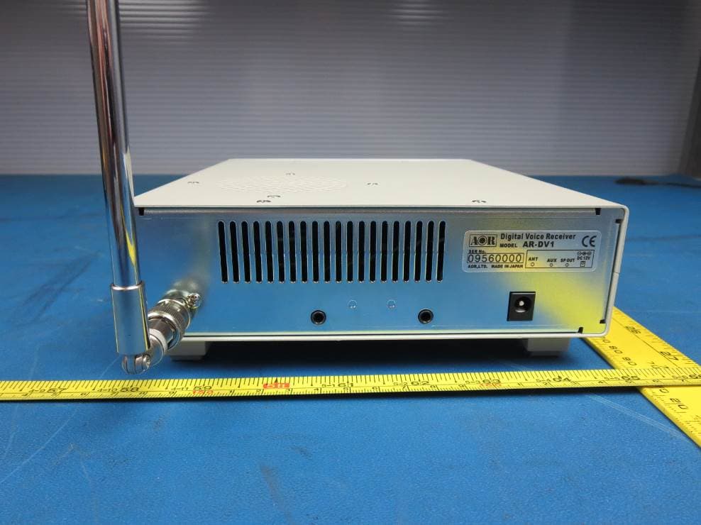
NVJARDV1
May 07, 2015Communications Receiver
Equipment Class
CSR - Scanning Receiver
NVJAR5001D
Aug 21, 2012Digital Processing Communication Receiver
Equipment Class
CSR - Scanning Receiver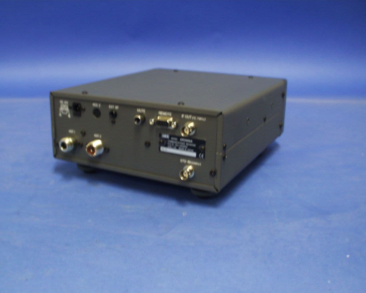
NVJAR5000A
May 31, 2004AR5000A+3B Communications Receiver
Equipment Class
CSR - Scanning Receiver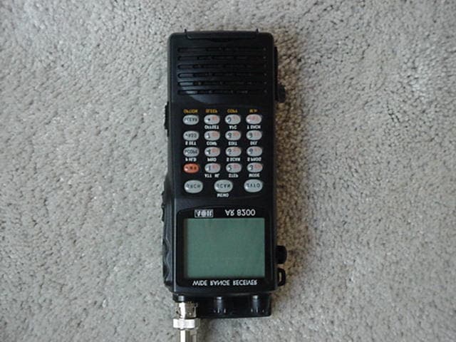
NVJAR8200MK3B
Oct 30, 2002Wide Band Scanning Receiver
Equipment Class
CSR - Scanning Receiver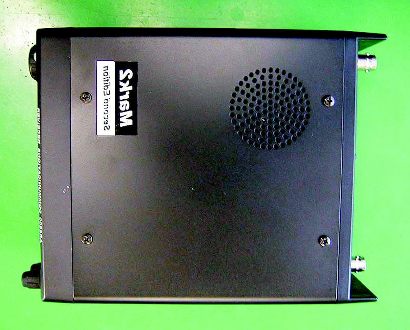
NVJAR8600MK2B
Jul 14, 2002Transportable wide band all mode receiver
Equipment Class
CSR - Scanning Receiver