NVJAR8200MK3BWide Band Scanning Receiver
AOR USA Inc.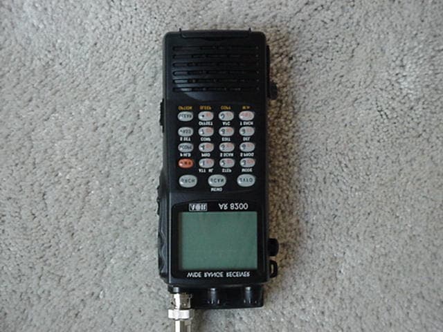
Click to zoom
Application Details
- Equipment Class
- CSR - Scanning Receiver
- Date of Grant
- Oct 30, 2002
- Application Purpose
- Original Equipment
- Date of Application
- Oct 30, 2002
- Equipment Note
- Wide Band Scanning Receiver
- Frequency Range
- 894.00000000 - 960.00000000
- Company
- AOR USA Inc.
- Country
- United States
Documents & Files
Document Text
Text extracted from the exhibit documents filed with the FCC. Open a document above to read the original.
Users Manual
1 (1) AR8200 Index (1) Index ............................................................................................................................1 1-1 Introduction ..................................................................................................................5 1-2 Take care of your radio ................................................................................................5 1-3 Attention while operating .............................................................................................6 1-4 Accessories supplied ...................................................................................................7 1-5 Controls & functions .....................................................................................................8 1-5-1 Keypad .....................................................................................................................9 1-5-2 Summary of keys ......................................................................................................10 1-5-3 Side panel .................................................................................................................15 1-6 Power supply and battery charging .............................................................................16 1-6-1 Internal batteries .......................................................................................................16 1-6-2 Charging the NiCads ................................................................................................18 1-6-3 Cigar lighter lead ......................................................................................................18 1-6-4 Battery considerations ..............................................................................................19 (2) Making the AR8200 ready for operation ...................................................................20 2-1 LCD (Liquid Crystal Display) .......................................................................................20 2-2 Connect the aerial (antenna) .......................................................................................21 2-3 Fit the batteries ............................................................................................................21 2-4 Keypad and knobs... what you need to know ‘most’ ....................................................22 2-4-1 ENTER key ...............................................................................................................22 2-4-2 FUNCTION key .........................................................................................................22 2-4-3 PASS key ..................................................................................................................22 2-4-4 CLEAR key ...............................................................................................................23 2-4-5 MONITOR key ..........................................................................................................23 2-4-6 KEY lock ...................................................................................................................23 (3) Basic manual operation of the receiver ....................................................................24 3-1 Switching On ...............................................................................................................24 3-2 2VFO twin VFO selection ............................................................................................24 3-3 Entering a frequency using the numeric keypad .........................................................26 3-4 Correcting frequency input ..........................................................................................27 3-5 Changing frequency using the Ò and Ú keys ..............................................................28 3-6 Changing frequency using the main dial .....................................................................28 3-7 Changing receive mode ...............................................................................................29 3-7-1 Auto-mode selection .................................................................................................29 3-7-2 Receive mode selection menu .................................................................................29 3-8 Changing tuning STEP size .........................................................................................31 3-9 STEP-adjust ................................................................................................................33 3-9-1 Automatic calculation of step adjust .........................................................................33 3-9-2 Cancelling step adjust ..............................................................................................34 3-9-3 Manual setting of step adjust ....................................................................................34 3-10 FREQUENCY OFFSET ..............................................................................................36 3-10-1 Using pre-programmed frequency offset data ........................................................36 3-10-2 Entering new frequency offset data ........................................................................37 3-11 Attenuator ..................................................................................................................38 3-12 Noise limiter ...............................................................................................................38 3-13 AFC - Automatic Frequency Control ..........................................................................39 (4) VFO enhanced facilities .............................................................................................41 4-1 Quick memories ...........................................................................................................41 4-1-1 Savi…
Text truncated - open the document above for the full version.
Users Manual
51 (5) Memory channels & banks It is convenient to store commonly used frequencies into a memory channel along with mode etc, this saves having to key the data in over and over again. Memory read is very straightforward and quick when compared to re-typing all data. 5-1 Memory channel overview Think of memory channels as pages in a notebook each of which is numbered to identify it. Data may be written to each new page (memory channel) and each page may be overwritten with new data, they can be used over and over again. The AR8200 has 1,000 memory channels in addition to 10 ‘quick memory’ channels and a priority channel. Each memory channel may hold: l one frequency l receive mode l tuning step l step-adjust l frequency offset l attenuator setting l noise limiter status l AFC status l pass status l write protect l text comment of up to 12 characters The alphanumeric comment may be used to ease identification at a later date and to provide text search facilities. The 1,000 memory channels are divided into 20 banks, each initially having 50 channels. The memory banks are identified by letters A, B, C, D, E, F, G, H, I, J (upper case letters) and a, b, c, d, e, f, g, h, i, j (lower case letters) and initially numbered from 00 to 49. Examples are “A00” for the first channel location in memory bank “A” and “A49” for the last memory channel in memory bank “A”. “e15” is the location of memory bank “e” (lower case) channel “15”. During the manufacture and testing of the receiver, various test frequencies may be entered into the receiver’s memory banks so the memory locations may not be completely blank. &Note: Where memory channels and banks are empty the indication “- - -” is often displayed. The stored data may be quickly and easily recalled, changed or deleted using the memory recall, edit and delete facilities. &Note: It is suggested that one or two frequencies be held in each memory bank to make the recalling and scrolling of memory banks fluent, if no data is stored, the AR8200 may take up to 5 or 6 seconds to respond when attempting to change memory bank while the CPU checks for data. Section 5, 5-1 52 Auto-store When shipped from the factory, memory bank “J” is reserved for auto-store of memory channels from search mode. This is a useful facility to quickly build a list of active frequencies. Please refer to section 8-7-5 of this manual for further information regarding AUTO-STORE. Dynamic memory bank resizing The lettered memory banks are regarded as a ‘pair’ making a total of 100 memory channels per bank, initially equally divided between the upper and lower case letters. It is however possible to reallocate the 100 channels in blocks of 10 channels between the same letters A/a, B/b, C,c etc This means that the initial 50/50 may be reallocated as 60/40, 70/30, 80/20, 90/10, or 10/90, 20/80, 30/70, 40/60. This ‘dynamic’ memory reallocation can be useful to optimise the memory layout where a large or small collection of frequencies need to be monitored without unnecessarily wasting memory banks with just a few channels occupied. Write protect It is possible to write protect individual memory channels to prevent accidental deletion, whole memory banks and a ‘global’ write protect facility are also available. Memory backup The data contents of memory and search banks are held in an flash-ROM so that no backup battery or capacitor is required for memory retention. &Note: When the AR8200 is switched OFF, all VFO data will be automatically stored. Should the NiCads (or dry batteries if in use) become completely exhausted, the last stored memory channel or last VFO data ‘may’ be lost if the AR8200 is not powered-down using the key and insufficient power is available to save the data. 5-2 Storing VFO frequencies & data into memory It is possible to save frequencies to the ten quick memories for simple recalling but for longer-term storage, the 1,000 main memory channels offer a better and more flexible system. The process to save a displayed VFO frequency to memory is as follows: a) In VFO mode, select the required frequency, mode, attenuator etc b) to initiate memory write c) Use the keypad, main dial or ÔÒÚ keys to select the desired memory location (BANK and CHANNEL) d) Add a text comment (optional) or delete an existing comment e) Add memory channel write protect (optional) f) Exit the menu to save the data to the specified memory location Lets assume that you wish to store the frequency of 123.500 MHz (with the attenuator off, noise limiter off, AFC off) into memory bank “E” location “25” (E25) while in VFO mode with the text comment of “AIRBAND”. If a mistake is made during programming, the key to abort entry and return to 2VFO mode. a) Start by selecting VFO mode then key in the frequency of 123.500 MHz, “mode and step size” are set to the default auto “AUT” (if not use the key sequence ) Section 5-1, 5-2 53 to place the AR8200 into VFO mode. to select the desired frequency, the mode and step size will be automatically set by the AR8200 microprocessor. b) the key for more than one second to enter ‘memory input’ mode. One line up from the bottom of the LCD will be the legend “M-WRITE” with the highlight cursor positioned to the left of the bank identification letter such as “j”. The microprocessor will automatically select the youngest free memory location. c) You may change the bank identifier at this time by pushing the Ô keys or by typing in a three digit memory location using the numeric keypad. You will notice that to the right of the keypad numbers, there are small orange letters which are bank identifiers, available memory locations are A - J and a - j. Key 1 is “A”, key 2 is “B” etc, ignore the letters K - T as these are used in search mode only. The lower case bank identifiers may be accessed pushing the CASE SHIFT key Remember, if you take too long entering data (90 seconds) the display will revert to it’s original condition of 2VFO mode, if you are selecting the memory locati…
Text truncated - open the document above for the full version.
Users Manual
105 13-3 Short cut text entry, keypad with ÔÒÚ keys Text may also be entered using a combination of the keypad and Ô Ò Ú keys. While in a text input menu, for flashing “FUNC” legend then refer to the following table. Look for the required character in the table then PUSH the key shown to the horizontal-left followed by the Ô Ò Ú key shown above the required character (do not push both keys together). The first key push will produce a character on the screen which will be replaced with the required character when the second key is pushed, the cursor with then move one place to the right. &Note: The CASE SHIFT key is used to access lower case letters. Section 13-3 Example: To select the letter “N” until the flashing “FUNC” is displayed. , the number “4” will be displayed, Ô, the desired “N” character will be displayed and the cursor will move one position to the right. The flashing “FUNC” legend will continue to flash, if it is not required further for it to be removed from the LCD. Example: To select the letter “e” until the flashing “FUNC” is displayed. , the number “5” will be displayed, to instruct the CPU that a lower case letter is required (CASE SHIFT) Ò, the desired “e” character will be displayed and the cursor will move one position to the right. The flashing “FUNC” legend will continue to flash, if it is not required further for it to be removed from the LCD. 106 (14) Configuration menu The configuration (CONFIG) menu is used to set fundamental operating parameters and other variables which do not appear in any other menu heading. BEEPConfirmation & error tone LAMPLCD & keypad illumination CONTRASTLCD contrast adjustment POWER-SAVEDelay & cycle power save AUTO PWR-OFFAuto inactivity power off REMOTE BPSRS232 baud rate RMT-IDComputer control address FREQ DISPFrequency readout on/off WRITE PROTGlobal write protect OPENING MESSAGEChange the power-up message 14-1 CONFIG BEEP The AR8200 emits confirmation ‘beeps’ while the keypad and side keys are used. A ‘HIGH’ pitched beep indicates correct operation while a ‘LOW’ pitched beep indicates that an error or unexpected entry has taken place. The volume of the beep is independent of the main volume control and can be separately defined. It is recommended that the beep facility be enabled, especially in the early days while gaining familiarity of the receiver. Beep is setup in the CONFIG menu. To access the config menu . The first item in the config menu is “BEEP”, the default is beep on with a volume level of 09. Use the main dial or Ô keys to vary beep level between the range of OFF and 01 to 09 with 09 being the loudest. The key may be used as a short cut to 05. to accept the data and return to a standard display. Alternatively to abort entry or Ú to move to the next item on the config menu (LAMP). 14-2 CONFIG LAMP The AR8200 is equipped with high intensity green LEDs to illuminate the LCD and front panel keypad when operating in areas of low level lighting. While the AR8200 is switched on and connected to an external power source such as the charger or d.c. lead, the lamp will be PERMANENTLY ON and cannot be switched off. The lamp will go out when the AR8200 is switched off (when the batteries are being charged etc). Section 14, 14-1, 14-2 107 The lamp may be configured in three ways: AUTO This setting is relevant when operating from internal batteries only. The lamp will automatically illuminate when the front panel and side panel keys are used. The lamp will remain illuminated for a further five second after the last key push and will then switch off. This is a good compromise setting for best visibility and battery life. CONT This setting is relevant when operating from internal batteries only. The lamp will CONTinuously illuminate the front panel and side panel keys. The lamp will only extinguish when the AR8200 is switched off. Of course continuous operation of the lamp will drain the internal batteries more quickly. OFF This setting is relevant when operating from internal batteries only. The lamp remains permanently extinguished, this is useful to maintain maximum battery life when used in areas of high light levels. The LAMP is setup in the CONFIG menu. To access the config menu . Ú to move the cursor to the “LAMP” selection point. Use the main dial or Ô keys to toggle the lamp between AUTO (default), CONT and OFF. The key may be used as a short cut to AUTO. to accept the data and return to a standard display. Alternatively to abort entry or Ú to move to the next item on the config menu (CONTRAST). 14-3 CONFIG CONTRAST The AR8200 is equipped with variable LCD contrast which is adjustable in 32 steps to provide best visibility under different viewing angles, extremes of ambient light & temperature (and between sets due to variation). The default setting for contrast is 14. The display generally becomes too dark to read around 20 and too feint around 02, the key may be used as a short cut to 14. The CONTRAST is setup in the CONFIG menu. To access the config menu . Ú twice to move the cursor to the “CONTRAST” selection point. Use the main dial or Ô keys to vary the contrast level to achieve best visibility. to accept the data and return to a standard display. Alternatively to abort entry or Ú to move to the next item on the config menu (POWER-SAVE). Section 14-2, 14-3 108 14-4 CONFIG Power save The POWER SAVE facility may be used to help the receiver to operate for longer periods of time between battery recharging. Power save is default OFF to prevent confusion while the AR8200 is in a “dormant” cycle as the receiver is effectively asleep and only wakes up for short periods to check for activity before going to sleep and becoming dormant again. &Note: While in a dormant state (waiting to cycle), the AR8200 behaves sluggishly. When power save is ON, the AR8200 will automatically switch ‘off and on’ but the display will appear permanently on as only the AR8200 “receive” circuitry is switched off and on (switching the rec…
Text truncated - open the document above for the full version.
Attestation Statements
Statement to be printed on the inside of the AR8200 User Manual cover page: WARNING: Modifications to this equipment are expressly forbidden by the FCC Rules. Any electrical or mechanical changes made to this device may cause harmful radio interference, and may void the user’s authority to operate the equipment.
Cover Letter(s)
RE: FCCID: NVJAR8200MK3B Manufacturer’s ID: AR8200MKIIIB This is to address questions raised relative to the AOR AR8200MKIIIB handheld receiver, pertaining to compliance with the following sections of Part 15.121(a)(1) & (2). Sec. 15.121 Scanning receivers and frequency converters used with scanning receivers. (a) Except as provided in paragraph (c) of this section, scanning receivers and frequency converters designed or marketed for use with scanning receivers, shall: (1) Be incapable of operating (tuning), or readily being altered by the user to operate, within the frequency bands allocated to the Cellular Radiotelephone Service in part 22 of this chapter (cellular telephone bands). Scanning receivers capable of ``readily being altered by the user'' include, but are not limited to, those for which the ability to receive transmissions in the cellular telephone bands can be added by clipping the leads of, or installing, a simple component such as a diode, resistor or jumper wire; replacing a plug-in semiconductor chip; or programming a semiconductor chip using special access codes or an external device, such as a personal computer. Scanning receivers, and frequency converters designed for use with scanning receivers, also shall be incapable of converting digital cellular communication transmissions to analog voice audio. (2) Be designed so that the tuning, control and filtering circuitry is inaccessible. The design must be such that any attempts to modify the equipment to receive transmissions from the Cellular Radiotelephone Service likely will render the receiver inoperable. (b) Except as provided in paragraph (c) of this section, scanning receivers shall reject any signals from the Cellular Radiotelephone Service frequency bands that are 38 dB or lower based upon a 12 dB SINAD measurement, which is considered the threshold where a signal can be clearly discerned from any interference that may be present. (c) Scanning receivers and frequency converters designed or marketed for use with scanning receivers, are not subject to the requirements of paragraphs (a) and (b) of this section provided that they are manufactured exclusively for, and marketed exclusively to, entities described in 18 U.S.C. 2512(2), or are marketed exclusively as test equipment pursuant to Sec. 15.3(dd). (d) Modification of a scanning receiver to receive transmissions from Cellular Radiotelephone Service frequency bands will be considered to constitute manufacture of such equipment. This includes any individual, individuals, entity or organization that modifies one or more scanners. Any modification to a scanning receiver to receive transmissions from the Cellular Radiotelephone Service frequency bands voids the certification of the scanning receiver, regardless of the date of manufacture of the original unit. In addition, the provisions of Sec. 15.23 shall not be interpreted as permitting modification of a scanning receiver to receiver Cellular Radiotelephone Service transmissions. Manufacturer’s Comments RE: 15.121(a)(1) The CPU of the AR8200MKIIIB has been specially designed and programmed for the US domestic market, in compliance with the above regulation. As such, there is no frequency data for the US Cellular frequency band in the processor’s programmed data. The CPU is not field programmable, so it cannot be modified by the consumer. If an operator tries to enter a cellular frequency into the receiver by means of the tuning controls, keypad entry or via PC through the RS-232C serial port, those entries will be automatically ignored (and rejected). In combination with the above comments, it is just not possible to enable cellular frequency reception through any of the physical modification means described in the regulation, specifically “by clipping the leads of, or installing, a simple component such as a diode, resistor or jumper wire; replacing a plug-in semiconductor chip; or programming a semiconductor chip using special access codes or an external device, such as a personal computer.” RE: 15.121(2) The Band Pass Filters of the AR8200MKIIIB have no adjustable components (such as variable capacitors or pots), therefore, no readjustments of the manufactured values are possible. Also, there are a significant number of small SMD capacitors used in the circuit. Their presence makes it extremely difficult to alter its characteristics of the receiver. These components are not readily accessible elements in the product. Near total disassembly of the receiver, including the removal of sub-boards from the main circuit board, is necessary to gain access to the described components, which are on the rear part of the circuit board if the unit is disassembled in the conventional manner. It is also quite likely that any attempts to modify these (BPF) circuits of the receiver would result in damage and/or a serious degradation of the receiver’s performance The Manufacturer certifies the referenced receiver is in compliance with all the applicable regulations contained in the section. Test data from National Certification Labs was forwarded to the Commission and approval of the device was granted by the FCC on October 31, 2002, grant identifier NVJAR8200MK3B. Sincerely, /s/ Takashi Nakayama Executive Vice President AOR USA, Inc.
ID Label/Location Info
E E E X X X H H H I I I B B B I I I T T T 2 2 2 C C C l l l a a a s s s s s s “ “ “ B B B ” ” ” L L L a a a b b b e e e l l l i i i n n n g g g F F F o o o r r r m m m a a a t t t Label Location (Bottom View) AORMODEL AR8200 FCC ID:NVJAR8200MK3B AOR, LTD. MADE IN JAPANSER No. 553005 This device complies with Part 15 of FCC Rules: Operation is subject to the following two conditions: (1) this device may not cause harmful interference, and (2) this device must accept any interference received, including interference that may cause undesired operation. FCCID LABEL
ID Label/Location Info
Label to be placed on the back exterior of the AR8200: WARNING: Modification of this device to receive cellular radiotelephone service signals is prohibited under FCC Rules and Federal Law .
Test Report
NATIONAL CERTIFICATION LABORATORY 8370 Court Avenue, Suite B-1 Ellicot City, MD 21043 (410) 461-5548 For AOR, Ltd. 2-6-4 Misuji, Taito-ku Tokyo 111-0055 Japan Model: AR8200MKIII Wide Range Receiver FCC ID:NVJAR8200MK3B September 25, 2002 FCC REPORT OF CERTIFICATION FCCID: NVJAR8200MK3B 1 TABLE OF CONTENTS 1.0 Introduction 1.1 Summary 2.0 Description of Equipment Under Test (EUT) 3.0Test Configuration 4.0 Conducted Emissions Scheme 5.0 Radiated Emissions Scheme TABLES Table 1.Support Equipment Table 2.Interface Cables Table 3. Measurement Equipment EXHIBITS Exhibit 1.EUT Photographs NCL PROJ.# AOR - 1456 FCCID: NVJAR8200MK3B 2 1.0 Introduction This report has been prepared on behalf of AOR, Ltd., to support the attached application for Certification of an Unintentional Radiator. The Equipment Under Test was the Model: AR8200MKIII Wide Range Receiver. Radio-Noise Emissions tests were performed according to the ANSI C63.4- 1992, “Method of Measurement of RFI from Low-Voltage Electronic Equipment in the Range of 9 KHz- 40 GHz”. The measuring equipment conforms to ANSI C63.2 Specifications for electromagnetic Noise and Field Strength-Instrumentation. Test was performed at National Certification Laboratory in Ellicott City, MD. Site description and site attenuation data have been placed on file with the FCC’s sampling and Measurements Branch. FCC acceptance was granted on May 26, 1993. 1.1 Summary The AOR, Ltd. Model: AR8600MKIII Wide Range Receiver, complies with the Part 15.121 Radio Limits for a Scanning Receiver. 2.0 Description of Equipment Under Test (EUT) The EUT Features: FEATURES FREQUENCY External Whip Antenna500 KHz – 3000 MHz Superheterodyne DesignCellular Band Block: 824 – 849 MHz Scanning Capabilities869 – 894 MHz 12.0 VDC Operation Software Controllable FCCID: NVJAR8200MK3B 3 3.0 Test Configuration The EUT was setup on the test table in a manner which follows the general guidelines of ANSI C63.4, Section 6 “General Operating Conditions and Configurations.” Tests were performed by exercising the receiver with an RF signal from the ambient airwaves. The receiver was tuned to a low, mid, and high frequency of each tuning range between 0.500 and 3000 MHz (tune range of the EUT) during testing. The tuning ranges tested were: .500-2.0 MHz, 2.0-30 MHz, 30-470 MHz, 470-1000 MHz, 1–1.3 GHz, 1.3-2.039 GHz, 2.039-3 GHz. Worse-case emissions for all bands are recorded in the data table. The EUT was connected to a 12 volt AC adapter during testing. This is described below: Whip Antenna EUT AC Adaptor 4.0 Conducted Emissions Scheme The EUT is placed on an 80 cm high 1 X 1.5 meter non-conductive table. Power to the CPU is provided through a Solar Corporation 50 Ω/50 μH line Impedance Stabilization Network bonded to a 2.2 X 2 meter horizontal ground plane, and a 2.2 X 2 meter vertical ground plane. The LISN has its AC input supplied from filtered AC power source. A separate LISN provides AC power to the peripheral equipment. I/O cables are moved about to obtain maximum emissions. The 50Ω output of the LISN is connected to the input of the spectrum analyzer and emissions in the frequency range of 450 kHz to 30 MHz are searched. The detector function is set to quasi- peak and the resolution bandwidth is set at 9 kHz, with all post-detector filtering no less than 10 times the resolution bandwidth for final measurements. All emissions within 20 dB of the limit are recorded in the data tables. 5.0 Radiated Emissions Scheme The EUT was initially scanned in the frequency range 30 to 5000 MHz indoors, at a distance of FCCID: NVJAR8200MK3B 4 one (1) meter to determine its emissions profile. The EUT was then placed on an 80 cm high 1 X 1.5 meter non-conductive motorized turntable for radiated testing on the 3-Meter open area test site. The emissions from the EUT are measured continuously at every azimuth by rotating the turntable. Waveguide horn and log periodic broadband antennas are mounted on an antenna mast to determine the height of maximum emissions. The height of the antenna is varied between one (1) and four (4) meters. Both the horizontal and vertical field components are measured. The output from the antenna is connected to the input of the spectrum analyzer. The detector function is set to Peak. All emissions within 20 dB of the limit are recorded in the data table. Measurements from 30-1000 MHz:The output from the antenna is connected to the input of the spectrum analyzer. The detector function is set to Quasi-Peak. The resolution bandwidth of the spectrum analyzer system is set at 120 kHz for the range 30-1000 MHz with all post- detector filtering no less than 10 times the resolution bandwidth. Measurements from 1-5 GHz:The output from the horn antenna is connected to the input of a 30 dB pre-Amp, which is in turn attached to the spectrum analyzer. The detector function is set to Peak. The resolution bandwidth of the spectrum analyzer system is set at 1 MHz for the range 1-4 GHz. To convert the spectrum analyzer reading into a quantified E-field level to allow comparison with the FCC limits. It is necessary to account for various calibration factors. These factors include cable loss (CL) and antenna factors (AF). The AF/CL in dB/m is algebraically added to the Spectrum Analyzer voltage in dBμV/m. This level is then compared with the FCC limit. EXAMPLE: Spectrum Analyzer Volt:VdBμV Composite factor:AF/CLdB/m Electric Field:EdBμV/m= VdBμV + AF/CLdB/m Linear Conversion:EμV/m= Antilog (EdBμV/m/20) FCCID: NVJAR8200MK3B 5 CLIENT: EUT:AR8200 RX CPU: TUNE: 0.100 - 3000 MHz MODE:Receiver QPQP E-FieldLimit MHzAnt.EUTdBuVdB/mdbuV/mdBuV/mdB 58.14V…
Text truncated - open the document above for the full version.
Contact Information
Applicant
Shigeru Takano
Technical Contact
National Certification LaboratoryBrian Haghtalab
410 461 5548
8370 Court Avenue · Ellicott City, Maryland · United States
Test Firm
National Certification LaboratoryBrian Haghtalab
Technical Specifications
| # | Rule Parts | Frequency Range | Power Output |
|---|---|---|---|
| 3 | 15B | 894 MHz - 960 MHz | - |
Other Applications from AOR USA Inc.
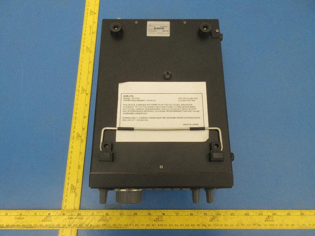
NVJAR5700D
Apr 21, 2020Digital Processing Communications Receiver
Equipment Class
CSR - Scanning Receiver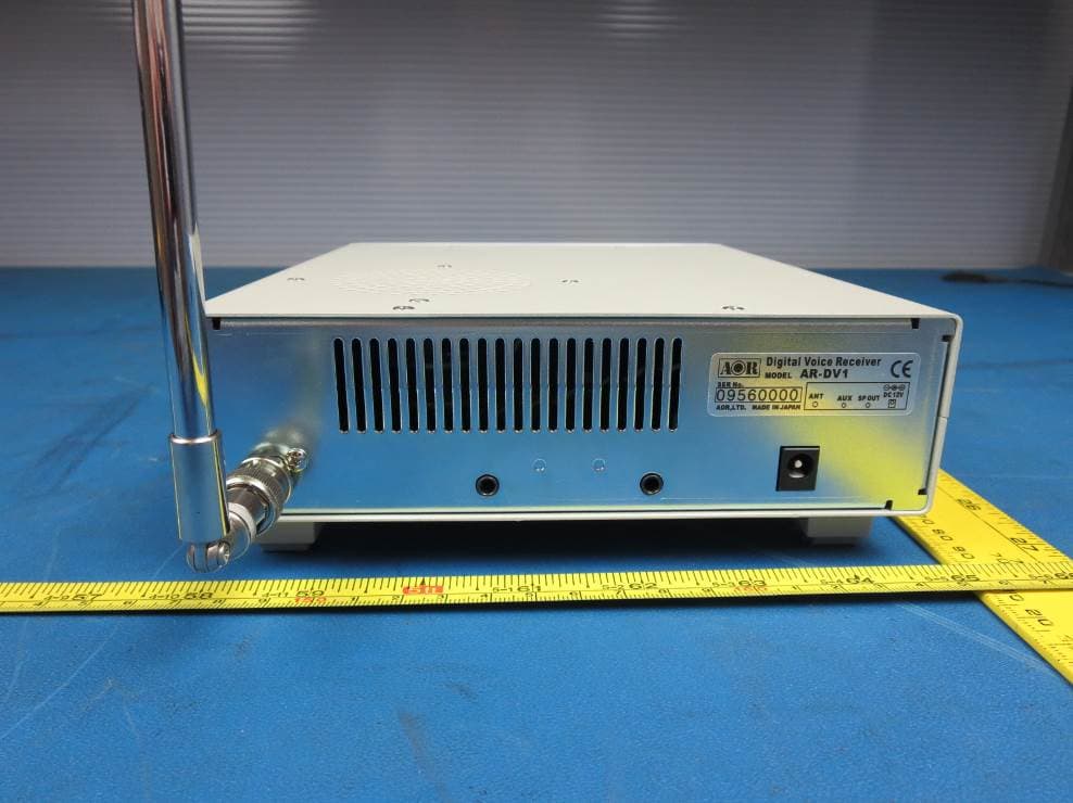
NVJARDV1
May 07, 2015Communications Receiver
Equipment Class
CSR - Scanning Receiver
NVJAR5001D
Aug 21, 2012Digital Processing Communication Receiver
Equipment Class
CSR - Scanning Receiver
NVJAR5000A
May 31, 2004AR5000A+3B Communications Receiver
Equipment Class
CSR - Scanning Receiver
NVJAR8600MK2B
Jul 14, 2002Transportable wide band all mode receiver
Equipment Class
CSR - Scanning Receiver