NVJAR8600MK2BTransportable wide band all mode receiver
AOR USA Inc.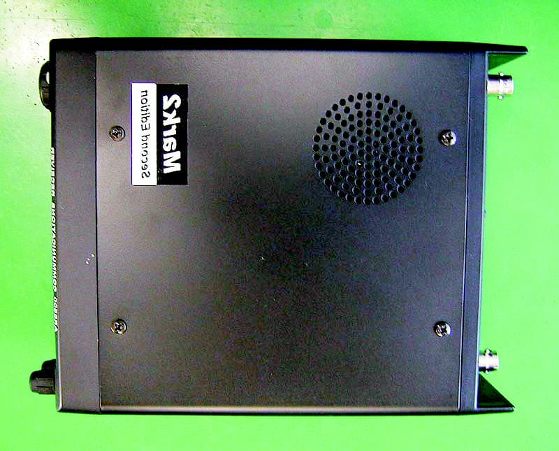
Click to zoom
Application Details
- Equipment Class
- CSR - Scanning Receiver
- Date of Grant
- Jul 14, 2002
- Application Purpose
- Original Equipment
- Date of Application
- Jul 14, 2002
- Equipment Note
- Transportable wide band all mode receiver
- Frequency Range
- 894.00000000 - 960.00000000
- Company
- AOR USA Inc.
- Country
- United States
Documents & Files
Document Text
Text extracted from the exhibit documents filed with the FCC. Open a document above to read the original.
Users Manual
Statement to be printed on the inside of the AR8600 User Manual cover page: WARNING: Modifications to this equipment are expressly forbidden by the FCC Rules. Any electrical or mechanical changes made to this device may cause harmful radio interference, and may void the user’s authority to operate the equipment.
Cover Letter(s)
American Telecommunications Certification Body Inc. 6731 Whittier Ave, McLean, VA 22101 July 1, 2002 RE: FCC ID: NVJAR8600MK2B Attention: Brian Haghtalab I have a few comments on this Application. 1 The internal photos are insufficient. The photos that were also uploaded are blurred. The required types of photos have not been provided. Please provide clear photos of both sides (top and bottom) of all circuit boards, photos of the controls, control LCD panel and inside of the chassis as required in CFR 47 Part 2. 2 During the testing of the device there are two ways to operate the receiver. The device can be placed in scanning mode and insured that it scans all appropriate frequencies (preferred) or the device can be set to low middle and high of each band. This means that if the device is set to low middle and high of each band, the number of bands tested in the report is insufficient. For example, there are at least three bands involved in this receiver. The frequencies below 824MHz to 30 MHz, the frequencies above 849MHz cellular bands up to 960 MHz and the frequencies below 30 MHz. Frequencies above 960MHz are not covered by Part 15. The manual shows a rotary switch with 12 selectable and separate bands. The technical description also shows 9 distinct receive modes (bands) Please explain why these bands were not used to determine the three frequency/band test criteria. Please provide test results showing testing in all appropriate bands. 3 CFR67 Part 15.121 (f) states, “Scanning receivers shall have a label permanently affixed to the product, and this label shall be readily visible to the purchaser at the time of purchase. The label shall read as follows: WARNING: MODIFICATION OF THIS DEVICE TO RECEIVE CELLULAR RADIOTELEPHONE SERVICE SIGNALS IS PROHIBITED UNDER FCC RULES AND FEDERAL LAW.” Please provide a drawing of this label that is to be on the device. 4 The manual does not contain the statement required in 15.21 (user’s information”. Please provide a manual with this statement. 5 The manual provided does not appear to be a complete manual. Please provide a complete manual as per FCC requirements. Dennis Ward mailto:[email protected] The items indicated above must be submitted before processing can continue on the above referenced application. Failure to provide the requested information may result in application termination. Correspondence should be considered part of the permanent submission and may be viewed from the Internet after a Grant of Equipment Authorization is issued. Please do not respond to this correspondence using the email reply button. In order for your response to be processed expeditiously, you must submit your documents through the AmericanTCB.com website. Also, please note that partial responses increase processing time and should not be submitted. Any questions about the content of this correspondence should be directed to the sender.
Cover Letter(s)
Mr. Dennis Ward Examining Engineer American T.C.B., Inc. 6731 Whittier Avenue McLean, VA 22101 July 15, 2002 RE:AOR USA NVJAR8600MK2B Dear Mr. Ward: The following list is the response to your technical information date July 1, 2002, regarding the above referenced application. 1. Please review attached corrected photos. 2. The radiated data represents the worse-case emissions produced in all bands while the AR8600 is placed in scanning mode. All bands between 100 kHz and 3 GHz were scanned and measured for radiated emissions. The highest levels in each band were reported. 3. Please find the label attachment file showing the warning statement to be placed on the AR8600. 4. Please find the manual warning attachment file showing the statement required by 15.21. 5. The user manual is currently not completed at this time Your expeditious response to this request is greatly appreciated, and Please do not hesitate to call me, should there be any questions or concerns. Sincerely, Brian Haghtalab Operations Manager
ID Label/Location Info
E E E X X X H H H I I I B B B I I I T T T 2 2 2 C C C l l l a a a s s s s s s “ “ “ B B B ” ” ” L L L a a a b b b e e e l l l i i i n n n g g g F F F o o o r r r m m m a a a t t t Label Location (Back View) AORMODEL AR8600 FCC ID:NVJAR8600MK2B This device complies with Part 15 of FCC Rules: Operation is subject to the following two conditions: (1) this device may not cause harmful interference, and (2) this device must accept any interference received, including interference that may cause undesired operation. AOR, LTD.Made in Japan FCCID LABEL Label to be placed on the back exterior of the AR8600: WARNING: Modification of this device to receive cellular radiotelephone service signals is prohibited under FCC Rules and Federal Law.
Test Report
NATIONAL CERTIFICATION LABORATORY 8370 Court Avenue, Suite B-1 Ellicot City, MD 21043 (410) 461-5548 For AOR, Ltd. 2-6-4 Misuji, Taito-ku Tokyo 111-0055 Japan Model: AR8600 Wide Range Receiver FCC ID:NVJAR8600MK2B June 14, 2002 FCC REPORT OF CERTIFICATION FCCID: NVJAR8600MK2B 1 TABLE OF CONTENTS 1.0 Introduction 1.1 Summary 2.0 Description of Equipment Under Test (EUT) 3.0Test Configuration 4.0 Conducted Emissions Scheme 5.0 Radiated Emissions Scheme TABLES Table 1.Support Equipment Table 2.Interface Cables Table 3. Measurement Equipment EXHIBITS Exhibit 1.EUT Photographs NCL PROJ.# AOR - 1423 FCCID: NVJAR8600MK2B 2 1.0 Introduction This report has been prepared on behalf of AOR, Ltd., to support the attached application for Certification of an Unintentional Radiator. The Equipment Under Test was the Model: AR8600 Wide Range Receiver. Radio-Noise Emissions tests were performed according to the ANSI C63.4- 1992, “Method of Measurement of RFI from Low-Voltage Electronic Equipment in the Range of 9 KHz- 40 GHz”. The measuring equipment conforms to ANSI C63.2 Specifications for electromagnetic Noise and Field Strength-Instrumentation. Test was performed at National Certification Laboratory in Ellicott City, MD. Site description and site attenuation data have been placed on file with the FCC’s sampling and Measurements Branch. FCC acceptance was granted on May 26, 1993. 1.1 Summary The AOR, Ltd. Model: AR8600 Wide Range Receiver, complies with the Part 15.121 Radio Limits for a Scanning Receiver. 2.0 Description of Equipment Under Test (EUT) The EUT Features: FEATURES FREQUENCY External Whip Antenna100 KHz – 3000 MHz Superheterodyne DesignCellular Band Block: 824 – 849 MHz Scanning Capabilities869 – 894 MHz 12.0 VDC Operation Software Controllable FCCID: NVJAR8600MK2B 3 3.0 Test Configuration The EUT was setup on the test table in a manner which follows the general guidelines of ANSI C63.4, Section 6 “General Operating Conditions and Configurations.” Tests were performed by exercising the receiver with an RF signal from the ambient airwaves. The receiver was tuned to a low, mid, and high frequency between 0.100 and 3000 MHz (tune range of the EUT) during testing. The EUT was connected to a Toshiba Tecra laptop computer via RS-232 cable during testing. This is described below: Whip Antenna Toshiba Laptop RS-232 cable EUT AC Adaptor 4.0 Conducted Emissions Scheme The EUT is placed on an 80 cm high 1 X 1.5 meter non-conductive table. Power to the CPU is provided through a Solar Corporation 50 Ω/50 μH line Impedance Stabilization Network bonded to a 2.2 X 2 meter horizontal ground plane, and a 2.2 X 2 meter vertical ground plane. The LISN has its AC input supplied from filtered AC power source. A separate LISN provides AC power to the peripheral equipment. I/O cables are moved about to obtain maximum emissions. The 50Ω output of the LISN is connected to the input of the spectrum analyzer and emissions in the frequency range of 450 kHz to 30 MHz are searched. The detector function is set to quasi- peak and the resolution bandwidth is set at 9 kHz, with all post-detector filtering no less than 10 times the resolution bandwidth for final measurements. All emissions within 20 dB of the limit are recorded in the data tables. 5.0 Radiated Emissions Scheme The EUT was initially scanned in the frequency range 30 to 5000 MHz indoors, at a distance of one (1) meter to determine its emissions profile. The EUT was then placed on an 80 cm high 1 X 1.5 meter non-conductive motorized turntable for radiated testing on the 3-Meter open area test FCCID: NVJAR8600MK2B 4 site. The emissions from the EUT are measured continuously at every azimuth by rotating the turntable. Waveguide horn and log periodic broadband antennas are mounted on an antenna mast to determine the height of maximum emissions. The height of the antenna is varied between one (1) and four (4) meters. Both the horizontal and vertical field components are measured. The output from the antenna is connected to the input of the spectrum analyzer. The detector function is set to Peak. All emissions within 20 dB of the limit are recorded in the data table. Measurements from 30-1000 MHz:The output from the antenna is connected to the input of the spectrum analyzer. The detector function is set to Quasi-Peak. The resolution bandwidth of the spectrum analyzer system is set at 120 kHz for the range 30-1000 MHz with all post- detector filtering no less than 10 times the resolution bandwidth. Measurements from 1-5 GHz:The output from the horn antenna is connected to the input of a 30 dB pre-Amp, which is in turn attached to the spectrum analyzer. The detector function is set to Peak. The resolution bandwidth of the spectrum analyzer system is set at 1 MHz for the range 1-4 GHz. To convert the spectrum analyzer reading into a quantified E-field level to allow comparison with the FCC limits. It is necessary to account for various calibration factors. These factors include cable loss (CL) and antenna factors (AF). The AF/CL in dB/m is algebraically added to the Spectrum Analyzer voltage in dBμV/m. This level is then compared with the FCC limit. EXAMPLE: Spectrum Analyzer Volt:VdBμV Composite factor:AF/CLdB/m Electric Field:EdBμV/m= VdBμV + AF/CLdB/m Linear Conversion:EμV/m= Antilog (EdBμV/m/20) FCCID: NVJAR8600MK2B 5 CLIENT: EUT:AR8600 RX CPU: TUNE: 0.100 - 3000 MHz MODE:Receiver QPQP E-FieldLimit MHzAnt.EUTdBuVdB/mdbuV/mdBuV/mdB 54.23VY19.0015.000.000.0034.0040.006.00 PASS 65.48VY15.0016.000.000.0031.0040.009.00PASS 78.91VY16.0012.000.000.0028.0040.0012.00 PASS 112.36VY19.0015.000.000.0034.0043.509.50 PASS 234.56HZ15.0021.000.000.0036.0046.0010.00 PASS 312.45HZ14.0014.000.000.0028.0046.0018.00 PASS Quasi-Peak Level POLARITYFREQUENCYSPEC AAF/C FCC RADIATED EMISSIONS DATA AOR, LTD. 3 METER TESTDATE: 06/11/02 MARGIN CONDITION AMP Gain dB Average Factor dB FCCID: NVJAR8600MK2B 6 1.1 AC Conducted Emissions Line 1 Plot: 1.2 AC Conducted Emissions Line 2 Plot: FCCID: N…
Text truncated - open the document above for the full version.
Contact Information
Applicant
Shigeru Takano
Technical Contact
National Certification LaboratoryBrian Haghtalab
[email protected](410) 461-5548
8370 Court Avenue · Ellicott City, Maryland · United States
Non-Technical Contact
National Certification LaboratoryBrian Haghtalab
[email protected](410) 461-5548
Test Firm
National Certification LaboratoryBrian Haghtalab
Technical Specifications
| # | Rule Parts | Frequency Range | Power Output |
|---|---|---|---|
| 3 | 15B | 894 MHz - 960 MHz | - |
Other Applications from AOR USA Inc.
NVJAR5700D
Apr 21, 2020Digital Processing Communications Receiver
Equipment Class
CSR - Scanning Receiver
NVJARDV1
May 07, 2015Communications Receiver
Equipment Class
CSR - Scanning Receiver
NVJAR5001D
Aug 21, 2012Digital Processing Communication Receiver
Equipment Class
CSR - Scanning Receiver
NVJAR5000A
May 31, 2004AR5000A+3B Communications Receiver
Equipment Class
CSR - Scanning Receiver
NVJAR8200MK3B
Oct 30, 2002Wide Band Scanning Receiver
Equipment Class
CSR - Scanning Receiver