O2O13192-EVBWPAN Transceiver
Digianswer A/S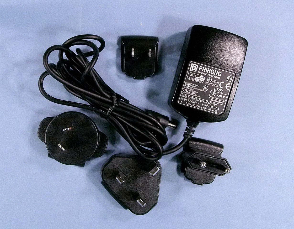
Click to zoom
Application Details
- Equipment Class
- DTS - Digital Transmission System
- Date of Grant
- Sep 21, 2004
- Application Purpose
- Original Equipment
- Date of Application
- Sep 21, 2004
- Equipment Note
- WPAN Transceiver
- Frequency Range
- 2405.00000000 - 2480.00000000
- Company
- Digianswer A/S
- Country
- Denmark
Documents & Files
Document Text
Text extracted from the exhibit documents filed with the FCC. Open a document above to read the original.
Users Manual
© Freescale Semiconductor, Inc., 2004. All rights reserved. Freescale Semiconductor Application Note AN2772 Rev. 0.0, 08/2004 1Introduction This document provides a detailed description of how to navigate through the Zigbee/802.15.4 application Evaluation Kit (EVK) package. The EVK package contains two evaluation printed circuit boards (PCBs). •DIG-528-2 EVK board •DIG-536-2 ARD board The boards are delivered with a pre-uploaded demonstration application. More demonstration applications can be uploaded with the delivered PC-tool which allows users to evaluate different application scenarios with the Freescale Zigbee/802.15.4 software solution. The delivered demonstration applications are PCB dependent, which means that a particular demonstration application designed for DIG-528-2 will not run on the DIG-536-2 SARD and vice versa. Demonstration Applications for the DIG-528-2 EVK include, but are not limited to: •PTC Demonstration (See AN2771/D for details.) Zigbee/802.15.4 Evaluation Kit Quick Start Guide Contents 1 Introduction . . . . . . . . . . . . . . . . . . . . . . . . . . 1 2 Safety Information . . . . . . . . . . . . . . . . . . . . . 2 3 References . . . . . . . . . . . . . . . . . . . . . . . . . . . 3 4 Primary Processor Overview . . . . . . . . . . . . 3 5 Printed Circuit Board Overview . . . . . . . . . . 4 6 Demonstration Applications . . . . . . . . . . . . . 6 Zigbee/802.15.4 Evaluation Kit, Rev. 0.0 2Freescale Semiconductor Safety Information •Switch Demonstration (See AN2773/D for details.) Demonstration Applications for the DIG-536-2 SARD include but are not limited to: •Accelerometer (See AN2762/D and AN 2774/D for details.) The Switch demonstration application is available with full source code which shows how to use some of the Zigbee/802.15.4 features and some of the main system features. This will show users how to interface to the 802.15.4 MAC/PHY and help users gain a better understanding about how to make their own applications. The source code is available for copying and modification. However, this requires that users build the source code, which requires that they have already installed the Metrowerks Codewarrior IDE for the HCS08 and have a full working license. Contact Metrowerks for more detailed information on how to get a license or to get a full working 30 day trial license. 2Safety Information Any modifications to this product may violate the rules of the Federal Communications Commission and make operation of the product unlawful. 47 C.F.R. Sec. 15.21 This equipment has been tested and found to comply with the limits for a Class B digital device, pursuant to part 15 of the FCC Rules. These limits are designed to provide reasonable protection against harmful interference in a residential installation. This equipment generates, uses and can radiate radio frequency energy and, if not installed and used in accordance with the instructions, may cause harmful interference to radio communications. However, there is no guarantee that interference will not occur in a particular installation. If this equipment does cause harmful interference to radio or television reception, which can be determined by turning the equipment off and on, the user is encouraged to try to correct the interference by one or more of the following measures: •Reorient or relocate the receiving antenna. •Increase the separation between the equipment and receiver. •Connect the equipment into an outlet on a circuit different from that to which the receiver is connected. •Consult the dealer or an experienced radio/TV technician for help. 47 C.F.R. Sec.15.105(b) This equipment complies with FCC radiation exposure limits set forth for an uncontrolled environment. The antenna(s) used for this equipment must be installed to provide a separation distance of at least 8 inches (20cm) from all persons. This device complies with Part 15 of the FCC Rules. Operation is subject to the following two conditions: 1. This device may not cause harmful interference. 2. This device must accept any interference received, including interference that may cause undesired operation. References Zigbee/802.15.4 Evaluation Kit, Rev. 0.0 Freescale Semiconductor3 3References The following documents were used as references to build this application note. 1. 802.15.4 MAC/PHY Software Reference Manual, 802154MPSRM/D 2. Zigbee.hlp (see Test Tool installation directory.\help) 3. PTC Demonstration Application Note, AN2771/D 4. Switch Demonstration Application Note, AN2773/D 5. Embedded Bootloader User's Guide, MC13192FLUG/D 6. HCSO8 Flash Library Application Note, AN2770/D 7. EVK Hardware Description Application Note, AN2731/D 8. HCS08 Micro controllers Data Sheet, MC9S0GB60/GT60 9. MC13192 Transceiver Data Sheet, MC13192DS/D 10. PCB Dependency Application Note, AN2769/D 4Primary Processor Overview The EVK package contains two PCBs. The DIG-528-2 EVK board and the DIG-536-2 ARD board. The two primary processors on the PCBs are the Freescale MC908HCS08 GT60 MCU and the Freescale MC 13192 RF chip. 4.1MCU MC908HCS08 GT60 Processor The MC908HCS08 GT60 is a member of Freescale's 8 bit, low-cost, high-performance HCS08 family. It has a 60 KB embedded flash and a 4 KB embedded RAM. A flash sector is 512 bytes. For more details refer to the EVK Hardware Description Application Note, AN2731/D and the HCS08 Micro controllers Data Sheet, MC9S0GB60/GT60. 4.2MC13192 Processor The Freescale MC13192 RF transceiver is a small radio that operates in the 2.4GHz ISM band. It has a Serial Peripheral Interface (SPI) interface for communication with the MCU. For more details about the MC13192 see the MC13192 Transceiver Data Sheet, MC13192DS/D. Zigbee/802.15.4 Evaluation Kit, Rev. 0.0 4Freescale Semiconductor Printed Circuit Board Overview 5Printed Circuit Board Overview As already stated, the EVK package contains two PCBs. The DIG-528-2 EVK board and the DIG-536-2 ARD board. This section highlights the hardware on both PCBs. 5.1DIG-528-2 Board …
Text truncated - open the document above for the full version.
Users Manual
MC13192 Ordering Information DeviceDevice MarkingPackage MC1319213192QFN-32 Package Information Plastic Package Case 1311-03 (QFN-32) (Scale 1:1) This document contains information on a product under development. Motorola reserves the right to change or discontinue this product without notice. © Motorola,Inc.,2004.All rights The MC13192 is a short range, low power, 2.4 GHz ISM band transceiver which contains a complete 802.15.4 physical layer (PHY) modem designed for the IEEE 802.15.4 wireless standard supporting star and mesh networking. When combined with an appropriate microcontroller (MCU), the MC13192 provides a cost effective solution for short-range data links and networks. Interface with the MCU is accomplished utilizing a four wire serial peripheral interface (SPI) connection which allows for the use of a variety of processors. The software and processor can be scaled to fit applications ranging from simple point-to-point systems, through complete ZigBee™ networking. For more detailed information on MC13192 operation, refer to the MC13192 Reference Manual, part number MC13192RM/D. Applications include, but are not limited to, the following: •Remote control and wire replacement in industrial systems such as wireless sensor networks •Factory automation and motor control •Heating and cooling •Inventory management and RF ID tagging Potential consumer applications include: •Home automation and control •Human interface devices •Remote entertainment control Product Preview MC13192/D Rev. 2.4, 06/2004 2.4 GHz, Low Power Transceiver for 802.15.4 Contents 1 Features . . . . . . . . . . . . . 2 2 Block Diagrams . . . . . . . 3 3 Data Transfer Modes . . 3 4Electrical Characteristics . . . . . . . 5 5Functional Description . . . . . . . . . . 8 6 Contact Connections . . . . . . . . 11 7 Applications Information . . . . . . . . . . 15 8 Packaging Information . . . . . . . . . . 18 F r e e s c a l e S e m i c o n d u c t o r , I Freescale Semiconductor, Inc. n c . . . 2MC13192 Product PreviewMOTOROLA Features •Wireless toys The transceiver includes a low noise amplifier, 1.0 mW PA, VCO, full spread-spectrum encoding and decoding. The device supports 250 kbps O-QPSK data in 5.0 MHz channels, per the IEEE 802.15.4 specification. A Serial Peripheral Interface (SPI) is used for RX and TX data transfer and control. 1 Features •Recommended power supply range: 2.0 to 3.4 V •16 Channels •0 dBm (Typical), up to 3.6 dBm maximum output power •Buffered Transmit and Receive Data Packets for Simplified Use with Low Cost Microcontrollers •Supports 250 kbps O-QPSK Data in 5.0 MHz Channels and Full Spread-Spectrum Encode and Decode (Compatible with IEEE Standard 802.15.4) •Three Power Down Modes for Power Conservation: — < 1 μ A Off Current — 3.0 μ A Typical Hibernate Current — 40 μ A Typical Doze Current •RX sensitivity of -92 dBm (Typical) at 1.0% Packet Error Rate •Four internal timer comparators are available to reduce MCU resource requirements •Clock output is available for use by MCU •Seven General Purpose Input/Output ports (GPIO) are available •Operating Temperature Range: -40°C to 85°C •Small form factor QFN-32 Package — Meets Moisture Sensitivity Level (MSL) 3 — 260°C Peak Reflow temperature — Meets lead-free requirements F r e e s c a l e S e m i c o n d u c t o r , I Freescale Semiconductor, Inc. n c . . . Block Diagrams MOTOROLAMC13192 Product Preview3 2 Block Diagrams Figure 1 shows a simplified block diagram of the MC13192. The MC13192 is an IEEE 802.15.4 transceiver that provides most of the functions required in the Physical Layer (PHY) specification. Figure 2 shows the basic system block diagram for the MC13192 in an application. Interface with the IC is accomplished through a 4-wire Serial Peripheral Interface (SPI). The Medium Access Control (MAC), drivers, and Network and Application software as required reside on the host processor. The host can be anything from a simple 8-bit device up to a sophisticated 32-bit processor depending on application requirements. 3 Data Transfer Modes The MC13192 has two data transfer modes: 1. Packet Mode — Data is buffered in on-chip RAM 2. Streaming Mode — Data is processed word by word When using the Motorola 802.15.4 MAC, only the streaming mode can be used. For proprietary applications, packet mode is used to conserve MCU resources. 3.1 Packet Structure Figure 3 shows the packet structure of the MC13192. Payloads of up to 125 bytes are supported. The MC13192 adds a four byte preamble, a one byte start of frame delimiter (SFD), and a one byte frame length indicator before the data. A Frame Check Sequence (FCS) is calculated and appended to the end of the data. 3.2 Receive Path Description In the receive signal path, the RF input is converted to low IF In-phase and Quadrature (I & Q) signals through two down conversion stages. A Clear Channel Assessment (CCA) can be performed based on the baseband energy integrated over a specific time interval. The digital back end performs Differential Chip Detection (DCD), the correlator “de spreads” the Direct Sequence Spread Spectrum (DSSS) Offset QPSK (O-QPSK) signal, determines the symbols and packets, and detects the data. The preamble, SFD, and frame length are parsed and used. A two-byte FCS is calculated and compared to the FCS value appended to the transmitted data, generating a Cyclical Redundancy Check (CRC) result. Link Quality is measured over a 64 μ s period after the packet preamble and stored in ROM. If the MC13192 is in packet mode, the data is processed as an entire packet. The MCU is notified that an entire packet has been received via an interrupt. If the MC13192 is in streaming mode, the MCU is notified by an interrupt on a word by word basis. 3.3 Transmit Path Description The transmit path is the exact reverse of the receive path. The data stored in RAM is retrieved or clocked in via the SPI, formed into packets per the 802.15.4 PHY, spread, and then up converted to the transmit frequency. If the…
Text truncated - open the document above for the full version.
External Photos
FCC ID: O2O13192-EVB Project no.: 04/750 Page 5 of 6 AC adapter with different plugs AC adapter with different plugs with numbers Nemko Comlab AS, N-2027 Kjeller FCC ID: O2O13192-EVB Project no.: 04/750 Page 6 of 6 Nemko Comlab AS, N-2027 Kjeller Supplied accessories for Testing
Internal Photos
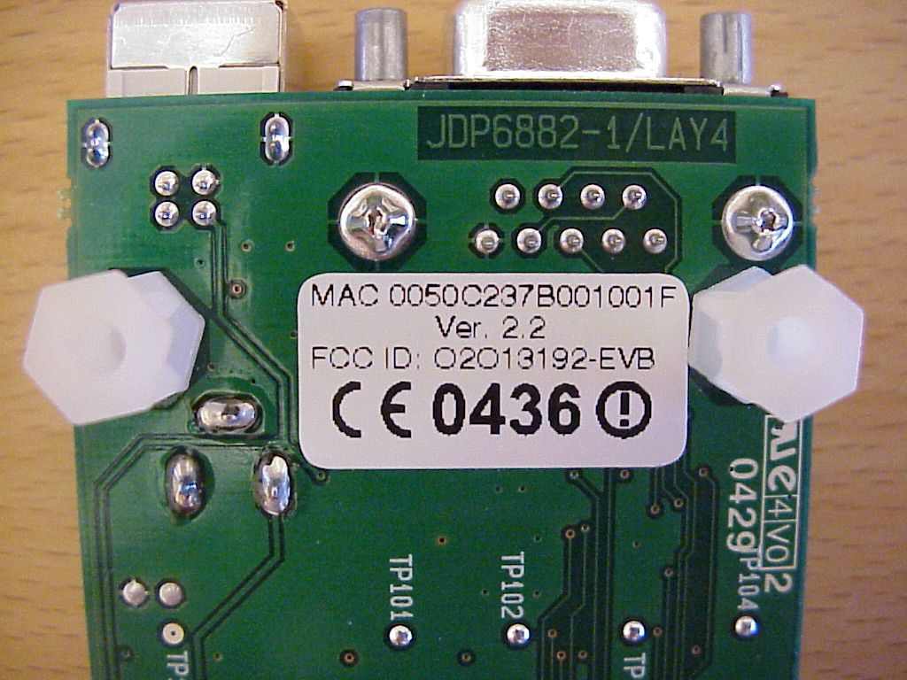
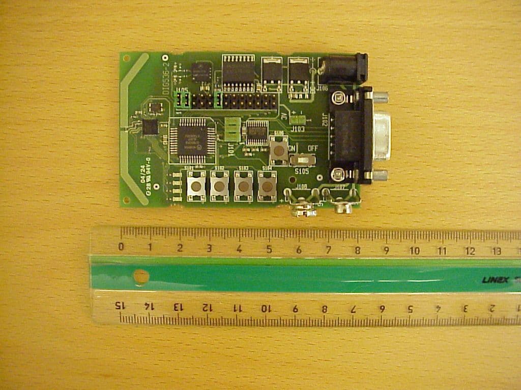
FCC ID: O2O13192-EVB Project no.: 04/750 Page 3 of 6 13192-EVB, top view 13192-EVB, rear view Nemko Comlab AS, N-2027 Kjeller FCC ID: O2O13192-EVB Project no.: 04/750 Page 4 of 6 13192-EVB, view of RS 232 port and USB port 13192-EVB, view of power connector Nemko Comlab AS, N-2027 Kjeller
Operational Description
Project: Technical Specification Appendix Subject: FCC Approval (TCB) Date: 12/08/2004 3:28 PM Author: JJONAS1 Rev: 1.0 Path: Technical_Specification_Appendix_DIG528_02.03_Revision_1.0.doc Page: 1 of 1 Digianswer A/S Confidential and Proprietary This document contains Digianswer A/S confidential and proprietary information, which you are not entitled to use, reproduce or disclose to any third party without the prior written consent of Digianswer A/S. Digianswer 2001 Version 01 blt Technical Specification Appendix Product: MC13192 Evaluation Board. FCC ID: O2O13192-EVB Frequency band = 2400-2483.5 MHz Spreading Parameters: Chip rate = 2.0 Mchip/s Modulation = 0-QPSK Data Parameters: Bit rate = 250 kbit/s Symbol rate = 62.5 ksymbols/s Number of channels = 16 Channel 11 = 2405 MHz Channel 12 = 2410 MHz Channel 13 = 2415 MHz Channel 14 = 2420 MHz Channel 15 = 2425 MHz Channel 16 = 2430 MHz Channel 17 = 2435 MHz Channel 18 = 2440 MHz Channel 19 = 2445 MHz Channel 20 = 2450 MHz Channel 21 = 2455 MHz Channel 22 = 2460 MHz Channel 23 = 2465 MHz Channel 24 = 2470 MHz Channel 25 = 2475 MHz Channel 26 = 2480 MHz Channel bandwidth = 5 MHz Antenna gain, maximum = 3.51 dBi Package length = 176μS to 4256μS
Test Report
Pages : 36 Total no. of sheets : 36 Test report : 04/750/2 Item tested : 13192-EVB Type of equipment : WPAN transceiver FCC ID : O2O13192-EVB Client : Digianswer A/S Tested according to : FCC part 15.247 DTS Transmitter 2405 - 2480 MHz Date of issue : 20 September 2004 Authorized by : The results detailed in this test report applies only to the particular sample(s) tested and with configuration(s) as implemented during testing. This test report shall not be reproduced, except in full, without the written approval of Nemko Comlab AS. Any use which a third party makes of this report, or any reliance on or decisions to be made based on it, are the responsibility of such third parties. Nemko Comlab AS accepts no responsibility for damages, if any, suffered by any third party as a result of decisions made or actions based on this report. FCC 15.247 Test Report FCC ID: O2O13192-EVB Project no.: 04/750/2 Page 2 of 36 CONTENTS 1 GENERAL INFORMATION.......................................................................................... 3 1.1 Test house Info............................................................................................................3 1.2 Client Information.........................................................................................................3 1.3 Manufacturer................................................................................................................3 2 Test Information...........................................................................................................4 2.1 Tested Item..................................................................................................................4 2.2 Test Environment.........................................................................................................4 2.3 Test Period...................................................................................................................4 3 TEST REPORT SUMMARY........................................................................................5 3.1 General........................................................................................................................5 3.2 Test Summary..............................................................................................................6 3.3 Description of modification for Modification Filing.......................................................6 3.4 Comments....................................................................................................................6 3.5 Family List Rational......................................................................................................6 4 TEST RESULTS..........................................................................................................7 4.1 Power line Conducted Emissions................................................................................7 4.2 Minimum 6 dB Bandwidth..........................................................................................10 4.3 Peak Power Output....................................................................................................13 4.4 Spurious Emissions (conducted scan up to 25 GHz)................................................16 4.5 Upper Band Edge Radiated Emissions.....................................................................19 4.6 Out-of-band emissions (Radiated).............................................................................20 4.7 Power Spectral Density (PSD)...................................................................................31 LIST OF TEST EQUIPMENT.........................................................................................................34 5 BLOCK DIAGRAM.....................................................................................................35 5.1 System set up............................................................................................................35 5.2 Power line Conducted Emission................................................................................35 5.3 Test Site Radiated Emission and peak power output................................................36 Nemko Comlab AS, N-2027 Kjeller FCC 15.247 Test Report FCC ID: O2O13192-EVB Project no.: 04/750/2 Page 3 of 36 1 GENERAL INFORMATION 1.1 Test house Info Name : Nemko Comlab AS Address : Gåsevikveien 8, Box 96 N-2027 Kjeller, NORWAY Telephone : +47 64 84 57 00 Fax : +47 64 84 57 05 E-mail: mailto:[email protected] Managing Director: Kjell G. Haga FCC test firm registration number : 994405 Industry Canada OATS registration number : 4443 1.2 Client Information Name : Digianswer A/S Address : Skalhuse 5, 9240 Nibe, Denmark Telephone : +45 967 10 000 Fax : +45 983 50 052 Contact: Name : Johnny Jonassen Telephone : +45 967 12 153 E-mail : [email protected] 1.3 Manufacturer Name : Digianswer A/S Address : Skalhuse 5, 9240 Nibe, Denmark Telephone : +45 967 10 000 Fax : +45 983 50 052 Nemko Comlab AS, N-2027 Kjeller FCC 15.247 Test Report FCC ID: O2O13192-EVB Project no.: 04/750/2 Page 4 of 36 2 Test Information 2.1 Tested Item Name : 13192-EVB FCC ID : O2O13192-EVB Model/version : 13192-EVB Serial number : Marked on PCB “13192-EVB” Hardware identity and/or version: 80000528000_R0203 Software identity and/or version : PTC Version 1.00 Frequency Range : 2405 - 2480 MHz Tunable Bands : 1 Number of Channels : 16 1 Modulation : 0-QPSK Emissions Designator : G1D User Frequency Adjustment : None, Software controlled. Rated Output Power : 10 mW 1) 16 channels in use. Theory of Operation The MC13192-EVB is a “WPAN” low data rate wireless device according to IEEE 802.15.4 (Zigbee), with 5 MHz channel bandwidth. 2.2 Test Environment 2.2.1 Normal test condition Temperature: 20 - 25 °C Relative humidity: 25 - 50 % Normal test voltage: 115 V AC The values are the limit registered during the test period. 2.3 Test Period Item received date: 2004-08-23 Test period : from 200…
Text truncated - open the document above for the full version.
Contact Information
Applicant
Jorgen Holst(Functional Manager, Platform & IT)
Test Firm
Nemko ASFrode Sveinsen
Technical Specifications
| # | Rule Parts | Frequency Range | Power Output |
|---|---|---|---|
| 1 | 15C | 2.40 GHz - 2.48 GHz | 13.30 mW |
Other Applications from Digianswer A/S
O2O13192-SARD
Aug 24, 2004IEEE 802.15.4 Transceiver
Equipment Class
DTS - Digital Transmission System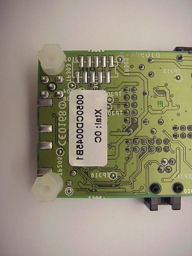
O2OBTDVK110
Jan 22, 2003Bluetooth Developer Kit
Equipment Class
DSS - Part 15 Spread Spectrum Transmitter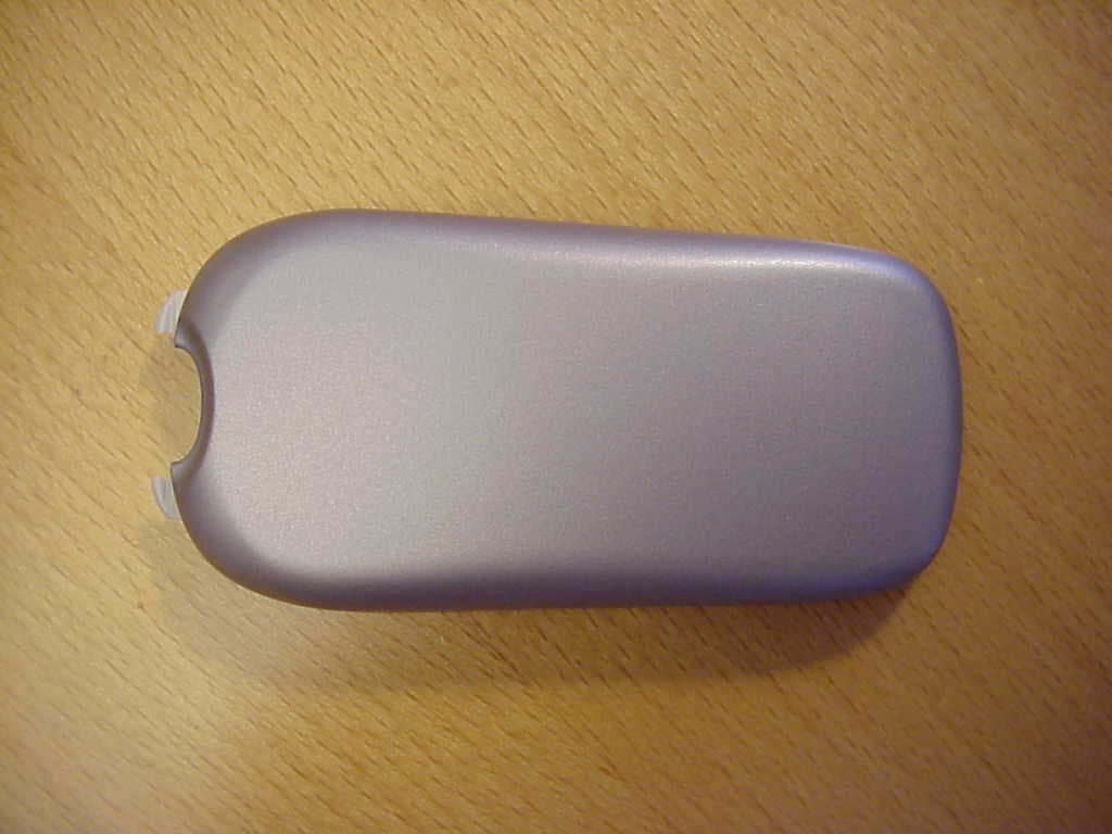
O2OBTP2M100
Jul 16, 2002Motorola Bluetooth Phone Module
Equipment Class
DSS - Part 15 Spread Spectrum Transmitter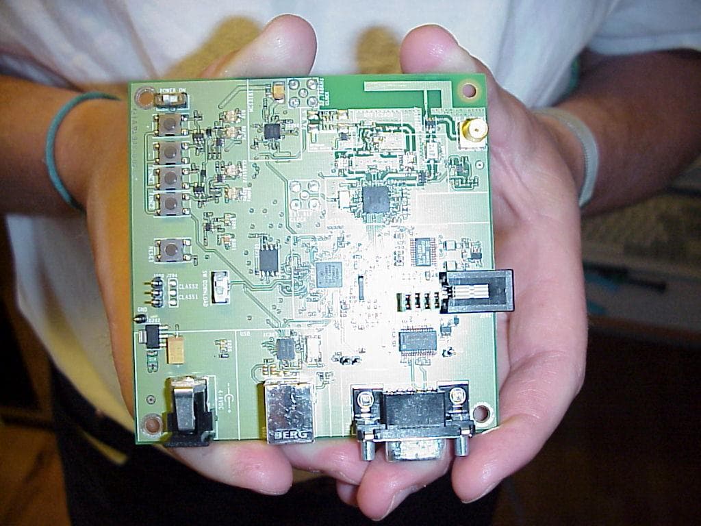
O2OBTDVK100
Jun 27, 2002Bluetooth Developer Kit
Equipment Class
JBP - Part 15 Class B Computing Device Peripheral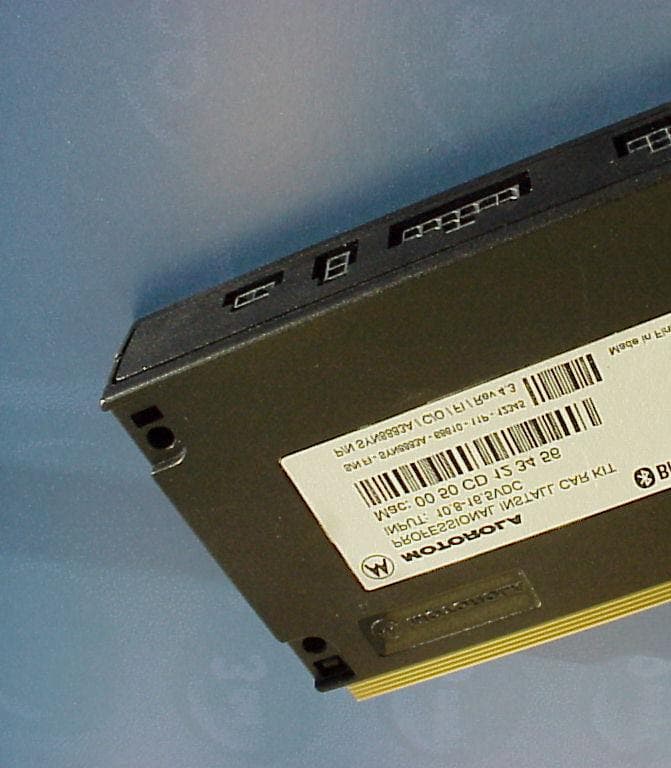
O2OBTHCK100
Apr 23, 2002Bluetooth Hands Free Car Kit
Equipment Class
DSS - Part 15 Spread Spectrum Transmitter