O2O13192-SARDIEEE 802.15.4 Transceiver
Digianswer A/S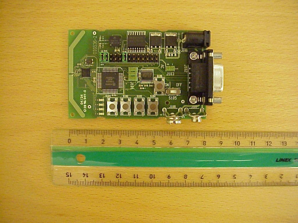
Click to zoom
Application Details
- Equipment Class
- DTS - Digital Transmission System
- Date of Grant
- Aug 24, 2004
- Application Purpose
- Original Equipment
- Date of Application
- Aug 24, 2004
- Equipment Note
- IEEE 802.15.4 Transceiver
- Frequency Range
- 2405.00000000 - 2480.00000000
- Company
- Digianswer A/S
- Country
- Denmark
Documents & Files
Document Text
Text extracted from the exhibit documents filed with the FCC. Open a document above to read the original.
Users Manual
MC13192SARDUG/D Rev. 1.1, 08/2004 Sensor Applications Reference Design (SARD) User’s Guide HOW TO REACH US: USA/EUROPE/LOCATIONS NOT LISTED: Motorola Literature Distribution; P.O. Box 5405, Denver, Colorado 80217 1-303-675-2140 or 1-800-441-2447 JAPAN: Motorola Japan Ltd.; SPS, Technical Information Center, 3-20-1, Minami-Azabu Minato-ku, Tokyo 106-8573 Japan 81-3-3440-3569 ASIA/PACIFIC: Motorola Semiconductors H.K. Ltd.; Silicon Harbour Centre, 2 Dai King Street, Tai Po Industrial Estate, Tai Po, N.T., Hong Kong 852-26668334 TECHNICAL INFORMATION CENTER: 1-800-521-6274 HOME PAGE: http://www.motorola.com/semiconductors Information in this document is provided solely to enable system and software implementers to use Motorola products. There are no express or implied copyright licenses granted hereunder to design or fabricate any integrated circuits or integrated circuits based on the information in this document. Motorola reserves the right to make changes without further notice to any products herein. Motorola makes no warranty, representation or guarantee regarding the suitability of its products for any particular purpose, nor does Motorola assume any liability arising out of the application or use of any product or circuit, and specifically disclaims any and all liability, including without limitation consequential or incidental damages. “Typical” parameters which may be provided in Motorola data sheets and/or specifications can and do vary in different applications and actual performance may vary over time. All operating parameters, including “Typicals” must be validated for each customer application by customer’s technical experts. Motorola does not convey any license under its patent rights nor the rights of others. Motorola products are not designed, intended, or authorized for use as components in systems intended for surgical implant into the body, or other applications intended to support or sustain life, or for any other application in which the failure of the Motorola product could create a situation where personal injury or death may occur. Should Buyer purchase or use Motorola products for any such unintended or unauthorized application, Buyer shall indemnify and hold Motorola and its officers, employees, subsidiaries, affiliates, and distributors harmless against all claims, costs, damages, and expenses, and reasonable attorney fees arising out of, directly or indirectly, any claim of personal injury or death associated with such unintended or unauthorized use, even if such claim alleges that Motorola was negligent regarding the design or manufacture of the part. Motorola and the Stylized M Logo are registered in the U.S. Patent and Trademark Office. All other product or service names are the property of their respective owners. Motorola, Inc. is an Equal Opportunity/Affirmative Action Employer. © Motorola, Inc. 2004 MOTOROLAContentsiii Contents Chapter 1 Introduction and Configuration 1.1Safety Information . . . . . . . . . . . . . . . . . . . . . . . . . . . . . . . . . . . . . . . . . . . . . . . . . . . . . 1-1 1.2MC13192 Sensor Applications Reference Design (SARD) Components . . . . . . . . . . . 1-2 1.3Hardware Description . . . . . . . . . . . . . . . . . . . . . . . . . . . . . . . . . . . . . . . . . . . . . . . . . . . 1-3 1.3.1MC13192 SARD Circuit Description . . . . . . . . . . . . . . . . . . . . . . . . . . . . . . . . . . . . 1-3 1.3.2RS232 Connector J102 . . . . . . . . . . . . . . . . . . . . . . . . . . . . . . . . . . . . . . . . . . . . . . . 1-5 1.3.3Power Capability. . . . . . . . . . . . . . . . . . . . . . . . . . . . . . . . . . . . . . . . . . . . . . . . . . . . 1-6 1.3.4LEDs and Switches . . . . . . . . . . . . . . . . . . . . . . . . . . . . . . . . . . . . . . . . . . . . . . . . . . 1-6 1.3.5Board Reset Function . . . . . . . . . . . . . . . . . . . . . . . . . . . . . . . . . . . . . . . . . . . . . . . . 1-6 1.3.6MCU General Purpose Input/Output (GPIO) . . . . . . . . . . . . . . . . . . . . . . . . . . . . . . 1-6 1.3.7BDM Port . . . . . . . . . . . . . . . . . . . . . . . . . . . . . . . . . . . . . . . . . . . . . . . . . . . . . . . . . 1-6 1.4Applications and Programming Information . . . . . . . . . . . . . . . . . . . . . . . . . . . . . . . . . 1-7 1.4.1Accelerometer Application Demo . . . . . . . . . . . . . . . . . . . . . . . . . . . . . . . . . . . . . . 1-7 1.4.2Programming the SARD (User Defined Software) . . . . . . . . . . . . . . . . . . . . . . . . . 1-7 Appendix A SARD Board Layout and Bill of Materials ivSensor Applications Reference Design (SARD) User’s GuideMOTOROLA MOTOROLAList of Figuresv List of Figures Figure 1-1Point to Point MC13192 SARD Block Diagram . . . . . . . . . . . . . . . . . . . . . . . . 1-3 Figure 1-2MC13192 SARD Schematic . . . . . . . . . . . . . . . . . . . . . . . . . . . . . . . . . . . . . . . . 1-4 Figure 1-3DCE-DB9 Female Connector (Looking into the SARD Connector) . . . . . . . . . 1-5 Figure 1-4SARD Component Layout . . . . . . . . . . . . . . . . . . . . . . . . . . . . . . . . . . . . . . . . . 1-5 Figure A-1PCB Layout (Top View) . . . . . . . . . . . . . . . . . . . . . . . . . . . . . . . . . . . . . . . . . . . A-1 Figure A-2PCB Layout (Bottom View) . . . . . . . . . . . . . . . . . . . . . . . . . . . . . . . . . . . . . . . . A-2 Figure A-3Printed Circuit Board Antenna Dimensions . . . . . . . . . . . . . . . . . . . . . . . . . . . . A-3 viSensor Applications Reference Design (SARD) User’s GuideMOTOROLA MOTOROLAList of Tablesvii List of Tables Table 1-1LED and Switch Port Connection. . . . . . . . . . . . . . . . . . . . . . . . . . . . . . . . . . . . 1-6 Table A-1Bill of Materials (BOM) . . . . . . . . . . . . . . . . . . . . . . . . . . . . . . . . . . . . . . . . . . . A-4 viiiSensor Applications Reference Design (SARD) User’s GuideMOTOROLA MOTOROLAAbout This Bookix About This Book This guide provides detailed information about the MC13192 Sensor Applications Reference Design (SA…
Text truncated - open the document above for the full version.
RF Exposure Info
Prediction of MPE limit at a given distance Equation from page 18 of OET Bulletin 65, Edition 97-01where: S = power density P = power input to the antennaG = power gain of the antenna in the direction of interest relative to an isotropic radiatorR = distance to the center of radiation of the antenna Maximum peak output power at antenna input terminal: 12.10 (dBm) Maximum peak output power at antenna input terminal: 16.21810097 (mW) Antenna gain(typical): 0.00 (dBi) Maximum antenna gain: 1 (numeric) Prediction distance: 20 (cm) Prediction frequency: 2400 (MHz) MPE limit for uncontrolled exposure at prediction frequency: 1.00 (mW/cm^2) Power density at prediction frequency: 0.003226 (mW/cm^2) Maximum allowable antenna gain: 24.91 (dBi) Margin of Compliance: 24.91 (dB) 2 4 R PG S π =
Test Report
Pages : 32 Total no. of sheets : 32 Test report : 04/720/3 Item tested : 13192-SARD Type of equipment : Zigbee transceiver FCC ID : O2O13192-SARD Client : Digianswer A/S Tested according to : FCC part 15.247 DTS Transmitter 2405 - 2480 MHz Date of issue : 16 July 2004 Authorized by : The results detailed in this test report applies only to the particular sample(s) tested and with configuration(s) as implemented during testing. This test report shall not be reproduced, except in full, without the written approval of Nemko Comlab AS. Any use which a third party makes of this report, or any reliance on or decisions to be made based on it, are the responsibility of such third parties. Nemko Comlab AS accepts no responsibility for damages, if any, suffered by any third party as a result of decisions made or actions based on this report. Test Report FCC ID: O2O13192-SARD Project no.: 04/720/3 Page 2 of 32 CONTENTS 1 GENERAL INFORMATION.......................................................................................... 3 1.1 Test house Info............................................................................................................3 1.2 Client Information.........................................................................................................3 1.3 Manufacturer................................................................................................................3 2 Test Information...........................................................................................................4 2.1 Tested Item..................................................................................................................4 2.2 Test Environment.........................................................................................................4 2.3 Test Period...................................................................................................................4 3 TEST REPORT SUMMARY........................................................................................5 3.1 General........................................................................................................................5 3.2 Test Summary..............................................................................................................6 3.3 Description of modification for Modification Filing.......................................................6 3.4 Comments....................................................................................................................6 3.5 Family List Rational......................................................................................................6 4 TEST RESULTS..........................................................................................................7 4.1 Power line Conducted Emissions................................................................................7 4.2 Bandwidth..................................................................................................................12 4.3 Peak Power Output....................................................................................................15 4.4 Out-of-band emissions (Radiated).............................................................................18 4.5 Power Spectral Density (PSD)...................................................................................29 LIST OF TEST EQUIPMENT.........................................................................................................30 5 BLOCK DIAGRAM.....................................................................................................31 5.1 System set up............................................................................................................31 5.2 Power line Conducted Emission................................................................................31 5.3 Test Site Radiated Emission and peak power output................................................32 Nemko Comlab AS, N-2027 Kjeller Test Report FCC ID: O2O13192-SARD Project no.: 04/720/3 Page 3 of 32 1 GENERAL INFORMATION 1.1 Test house Info Name : Nemko Comlab AS Address : Gåsevikveien 8, Box 96 N-2027 Kjeller, NORWAY Telephone : +47 64 84 57 00 Fax : +47 64 84 57 05 E-mail: mailto:[email protected] Managing Director: Kjell G. Haga FCC test firm registration number : 994405 Industry Canada OATS registration number : 4443 1.2 Client Information Name : Digianswer A/S Address : Skalhuse 5, 9240 Nibe, Denmark Telephone : +45 967 10 000 Fax : +45 983 50 052 Contact: Name : Johnny Jonassen Telephone : +45 967 12 153 E-mail : [email protected] 1.3 Manufacturer Name : Digianswer A/S Address : Skalhuse 5, 9240 Nibe, Denmark Telephone : +45 967 10 000 Fax : +45 983 50 052 Nemko Comlab AS, N-2027 Kjeller Test Report FCC ID: O2O13192-SARD Project no.: 04/720/3 Page 4 of 32 2 Test Information 2.1 Tested Item Name : 13192-SARD FCC ID : O2O13192-SARD Model/version : DIG536-2 Serial number : Marked on PCB “13192-SARD” Hardware identity and/or version: 80000536000_R0201 Software identity and/or version : PTC Demo ver.0.99 Frequency Range : 2405 - 2480 MHz Tunable Bands : 1 Number of Channels : 16 1 Modulation : 0-QPSK Emissions Designator : G1D User Frequency Adjustment : None, Software controlled. Rated Output Power : 10 mW 1) 16 channels in use. Theory of Operation The 13192-SARD is a “Zigbee” low data rate wireless device according to IEEE 802.15.4, with 5MHz channel bandwidth. 2.2 Test Environment 2.2.1 Normal test condition Temperature: 20 - 23 °C Relative humidity: 29 - 50 % Normal test voltage: 9.0 V DC The values are the limit registered during the test period. 2.3 Test Period Item received date: 2004-07-02 Test period : from 2004-07-06 to 2004-07-07 Nemko Comlab AS, N-2027 Kjeller Test Report FCC ID: O2O13192-SARD Project no.: 04/720/3 Page 5 of 32 3 TEST REPORT SUMMARY 3.1 General Manufacturer: Digianswer A/S Model No.: 13192-SARD Serial No.: Marked on PCB “1319…
Text truncated - open the document above for the full version.
Test Report
Nemko Comlab AS 24.08.2004 Project No.: 04/720/3 Page 1 (2) Upper Band Edge Radiated Emissions This document calculates the spurious radiations at the upper band edge (at 2483.5 MHz) when the equipment is transmitting on channel 26. All measurements were performed at 3 metres. The calculations are done according to the “Marker-Delta Method”. Nemko Comlab AS 24.08.2004 Project No.: 04/720/3 Page 2 (2) Peak field strength at 2.480GHz, ch 26 Marker delta , ch 26, Upper Band Edge Peak Field Strength: 101.96 dBμV/m Marker Delta 100kHz RBW: 33.1dB Therefore: Peak Field Strength 102.0 – 33.1 = 68.9 dBμV/m Average Field Strength: 68.9 dBμV/m – 20.0 dB = 48.9 dBμV/m
Test Setup Photos
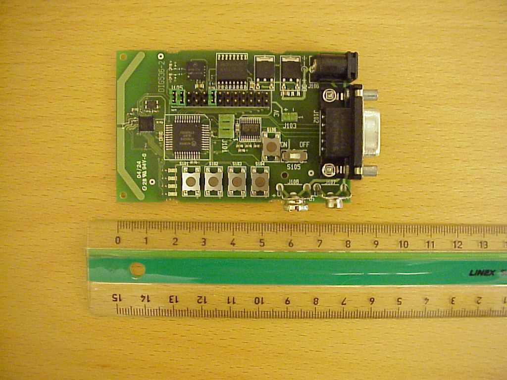
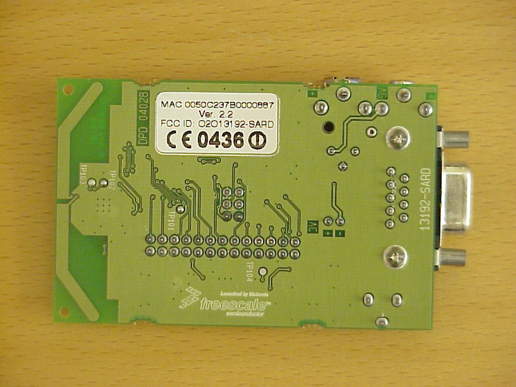
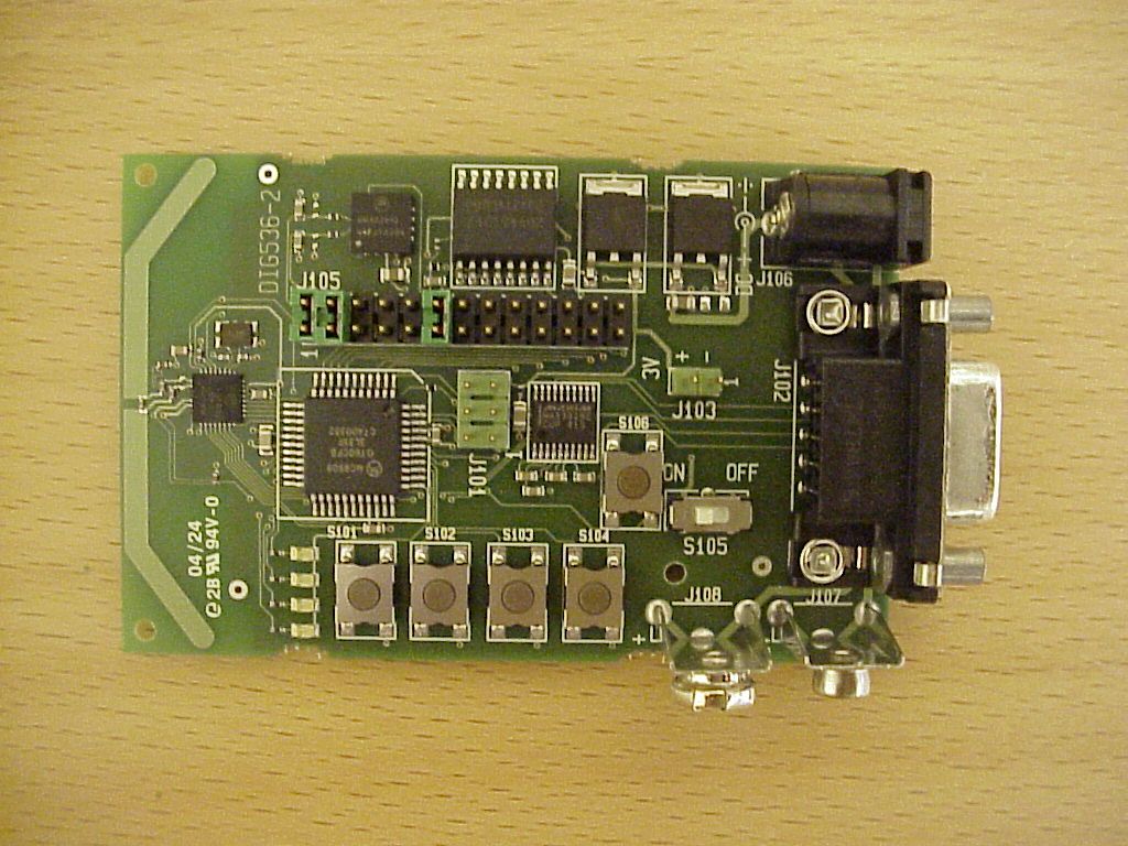
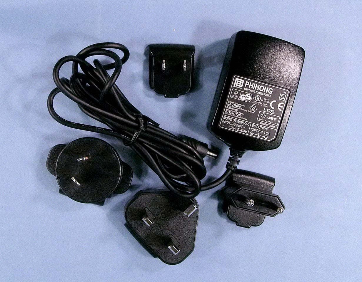
FCC ID: O2O13192-SARD Project no.: 04/720 Page 1 of 5 PHOTOS OF TEST SET-UP AND THE TESTED EQUIPMENT Radiated emissions 30 - 200 MHz Radiated emissions 200 - 1000 MHz Nemko Comlab AS, N-2027 Kjeller FCC ID: O2O13192-SARD Project no.: 04/720 Page 2 of 5 Radiated emission above 1 GHz Test setup, Conducted emissions Nemko Comlab AS, N-2027 Kjeller FCC ID: O2O13192-SARD Project no.: 04/720 Page 3 of 5 13192-SARD with integrated antenna, top view 13192-SARD with integrated antenna, rear view Nemko Comlab AS, N-2027 Kjeller FCC ID: O2O13192-SARD Project no.: 04/720 Page 4 of 5 13192-SARD with integrated antenna, view of RS 232 port , AC adapter and DC battery ports AC adapter with different plugs Nemko Comlab AS, N-2027 Kjeller FCC ID: O2O13192-SARD Project no.: 04/720 Page 5 of 5 Nemko Comlab AS, N-2027 Kjeller AC adapter with different plugs with numbers Supplied accessories for Testing
Contact Information
Applicant
Jorgen Holst(Functional Manager, Platform & IT)
Technical Contact
Non-Technical Contact
Nemko Comlab ASFrode Sveinsen
[email protected]+47 6484 5700
Test Firm
Nemko ASFrode Sveinsen
Technical Specifications
| # | Rule Parts | Frequency Range | Power Output |
|---|---|---|---|
| 1 | 15C | 2.40 GHz - 2.48 GHz | 16.30 mW |
Other Applications from Digianswer A/S
O2O13192-EVB
Sep 21, 2004WPAN Transceiver
Equipment Class
DTS - Digital Transmission System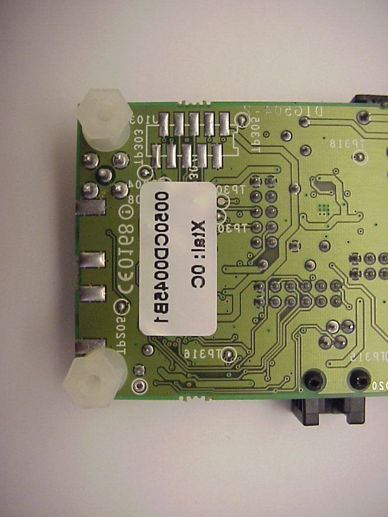
O2OBTDVK110
Jan 22, 2003Bluetooth Developer Kit
Equipment Class
DSS - Part 15 Spread Spectrum Transmitter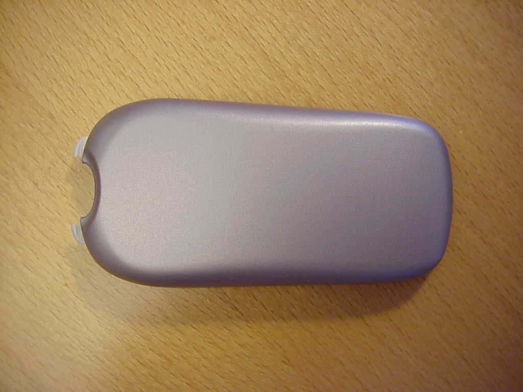
O2OBTP2M100
Jul 16, 2002Motorola Bluetooth Phone Module
Equipment Class
DSS - Part 15 Spread Spectrum Transmitter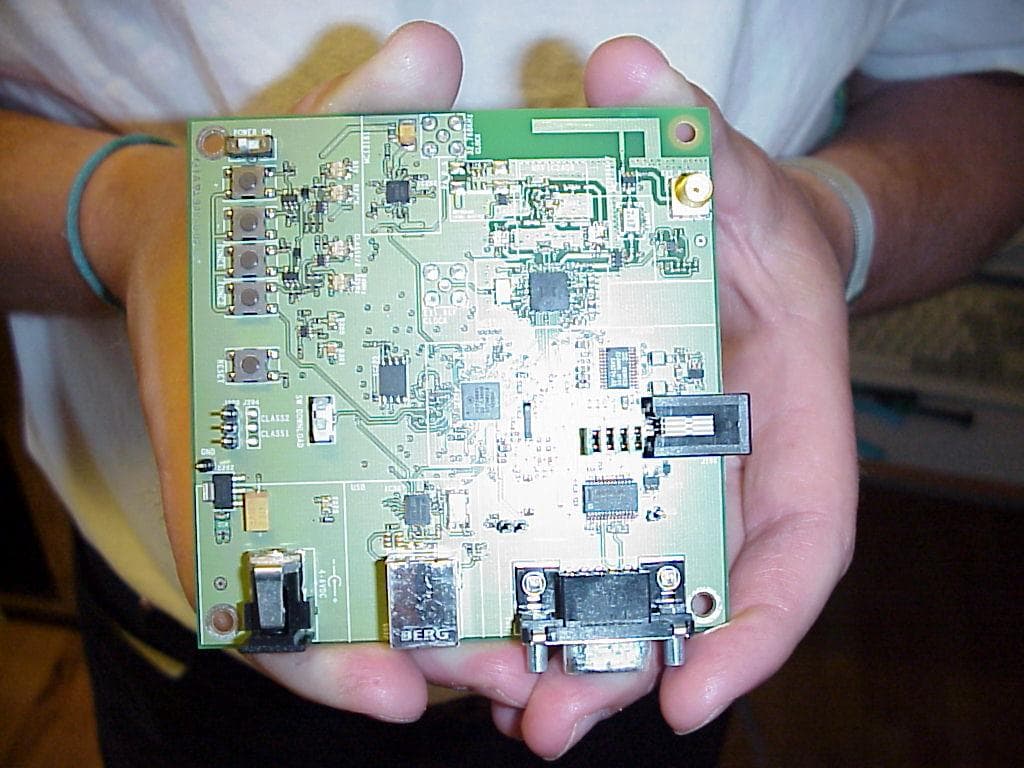
O2OBTDVK100
Jun 27, 2002Bluetooth Developer Kit
Equipment Class
JBP - Part 15 Class B Computing Device Peripheral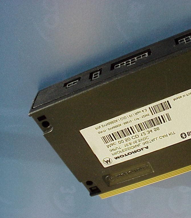
O2OBTHCK100
Apr 23, 2002Bluetooth Hands Free Car Kit
Equipment Class
DSS - Part 15 Spread Spectrum Transmitter