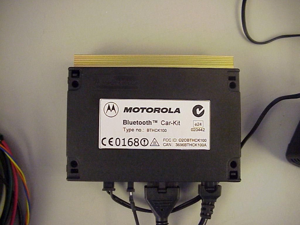
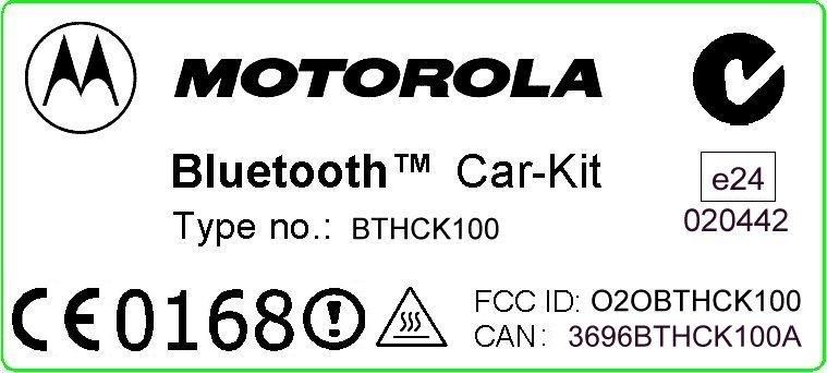
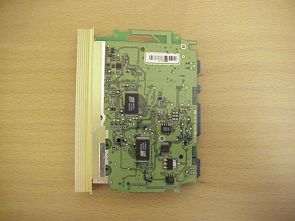
O2OBTHCK100Bluetooth Hands Free Car Kit
Digianswer A/S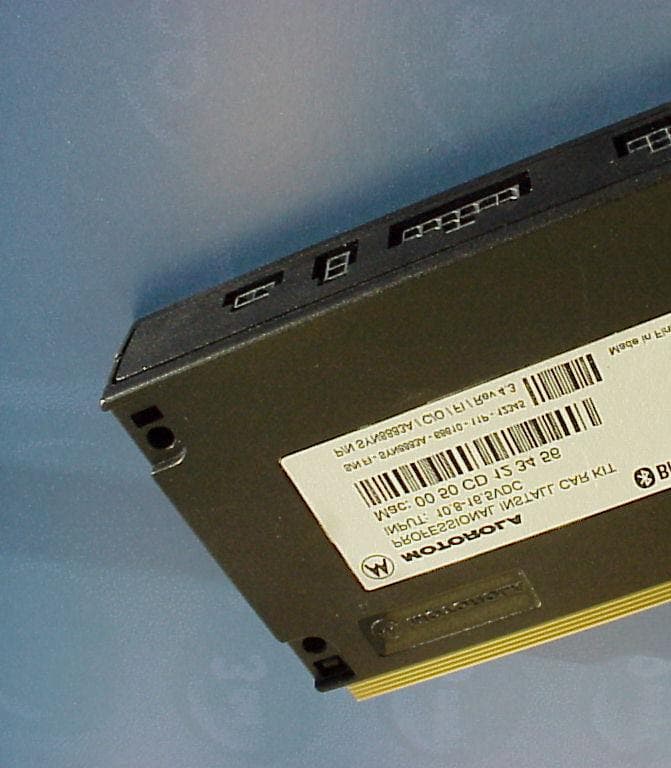
Click to zoom
Application Details
- Equipment Class
- DSS - Part 15 Spread Spectrum Transmitter
- Date of Grant
- Apr 23, 2002
- Application Purpose
- Original Equipment
- Date of Application
- Apr 23, 2002
- Equipment Note
- Bluetooth Hands Free Car Kit
- Frequency Range
- 2402.00000000 - 2480.00000000
- Company
- Digianswer A/S
- Country
- Denmark
Documents & Files
Document Text
Text extracted from the exhibit documents filed with the FCC. Open a document above to read the original.
Users Manual
Bluetooth Car Kit Hands-free System User Guide Compatible with all current mobile phones on the market containing Bluetooth Hands Free Profile or Bluetooth Headset Profile and is trademarks of Motorola, Inc. All Rights reserved. xxxxxxxxx-x 2 V1.0 Description (on the packaging) Bluetooth professional installation hands-free car kit for maximum flexibility Digital Signal Processor (DSP) for full duplex clear audio with noise reduction and echo cancellation Voice recognition (VR) dialing, up to 30 user dependent trained names and numbers. This equipment complies with the R&TTE directive 1999/5/EC and has been provided with the CE mark accordingly. Safety and General Information IMPORTANT INFORMATION ON SAFE AND EFFICIENT OPERATION. READ THIS INFORMATION BEFORE USING YOUR PHONE. Users are not permitted to make changes or modify the device in any way. Changes or modifications not expressly approved by the party responsible for compliance could void the user’s authority to operate the equipment. See 47 CFR Sec. 15.21. This device complies with part 15 of the FCC rules and with RSS-210 / RSS-139 of the Industry Canada. Operation is subject to the following two conditions: (1) This device may not cause harmful interference, and (2) this device must accept any interference received, including interference that may cause undesired operation. See 47 CFR Sec. 15.19(3). In order to comply with FCC RF Exposure requirements, a minimum separation distance of 20 cm must always be maintained between the transmitter antenna and all persons during normal operation. Canada Compliance (Industry Canada) To prevent radio interference to the licensed service, this device is intended to be operated indoors and away from windows to provide maximum shielding. Equipment that is installed outdoors is subject to licensing. In French: Pour empêcher un brouillage radioélectrique au service faisant l'objet d'une licence, cet appareil doit être utilisé à l'interieur et loin des fenêtres afin de founir un écran de blindage maximal. Au cas aù un installation en plain air, le materiel doit faire l'objet d'une licence. European Union (EU) and EFTA This equipment complies with the R&TTE directive 1999/5/EC and has been provided with the CE mark accordingly. Electromagnetic Interference/Compatibility Nearly every electronic device is susceptible to electromagnetic interference (EMI) if inadequately shielded, designed, or otherwise configured for electromagnetic compatibility. Installation The Bluetooth Car Kit is a professional install kit, and should only be installed by a professional. The Car Kit must be connected to a max. 10 A fuse in the car fuse panel to prevent fire or other damages if a short circuit should occur somewhere in the Core Box. 3 V1.0 Installation (refer to figure 1) Note: The Bluetooth Car Kit is a professional install kit, and should only be installed by a professional. Figure 1: Bluetooth Car Kit. The devices not printed in solid black are additional equipment not delivered with the kit. The Core Box provides a digital audio interface to the Portable Digital Cellular Telephone via the Bluetooth link. Its main purpose is to allow safer driving while performing a telephone call at the same time. The Core Box contains the following features: • Digital audio interface with full duplex “Hands Free” function. • Voice recognition. • Voice user interface. • Acoustic echo cancellation. • Noise reduction. • Comfort noise insertion • Optional automatic volume control The Core Box has the following operation limits: Voltage supply: +9V to +16V Operating temperatures: -20°C to +65°C The Core Box has the following connectors: • A power supply connector. • A connector for the Control Panel (including “line out”). • An output for the loudspeaker. • An input for the microphone. • Music mute output • Ignition sense. 4 V1.0 The unit provides "Hands Free" operation for a Portable Digital Cellular Telephone through a Bluetooth radio communication interface. 2. Control Panel The Control Panel is made as the user interface to the Car Kit and thereby to the phone that the user might have stored in his pocket or briefcase. The telephone and the Core Box exchange data digitally via the Bluetooth link. The Control Panel buttons is used for Bluetooth link connection, training of voice recognition and volume control. 3. Loudspeaker The loudspeaker is a small one-way speaker using an ordinary dynamic speaker unit. It connects to the Core Box through a Molex “Microfit” plug. As an option the car stereo speakers can be used with music mute as control signal. 4. Microphone The microphone is uni-directional and of the “electret” type. It connects to the Core Box through a Molex “Microfit” plug. It is fitted with a small bracket for permanent mounting with a screw. It is also supplied with a “clip” for easy mounting in the car environment. The microphone should be positioned at least 30 cm away from the speaker. Mount the microphone in line with your mouth to the sun visor, dashboard or lapel. The microphone should not be exposed to direct air flow from the window or fan. Dress the microphone cable appropriately around vehicle trim. 5. Power cable The power cable is terminated with a Molex “Microfit” connector in one end. The other end is not terminated. The cable contains six conductors. 6. Fuse kit The fuse kit contains: 2 fuses, 2 fuse holders, wires and other mounting hardware. The Car Kit must be connected to a max. 10 A fuse in the car fuse panel to prevent fire or other damages if a short circuit should occur somewhere in the Core Box. Ratings of the fuse kit is 250V 4A. System operation Switching between hands-free and private modes To switch from hands-free to private (or vise-versa), connect/disconnect the Bluetooth link using the blue Bluetooth button on the car kit control panel whilst in a call. Connection/disconnection can also be made from the phone Bluetooth menu. Hands-free speaker volume adjustment Operate the volume bu…
Text truncated - open the document above for the full version.
Operational Description
3. Testobject Data Type Designation: Kind of Device: (optional) Voltage Type: Voltage level: Equipment under Test: Motorola Bluetooth Car Kit DC 12V (9V-16V) Ports 3.1 General EUT Description General product description: Bluetooth is a short-range radio link intended to be a cable replacement between portable and/or fixed electronic devices. Bluetooth operates in the unlicensed ISM Band at 2.4 GHz. In the US a band of 83.5 MHz width is available. In this band, 79 RF channels spaced 1MHz apart are defined. The channel is represented by a pseudo-random hopping sequence through the 79 channels. The channel is devided into time slots, with a nominal slot length of 625μs, where each slot corresponds to different RF hop frequencies. The nominal hop rate is 1600 hops/s. All frequencies are equally used. The average time of occupancy is 0.3797 s within a 30 second period. The symbol rate on the channel is 1 Ms/s. The EUT provides the following ports: temporary antenna connector Enclosure The main components of EUT are listed and described in Chapter 3.2 Page 8 of 59 Testreport Reference: 4_Digi_0102_BTT_FCCa
Test Report
EMC Measurement/Technical Report 4_Digi_0102_BTT_FCCa on 7 Layers AG Borsigstr. 11 40880 Ratingen Germany Note: The following test results relate only to the devices specified in this document. This report shall not be reproduced in parts without the written approval of the testing laboratory. Motorola Bluetooth Car Kit Registergericht - registered in: Ratingen, HRB 3264 Aufsichtratsvorsitzende - Chairman of the Supervisory Board: Dr. Sabine Grobecker Vorstand - Board of Directors: Dr. Wolfgang Dahm Dr. Hans-Jürgen Meckelburg 7 layers AG, Borsigstrasse 11 40880 Ratingen, Germany Phone: +49 (0) 2102 749 0 Fax: +49 (0) 2102 749 350 http://www.7Layers.com Report Reference: TTI-P-G 178/99TTI-P-G 178/99 Table of Contents 0. Summary 0.1 Technical Report Summary 0.2 Measurement Summary 1. Administrative Data 1.1 Testing Laboratory 1.2 Project Data 1.3 Applicant Data 1.4 Manufacturer Data 3. Testobject Data 3.1 General EUT Description 3.2 EUT Main Components 3.3 Ancillary Equipment 3.4 EUT Setups 3.5 Operating Modes 4. Measurement Results Conducted Emissions Occupied Bandwidth Peak Power Output Spurious RF Conducted Emissions 5. Testequipment 6. Foto Report 7. Setup Drawings 3 3 4 6 6 6 6 6 8 8 9 9 9 10 11 -- 11 14 17 29 32 34 35 Spurious RF Radiated Emissions 19 2. Product Labeling 2.1 FCC ID Label 2.2 Location of Label on the EUT 7 7 7 Dwell Time Power Density Channel Separation Processing Gain 23 25 27 28 4.1 4.2 4.3 4.4 4.5 4.6 4.7 4.8 8. Annex Measurement plots25 processing gain measurement report5 Pages Pages Page 2 of 59Testreport Reference: 4_Digi_0102_BTT_FCCa 0 Summary 0.1 Technical Report Summary Type of Authorization Certification for an Intentional Radiator (Frequency Hopping Spread Spectrum) Applicable FCC Rules: Prepared in accordance with the requirements of FCC Rules and Regulations as listed in 47 CFR Ch.1 Parts 0 to 19 (10-1-98 Edition). The following subparts are applicable to the results in this test report. Part 2, Subpart J - Equipment Authorization Procedures, Certification Sections Part 15, Subpart C - Intentional Radiators § 15.201 Equipment authorization requirement § 15.207 Conducted limits § 15.209 Radiated emission limits; general requirements § 15.247 Operation within the bands 902-928 MHz, 2400-2483,5 MHZ and 5725-5850 MHz Summary Test Results: The equipment under test fulfilled the requirements of the applied FCC rules. Note: The tests were selected and performed with reference to the FCC Public Notice DA 00- 705, released March 30, 2000 Page 3 of 59 Testreport Reference: 4_Digi_0102_BTT_FCCa 0.2 Measurement Summary § 15.247 (a) (1) (ii)FCC Part 15, Subpart C ANSI C63.41992 The measurement was performed according to Occupied BandwidthOccupied Bandwidth OP-ModeOP-ModeSetupSetupPortPortFinal ResultFinal Result setup 1op-mode 1temporary antenna connectorpassed setup 1op-mode 2temporary antenna connectorpassed setup 1op-mode 3temporary antenna connectorpassed setup 1op-mode 4temporary antenna connectorpassed setup 1op-mode 5temporary antenna connectorpassed § 15.247 (b) (1)FCC Part 15, Subpart C FCC §15.3110-1-1998 The measurement was performed according to Peak Power OutputPeak Power Output OP-ModeOP-ModeSetupSetupPortPortFinal ResultFinal Result setup 1op-mode 1temporary antenna connectorpassed setup 1op-mode 2temporary antenna connectorpassed setup 1op-mode 3temporary antenna connectorpassed setup 1op-mode 4temporary antenna connectorpassed setup 1op-mode 5temporary antenna connectorpassed § 15.247 (c)FCC Part 15, Subpart C FCC §15.3110-1-1998 The measurement was performed according to Spurious RF Conducted EmissionsSpurious RF Conducted Emissions OP-ModeOP-ModeSetupSetupPortPortFinal ResultFinal Result setup 1op-mode 1temporary antenna connectorpassed setup 1op-mode 2temporary antenna connectorpassed setup 1op-mode 3temporary antenna connectorpassed § 15.247 (c), §15.35 (b), § 15.209FCC Part 15, Subpart C ANSI C63.41992 The measurement was performed according to Spurious Radiated EmissionsSpurious Radiated Emissions OP-ModeOP-ModeSetupSetupPortPortFinal ResultFinal Result setup 2op-mode 1enclosurepassed setup 2op-mode 2enclosurepassed setup 2op-mode 3enclosurepassed § 15.247 (g)FCC Part 15, Subpart C FCC §15.3110-1-1998 The measurement was performed according to Dwell TimeDwell Time OP-ModeOP-ModeSetupSetupPortPortFinal ResultFinal Result setup 1op-mode 4temporary antenna connectorpassed setup 1op-mode 5temporary antenna connectorpassed § 15.247 (g)FCC Part 15, Subpart C Page 4 of 59 Testreport Reference: 4_Digi_0102_BTT_FCCa FCC §15.3110-1-1998 The measurement was performed according to Power DensityPower Density OP-ModeOP-ModeSetupSetupPortPortFinal ResultFinal Result setup 1op-mode 4temporary antenna connectorpassed setup 1op-mode 5temporary antenna connectorpassed § 15.247 (a) (1)FCC Part 15, Subpart C FCC §15.3110-1-1998 The measurement was performed according to Channel SeparationChannel Separation OP-ModeOP-ModeSetupSetupPortPortFinal ResultFinal Result setup 1op-mode 6temporary antenna connectorpassed § 15.247 (f)FCC Part 15, Subpart C FCC §15.3110-1-1998 The measurement was performed according to Processing GainProcessing Gain OP-ModeOP-ModeSetupSetupPortPortFinal ResultFinal Result setup 3see annextemporary antenna connectorpassed Responsible for Accreditation Scope: Responsible for Test Report: Page 5 of 59Testreport Reference: 4_Digi_0102_BTT_FCCa 1. Administrative Data 1.1 Testing Laboratory Company Name: Address: The test facility is also accredited by the following accreditation organisation: Responsible for Accreditation Scope: 7 Layers AG Borsigstr. 11 40880 Ratingen Germany DAR-Registration no. TTI-P-G 178/99 Dipl.-Ing Bernhard Retka Dipl.-Ing Arndt Stöcker This facility has been fully described in a report submitted to the FCC and accepted in a letter dated February 07, 2000 under the registration number 96716. - Deutscher Akkreditierungs Rat 16.01.02 Dipl.-Ing. Thomas Hoell 22.01.02 16.01.02 - 22.01.02 Responsible for testing and report Receip…
Text truncated - open the document above for the full version.
Test Report
Note : This annex is only valid in combination with the above mentioned test report. The following results relate only to the devices specified in that report. This annex shall not be reproduced in parts without the written approval of the testing laboratory. Annex to Test Report 4_DIGI_0102_BTT_FCCa Processing gain Measurement for Motorola Bluetooth Car Kit Test Laboratory: 7 layers AG Borsigstrasse. 11 D-40880 Ratingen Germany Annex to test report 4_Digi_0102_BTT_FCCa Page 2 of 5 pages Introduction This report describes the results of the processing gain measurement for the Motorola Bluetooth Car Kit using the FCC CW jamming margin method. Requirement Hybrid systems that employ a combination of both direct sequence and frequency hopping modulation techniques shall achieve a processing gain of at least 17 dB from the combined techniques. Modification of measurement method Despreading is accomplished by correlating the received bit stream with the bit pattern of the access code. Then with the value of the correlator output will be decided if the access code is valid or not. That means if the access code is not valid a “bit error” occurs for the Bluetooth device. For this reason in CW jamming margin method the ratio of invalid access codes (IACR) is used instead of the BER. Another reason to use this criteria is the fact, that the Bluetooth technology uses the access code to find the correct sampling point. That means if the access code cannot be found, all other bits in the transmission cannot be sampled successfully. System loss In the formula to calculate the processing gain the term system loss appears. In Bluetooth there are two major causes for the system loss: 1. The non optimal sampling time. The CW jamming method assumes that the optimal sampling time as determined before, in fact, as described above, will be determined via the access code. 2. Loss due to attenuation in the RF part. Although these two points produce a system loss which will be much greater than 2 dB, we took that value for the calculation, because this is the maximum which will be accepted by the FCC. Annex to test report 4_Digi_0102_BTT_FCCa Page 3 of 5 pages Measurement Set-up To measure the IACR the following test set-up was used: 7 24 10 5 3 RF In/Out Step Attenuator High Pass Signal Generator RF Switch Fixed Attenuator 1 6 dB Coupler 6 dB CouplerSignaling device 6 8 912 13 Device under test Spectrum Analyser Noise Source PowerAmplifier Fixed Attenuator 3 Fixed Attenuator 11 RF block diagram Note: For detailed information about the equipment please see test equipment list For the measurement of the invalid access codes a special test program was used. It was installed on the laptop (HP Omnibook) and controlled the Motorola Bluetooth Car Kit. In the result the number of invalid access codes for a packet of 255 transmissions is given. For this test 200 packets (51000 bursts) were measured. For the selected IACR of 0.1% it means that 51 access codes are not valid. The level of the wanted signal was set for all single measurements to –43,8 dBm. Measurement Results S/N Measurement The measurement for S/N was performed by adding noise to the wanted signal. The noise level was adjusted until the IACR reached 0.1%. With this measurement configuration the S/N ratio was 12,84 dB. Annex to test report 4_Digi_0102_BTT_FCCa Page 4 of 5 pages Jammer-Signal Measurement The jammer signal was stepped in 50 kHz steps over the receiving channel. For every step the jammer level was adjusted until the IACR was 0.1 %. The ratio between wanted signal power and the jammer power at the RF input of the device is the required Jammer to Signal ratio (JSR). With this measurement configuration the Jammer-signal measurement results are as follows: Disregarding the marked data points (-400, -350, -300, -250 kHz) the worst data point is at -450 kHz (Jammer-signal –54,6 dBm) with a Jammer / Signal value of –10,8 dB. Processing gain calculation With these values the processing gain for the DSS part of the system is calculated to: Mj = JSR = -10,8 dB S/N = 12,84 dB Gp = S/N + Mj + Lsys = 12,84 dB– 10,8 dB+ 2,0 dB= 4,04 dB The processing gain for FHSS part is calculated as: 10 * log 32 = 15 dB (32 hopping channels in hybrid mode) This means for the total processing gain of the hybrid system: 15 dB + 4,04 dB = 19,04 dB This is above the minimum value of 17 dB stated in FCC rules. The device passes the requirement of this clause. Jammer Offset/kHz Jammer-Signal (dBm) -500-54,2 -450-54,6 -400-55,6 -350-55,8 -300-55,4 -250-54,8 -200-54,0 -150-53,7 -100-52,5 -50-52,5 0-51,7 50-52,7 100-52,6 150-53,7 200-53,3 250-53,8 300-52,9 350-53,9 400-53,6 450-53,9 500-53,6 -58,0 -56,0 -54,0 -52,0 -50,0 -48,0 -46,0 -44,0 -42,0 -40,0 -500-400-300-200-1000100200300400500 Jammer Offset /kHz dB Jammer-Signal (dBm) Annex to test report 4_Digi_0102_BTT_FCCa Page 5 of 5 pages Test equipment noSingle DevicesTypeSerial NoManufacturer 2Signaling device: Motorola Bluetooth Car Kit--Digianswer 3Attenuator, 3 dBModel 4T-3D9355Weinschel 3Attenuator, 3 dB1W-393459- 4Broadband Resist. Power Divider N1506A / 93459LM390Weinschel 5Broadband Resist. Power Divider SMA1515 / 93459LN673Weinschel 6Broadband Amplifier 45MHz-27GHzJS4-00102600-42-619368Miteq 7High Pass Filter5HC2700/12750-1.5-KK9942012Trilithic 8Noise EmitterCNE III99/016York 9RF Step AttenuatorRSP833695/001Rohde & Schwarz 10Signal GeneratorSMIQ 03B1125.5555.03Rohde & Schwarz 11Attenuator 10 dB2BG9126Weinschel 11Attenuator 20 dB4T-20F1304Weinschel 12Manual Switch--7 layers 13EMI AnalyzerFSP1093.4495.03Rohde & Schwarz
Test Report
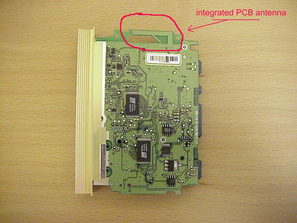
Marianne Bosley From:Marianne Bosley Sent:Monday, April 08, 2002 6:33 PM To:Marianne Bosley Subject:FW: Metrak #12069 FCC ID:O2OBTHCK100 -----Original Message----- From: Marianne Bosley To: '[email protected]' Sent: 4/8/2002 6:31 PM Subject: Metrak #12069 FCC ID:O2OBTHCK100 Hello Mr. Ringtved, The technical review has been completed, and the engineer has the following issues: 1. FCC test procedures require a slow sweep (1sec/3kHz) for the psd measurement. Please justify the use of a fast (i/e., coupled) sweep for this measurement (we have asked in the past that you provide this justification. Please include it in future test reports). 2. Please verify that the receiver uses an input bandwidth equivalent to the transmitted bandwidth, per Section 15.247(a)(1). The fact that the rx hops in sync with the transmitted signal can be deduced from the block diagram, however, the input filter bandwidth is not indicated. 3. Please address Section 15.203. The antenna gain is provided, however, no other info re the antenna is given. What kind of antennas is it? Is it etched on the pcb? 4. Please address Sections 15.247(g) and (h). Typically, an info sheet is provided that addresses these sections, but I did not receive one for this application. Please respond with answers to me, and I will forward for a final review. Any questions, please let me know. Have a good evening. Regards, Marianne
Test Report
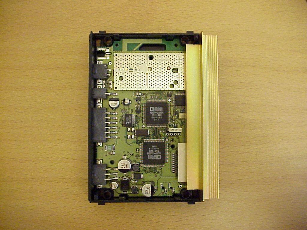
Marianne Bosley From:Ringt ved Tom-TOMRI N1 [[email protected]] Sent:Friday, April 12, 2002 4:39 AM To:'Marianne Bosley' Subject:RE: Metrak #12069 FCC ID:O2OBTHCK100 Hi Marianne answers to your questions: 1) the transmitter is only active for some milliseconds on one channel. Then you have to activate it again. Using such a long sweep time you would get a result with many interruptions. Therefore we use a fast sweep in maxhold function and activate the EUT until the measurement curve has stabilized. 2) bandwidth of the input filter is 1 MHz. This has now been added to the block diagram - please see pdf-file "block description - Motorola Bluetooth Car Kit1.3.pdf" 3) antenna is an PCB F-antenna type - please see attached file: "BTCK antenna.jpg" 4) please see attached pdf-file "Additional_Declaration_FCC_15_247_01_02_09.PDF" regards - Tom NOTE: NEW DIRECT PHONE NUMBER ! -------------------------------------------------------- Tom Ringtved e-mail: [email protected] / B.Sc. E. Prod. Eng. [email protected] Type appr./Cert. Manager Direct: +45 70 24 14 25 Digianswer A/S Tel : +45 96 71 00 00 Skalhuse 5 Fax : +45 98 35 00 52 DK-9240 Nibe Denmark http://www.digianswer.com -------------------------------------------------------- -----Original Message----- From: Marianne Bosley [mailto:[email protected]] Sent: 9. april 2002 00:31 To: '[email protected]' Subject: Metrak #12069 FCC ID:O2OBTHCK100 Hello Mr. Ringtved, The technical review has been completed, and the engineer has the following issues: 1. FCC test procedures require a slow sweep (1sec/3kHz) for the psd measurement. Please justify the use of a fast (i/e., coupled) sweep for this measurement (we have asked in the past that you provide this justification. Please include it in future test reports). 2. Please verify that the receiver uses an input bandwidth equivalent to the transmitted bandwidth, per Section 15.247(a)(1). The fact that the rx hops in sync with the transmitted signal can be deduced from the block diagram, however, the input filter bandwidth is not indicated. 3. Please address Section 15.203. The antenna gain is provided, however, no other info re the antenna is given. What kind of antennas is it? Is it etched on the pcb? 4. Please address Sections 15.247(g) and (h). Typically, an info sheet is provided that addresses these sections, but I did not receive one for this application. Please respond with answers to me, and I will forward for a final review. Any questions, please let me know. Have a good evening. Regards, Marianne Additional_Declaration _FCC_15_... BTCK antenna.jpgblock description - Motorola B...
Test Setup Photos
6. Foto Report Picture1Setup for radiated emission tests below 1 GHz: Picture2Setup for radiated emission tests below 1 GHz (detailed view): Page 32 of 59Testreport Reference: 4_Digi_0102_BTT_FCCa Picture3Setup for radiated emission tests above 1 GHz: Picture4Setup for radiated emission tests above 1 GHz (detailed view): Page 33 of 59Testreport Reference: 4_Digi_0102_BTT_FCCa
Contact Information
Applicant
Jorgen Holst(Functional Manager, Platform & IT)
Test Firm
7layers AGRobert Machulec
Technical Specifications
| # | Rule Parts | Frequency Range | Power Output |
|---|---|---|---|
| 1 | 15C | 2.40 GHz - 2.48 GHz | 3.00 mW |
Other Applications from Digianswer A/S
O2O13192-EVB
Sep 21, 2004WPAN Transceiver
Equipment Class
DTS - Digital Transmission System
O2O13192-SARD
Aug 24, 2004IEEE 802.15.4 Transceiver
Equipment Class
DTS - Digital Transmission System
O2OBTDVK110
Jan 22, 2003Bluetooth Developer Kit
Equipment Class
DSS - Part 15 Spread Spectrum Transmitter
O2OBTP2M100
Jul 16, 2002Motorola Bluetooth Phone Module
Equipment Class
DSS - Part 15 Spread Spectrum Transmitter
O2OBTDVK100
Jun 27, 2002Bluetooth Developer Kit
Equipment Class
JBP - Part 15 Class B Computing Device Peripheral