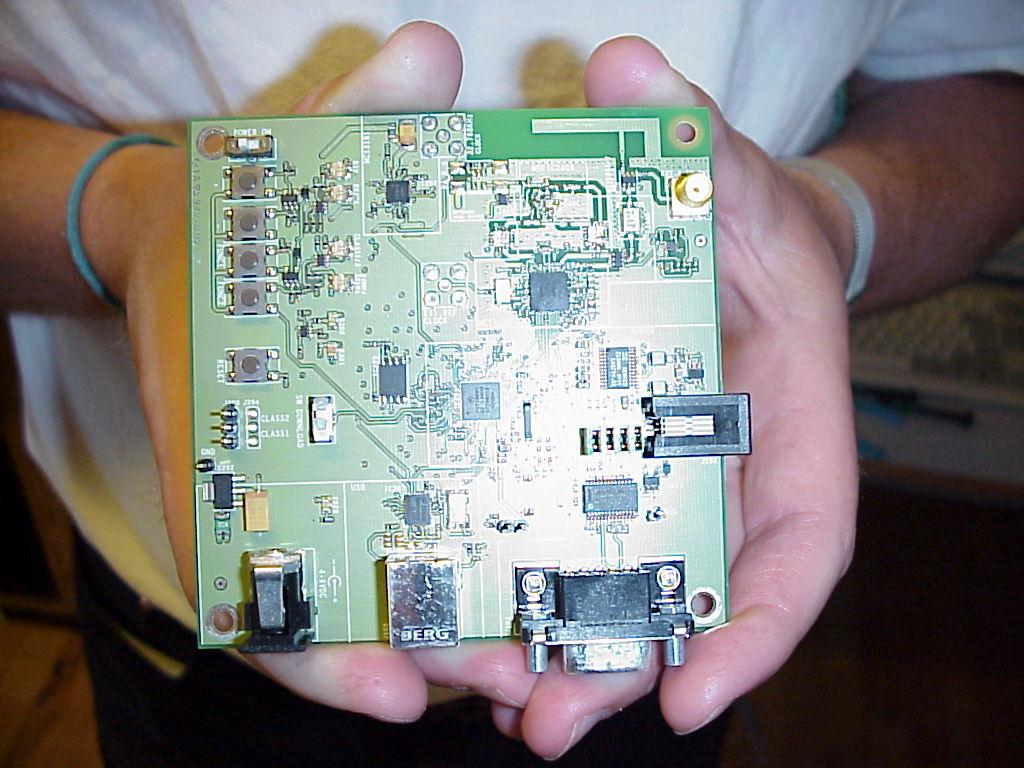
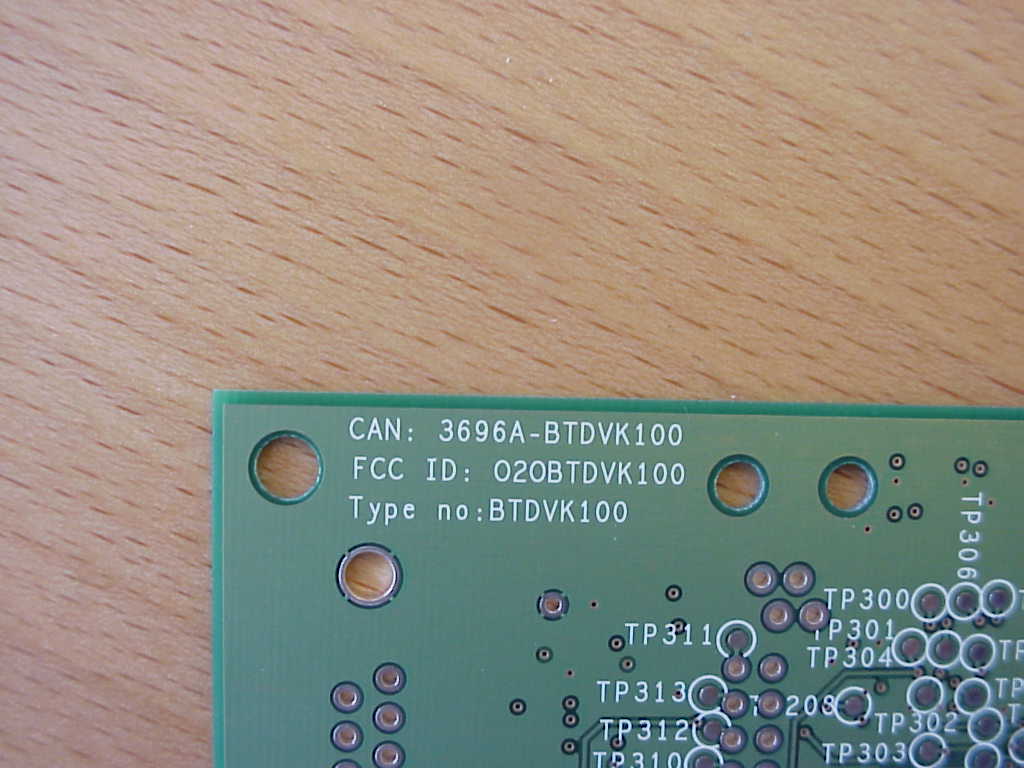
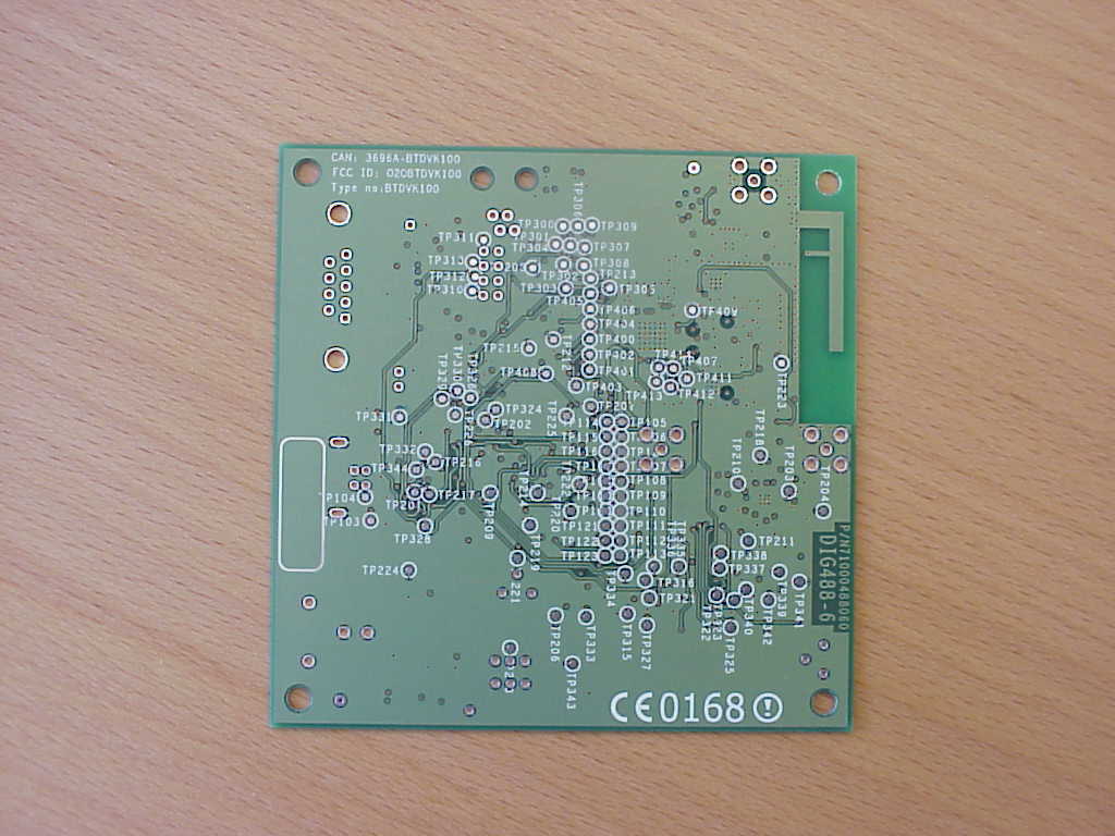
O2OBTDVK100Bluetooth Developer Kit
Digianswer A/S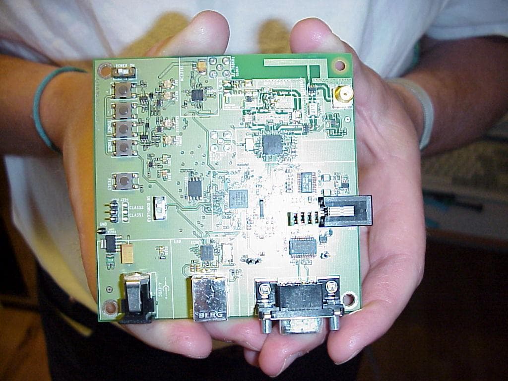
Click to zoom
Application Details
- Equipment Class
- JBP - Part 15 Class B Computing Device Peripheral
- Date of Grant
- Jun 27, 2002
- Application Purpose
- Original Equipment
- Date of Application
- Jun 27, 2002
- Equipment Note
- Bluetooth Developer Kit
- Company
- Digianswer A/S
- Country
- Denmark
Documents & Files
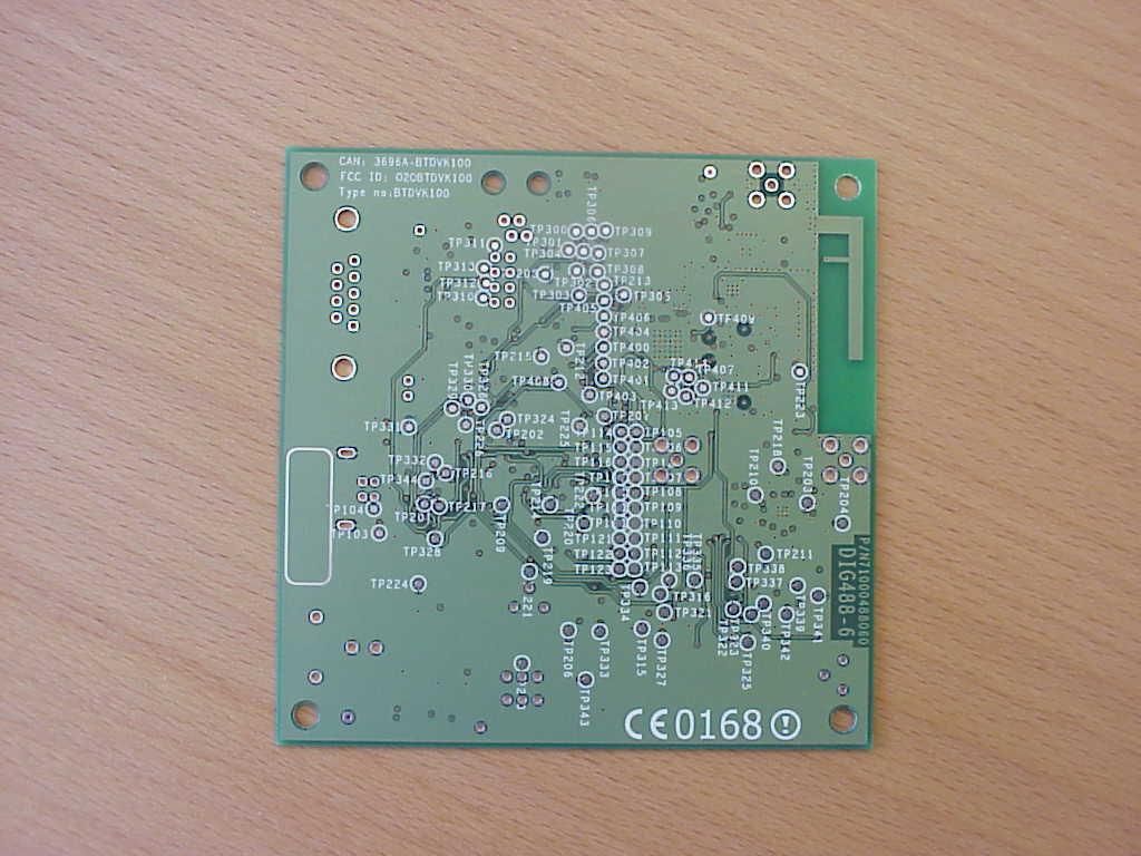
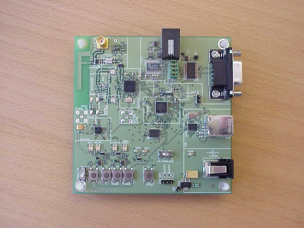
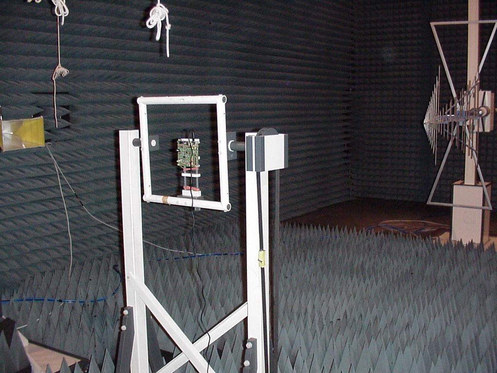
Document Text
Text extracted from the exhibit documents filed with the FCC. Open a document above to read the original.
Users Manual
94001480000 Rev. 2.0, 2002-05-29 Bluetooth Development Kit User’s Guide Motorola reserves the right to make changes without further notice to any products herein. Motorola makes no warranty, representation or guarantee regarding the suitability of its products for any particular purpose, nor does Motorola assume any liability arising out of the application or use of any product or circuit, and specifically disclaims any and all liability, including without limitation consequential or incidental damages. “Typical” parameters which may be provided in Motorola data sheets and/or specifications can and do vary in different applications and actual performance may vary over time. All operating parameters, including “Typicals” must be validated for each customer application by customer’s technical experts. Motorola does not convey any license under its patent rights nor the rights of others. Motorola products are not designed, intended, or authorized for use as components in systems intended for surgical implant into the body, or other applications intended to support life, or for any other application in which the failure of the Motorola product could create a situation where personal injury or death may occur. Should Buyer purchase or use Motorola products for any such unintended or unauthorized application, Buyer shall indemnify and hold Motorola and its officers, employees, subsidiaries, affiliates, and distributors harmless against all claims, costs, damages, and expenses, and reasonable attorney fees arising out of, directly or indirectly, any claim of personal injury or death associated with such unintended or unauthorized use, even if such claim alleges that Motorola was negligent regarding the design or manufacture of the part. The Bluetooth trademarks are owned by their proprietor and used by Motorola, Inc., under license. All other product or service names are the property of their respective owners. © Motorola, Inc. 2002. Motorola and are registered trademarks of Motorola, Inc. Motorola, Inc. is an Equal Opportunity/Affirmative Action Employer. How to reach us: USA/EUROPE/Locations Not Listed: Motorola Literature Distribution; P.O. Box 5405, Denver, Colorado, 80217. 1–303–675–2140 or 1–800–441–2447 JAPAN: Motorola Japan Ltd.; SPS, Technical Information Center, 3–20–1, Minami–Azabu, Minato–ku, Tokyo 106–8573 Japan. 81–3–3440–3569 ASIA/PACIFIC: Motorola Semiconductors H.K. Ltd., Silicon Harbour Centre, 2 Dai King Street, Tai Po Industrial Estate, Tai Po, N.T., Hong Kong. 852–26668334 Technical Information Center: 1–800–521–6274 HOME PAGE: http://www.motorola.com/semiconductors/ © Copyright Motorola, Inc., 2002 MOTOROLAContentsiii Motorola Confidential Proprietary, NDA Required / Preliminary Chapter 1 Introduction 1.1About This Guide . . . . . . . . . . . . . . . . . . . . . . . . . . . . . . . . . . . . . . . . . . . . . . . . . . . . . . 1-1 1.2Additional Documents . . . . . . . . . . . . . . . . . . . . . . . . . . . . . . . . . . . . . . . . . . . . . . . . . . 1-2 1.3Downloads and Support . . . . . . . . . . . . . . . . . . . . . . . . . . . . . . . . . . . . . . . . . . . . . . . . . 1-3 1.4Unpacking . . . . . . . . . . . . . . . . . . . . . . . . . . . . . . . . . . . . . . . . . . . . . . . . . . . . . . . . . . . . 1-3 1.5System Requirements . . . . . . . . . . . . . . . . . . . . . . . . . . . . . . . . . . . . . . . . . . . . . . . . . . . 1-3 1.6Acronyms and Abbreviations . . . . . . . . . . . . . . . . . . . . . . . . . . . . . . . . . . . . . . . . . . . . . 1-4 Chapter 2 Product Overview 2.1Block Diagram . . . . . . . . . . . . . . . . . . . . . . . . . . . . . . . . . . . . . . . . . . . . . . . . . . . . . . . . 2-5 2.2Interfaces. . . . . . . . . . . . . . . . . . . . . . . . . . . . . . . . . . . . . . . . . . . . . . . . . . . . . . . . . . . . . 2-5 2.3Applications . . . . . . . . . . . . . . . . . . . . . . . . . . . . . . . . . . . . . . . . . . . . . . . . . . . . . . . . . . 2-6 2.4ICs . . . . . . . . . . . . . . . . . . . . . . . . . . . . . . . . . . . . . . . . . . . . . . . . . . . . . . . . . . . . . . . . . . 2-6 2.5Software Tools . . . . . . . . . . . . . . . . . . . . . . . . . . . . . . . . . . . . . . . . . . . . . . . . . . . . . . . . 2-6 2.5.1Bluetooth HCI Terminal . . . . . . . . . . . . . . . . . . . . . . . . . . . . . . . . . . . . . . . . . . . . . . 2-7 2.5.2Configuration Manager . . . . . . . . . . . . . . . . . . . . . . . . . . . . . . . . . . . . . . . . . . . . . . . 2-7 2.5.3DemoBench . . . . . . . . . . . . . . . . . . . . . . . . . . . . . . . . . . . . . . . . . . . . . . . . . . . . . . . 2-7 Chapter 3 Setup 3.1Setting Up Board . . . . . . . . . . . . . . . . . . . . . . . . . . . . . . . . . . . . . . . . . . . . . . . . . . . . . . 3-9 3.2Running UART . . . . . . . . . . . . . . . . . . . . . . . . . . . . . . . . . . . . . . . . . . . . . . . . . . . . . . . . 3-9 3.3Running USB . . . . . . . . . . . . . . . . . . . . . . . . . . . . . . . . . . . . . . . . . . . . . . . . . . . . . . . . . 3-9 Chapter 4 Hardware 4.1Signal and Connection Descriptions . . . . . . . . . . . . . . . . . . . . . . . . . . . . . . . . . . . . . . . 4-11 4.2Environmental. . . . . . . . . . . . . . . . . . . . . . . . . . . . . . . . . . . . . . . . . . . . . . . . . . . . . . . . 4-12 4.3Mechanical . . . . . . . . . . . . . . . . . . . . . . . . . . . . . . . . . . . . . . . . . . . . . . . . . . . . . . . . . . 4-12 4.4Electrical . . . . . . . . . . . . . . . . . . . . . . . . . . . . . . . . . . . . . . . . . . . . . . . . . . . . . . . . . . . . 4-12 4.4.1Power Supply . . . . . . . . . . . . . . . . . . . . . . . . . . . . . . . . . . . . . . . . . . . . . . . . . . . . . 4-13 4.4.2Reset Circuit . . . . . . . . . . . . . . . . . . . . . . . . . . . . . . . . . . . . . . . . . . . . . . . . . . . . . . 4-13 4.4.3Clocks . . . . . . . . . . . . . . . . . . . . . . . . . . . . . . . . . . . . . . . . . . . . . . . . . . . . . . . . . . . 4-13 4.4.4Memory…
Text truncated - open the document above for the full version.
Test Report
EMC Measurement/Technical Report 4_DIGI_0502_ERF_FCCb on 7 Layers AG Borsigstr. 11 40880 Ratingen Germany Note: The following test results relate only to the devices specified in this document. This report shall not be reproduced in parts without the written approval of the testing laboratory. Motorola Bluetooth™ Development Kit BTDVK100 Registergericht - registered in: Ratingen, HRB 3264 Aufsichtratsvorsitzende - Chairman of the Supervisory Board: Dr. Sabine Grobecker Vorstand - Board of Directors: Dr. Wolfgang Dahm Dr. Hans-Jürgen Meckelburg 7 layers AG, Borsigstrasse 11 40880 Ratingen, Germany Phone: +49 (0) 2102 749 0 Fax: +49 (0) 2102 749 350 http://www.7Layers.com Report Reference: Table of Contents 0. Summary 0.1 Technical Report Summary 0.2 Measurement Summary 1. Administrative Data 1.1 Testing Laboratory 1.2 Project Data 1.3 Applicant Data 1.4 Manufacturer Data 3. Testobject Data 3.1 General EUT Description 3.2 EUT Main Components 3.3 Ancillary Equipment 3.4 EUT Setups 3.5 Operating Modes 4. Measurement Results Conducted Emissions Occupied Bandwidth Output Power Spurious Emissions Conducted 5. Testequipment 6. Foto Report 7. Setup Drawings 3 3 4 5 5 5 5 5 7 7 8 8 8 9 10 10 15 17 20 Spurious Emissions Radiated12 2. Product Labeling 2.1 FCC ID Label 2.2 Location of Label on the EUT 6 6 6 Dwell Time Power Density Channel Separation Processing Gain 4.1 4.2 Page 2 of 20Testreport Reference: 4_DIGI_0502_ERF_FCCb 0 Summary 0.1 Technical Report Summary Type of Authorization: Certification for an Unintentional Radiator (Class B digital device) Applicable FCC Rules: Prepared in accordance with the requirements of FCC Rules and Regulations as listed in 47 CFR Ch.1 Parts 0 to 19 (10-1-98 Edition). The following subparts are applicable to the results in this test report. Part 2, Subpart J - Equipment Authorization Procedures, Certification Sections Part 15, Subpart B - Unintentional Radiators § 15.101 Equipment authorization requirement § 15.107 Conducted limits § 15.109 Radiated emission limits Summary Test Results: The equipment under test fulfilled the requirements of the applied FCC rules. Page 3 of 20Testreport Reference: 4_DIGI_0502_ERF_FCCb 0.2 Measurement Summary §15.107FCC Part 15, Subpart B ANSI C63.41992The measurement was performed according to Conducted Emissions (AC Power Line)Conducted Emissions (AC Power Line) OP-ModeOP-ModeSetupSetupPortPortFinal ResultFinal Result setup 1op-mode 1AC portpassed §15.31, §15.109FCC Part 15, Subpart B ANSI C63.41992The measurement was performed according to Spurious Radiated EmissionsSpurious Radiated Emissions OP-ModeOP-ModeSetupSetupPortPortFinal ResultFinal Result setup 1op-mode 1enclosurepassed Responsible for Accreditation Scope: Responsible for Test Report: Page 4 of 20Testreport Reference: 4_DIGI_0502_ERF_FCCb 1. Administrative Data 1.1 Testing Laboratory Company Name: Address: The test facility is also accredited by the following accreditation organisation: Responsible for Accreditation Scope: 7 Layers AG Borsigstr. 11 40880 Ratingen Germany DAR-Registration no. TTI-P-G 178/99 Dipl.-Ing Bernhard Retka Dipl.-Ing Arndt Stöcker This facility has been fully described in a report submitted to the FCC and accepted in a letter dated February 07, 2000 under the registration number 96716. - Deutscher Akkreditierungs Rat 11.06.2002 Dipl. Ing. Thomas Hoell 26.06.2002 25.06.-26.06.2002 Responsible for Test Report: Receipt of EUT: Date of Test(s): Date of Report: 1.2 Project Data Digianswer A/S Tom Ringtved Skalhuse 5 DK-9240 Nibe Denmark please see Applicant data 1.4 Manufacturer Data Company Name: Address: Contact Person: Company Name: Address: Contact Person: 1.3 Applicant Data Page 5 of 20Testreport Reference: 4_DIGI_0502_ERF_FCCb 2.0 Product Labeling 2.1 FCC ID Label: At the time of the test report there was no FCC label available. 2.2 Location of Label on the EUT: see above Page 6 of 20Testreport Reference: 4_DIGI_0502_ERF_FCCb 3. Testobject Data Type Designation: Kind of Device: (optional) Voltage Type: Voltage level: Equipment under Test: BTDVK100 Bluetooth transceiver Motorola Bluetooth™ Development Kit DC 5 V Ports 3.1 General EUT Description General product description: Bluetooth is a short-range radio link intended to be a cable replacement between portable and/or fixed electronic devices. Bluetooth operates in the unlicensed ISM Band at 2.4 GHz. In the US a band of 83.5 MHz width is available. In this band, 79 RF channels spaced 1MHz apart are defined. The channel is represented by a pseudo-random hopping sequence through the 79 channels. The channel is devided into time slots, with a nominal slot length of 625μs, where each slot corresponds to different RF hop frequencies. The nominal hop rate is 1600 hops/s. All frequencies are equally used. The average time of occupancy is 0.3797 s within a 30 second period. The symbol rate on the channel is 1 Ms/s. The EUT provides the following ports: AC port Enclosure The main components of EUT are listed and described in Chapter 3.2 Page 7 of 20Testreport Reference: 4_DIGI_0502_ERF_FCCb Short Description Equipment under Test Type Designation 3.2 EUT Main components: Type, S/N, Short Descriptions etc. used in this Test Report HW StatusSW StatusSerial No.Date of Receipt 8000048800 0_R06 2.0EUT code 34070a0111.06.2002BTDVK100Bluetooth Development Kit EUT A EUT A is equipped with an internal antenna. NOTE: The short description is used to simplify the identification of the EUT in this test report 3.3 Ancillary Equipment Short Description Equipment under TestType DesignationHW StatusSW StatusSerial No.FCC Id For the purposes of this test report, ancillary equipment is defined as equipment which is used in conjunction with the EUT to provide additional operational and control features to the EUT. It is necessary to configure the system in a typical fashion, as a customer would normally use it. AE 5MouseM-S34--F13490N5BH 00D90 DZL211029 AE 4MonitorSamsung Sync Master 700p plus --SE17H3MK30 5316L CSE7839…
Text truncated - open the document above for the full version.
Test Report
Registergerichth registered in:Vorstandh Board of Directors:7 layers AG, Borsigstrasse 11 Ratingen HRB 3264Dr. Wolfgang Dahm40880 Ratingen, Germany AufsichtsratsvorsitzendehDr. Hans-Jürgen MeckelburgPhone: +49 (0) 2102 749 0 Chairman of the Supervisory Board:Fax: +49 (0) 2102 749 350 Dr. Sabine Grobeckerwww.7layers.com Annex Additional declaration part according FCC 15.247 for Bluetooth TM Devices Version: 2002-06-01 Annex - Additional declaration part according FCC 15.247 for Bluetooth devices Page 2 of 5 pages 1 Output power and channel separation of a Bluetooth device in the different operating modes: The different operating modes (data-mode, acquisition-mode) of a Bluetooth device don’t influence the output power and the channel spacing. There is only one transmitter which is driven by identical input parameters concerning these two parameters. Only a different hopping sequence will be used. For this reason the check of these RF parameters in one op-mode is sufficient. 2 Frequency range of a Bluetooth device: Hereby we declare that the maximum frequency of this device is: 2402 – 2480 MHz. This is according the Bluetooth Core Specification (+ critical errata) for devices which will be operated in the USA. This was checked during the Bluetooth Qualification tests (Test Case: TRM/CA/04-E). Other frequency ranges ( e.g. for Spain, France, Japan) which are allowed according the Core Specification are not supported by this device. 3 Co-ordination of the hopping sequence in data mode to avoid simultaneous occupancy by multiple transmitters: Bluetooth units which want to communicate with other units must be organised in a structure called piconet. This piconet consist of max. 8 Bluetooth units. One unit is the master the other seven are the slaves. The master co-ordinates frequency occupation in this piconet for all units. As the master hop sequence is derived from its BD address which is unique for each Bluetooth device, additional masters intending to establish new piconets will always use different hop sequences. 4 Example of a hopping sequence in data mode: Example of a 79 hopping sequence in data mode: 40, 21, 44, 23, 42, 53, 46, 55, 48, 33, 52, 35, 50, 65, 54, 67, 56, 37, 60, 39, 58, 69, 62, 71, 64, 25, 68, 27, 66, 57, 70, 59, 72, 29, 76, 31, 74, 61, 78, 63, 01, 41, 05, 43, 03, 73, 07, 75, 09, 45, 13, 47, 11, 77, 15, 00, 64, 49, 66, 53, 68, 02, 70, 06, 01, 51, 03, 55, 05, 04 Annex - Additional declaration part according FCC 15.247 for Bluetooth devices Page 3 of 5 pages 5 Equally average use of frequencies in data mode and behaviour for short transmissions: The generation of the hopping sequence in connection mode depends essentially on two input values: 1. LAP/UAP of the master of the connection 2. Internal master clock The LAP (lower address part) are the 24 LSB’s of the 48 BD_ADDRESS. The BD_ADDRESS is an unambiguous number of every Bluetooth unit. The UAP (upper address part) are the 24 MSB’s of the 48 BD_ADDRESS. The internal clock of a Bluetooth unit is derived from a free running clock which is never adjusted and is never turned off. For synchronisation with other units only offset are used. It has no relation to the time of the day. Its resolution is at least half the RX/TX slot length of 312.5 μs. The clock has a cycle of about one day (23h30). In most case it is implemented as 28 bit counter. For the deriving of the hopping sequence the entire LAP (24 bits), 4 LSB’s (4 bits) (Input 1) and the 27 MSB’s of the clock (Input 2) are used. With this input values different mathematical procedures (permutations, additions, XOR- operations) are performed to generate the sequence. This will be done at the beginning of every new transmission. Regarding short transmissions the Bluetooth system has the following behaviour: The first connection between the two devices is established, a hopping sequence was generated. For transmitting the wanted data the complete hopping sequence was not used. The connection ended. The second connection will be established. A new hopping sequence is generated. Due to the fact that the Bluetooth clock has a different value, because the period between the two transmission is longer (and it cannot be shorter) than the minimum resolution of the clock (312.5 μs). The hopping sequence will always differ from the first one. 6 Receiver input bandwidth and behaviour for repeated single or multiple packets: The input bandwidth of the receiver is 1 MHz. In every connection one Bluetooth device is the master and the other one is the slave. The master determines the hopping sequence (see chapter 5). The slave follows this sequence. Both devices shift between RX and TX time slot according to the clock of the master. Additionally the type of connection (e.g. single or multislot packet) is set up at the beginning of the connection. The master adapts its hopping frequency and its TX/RX timing according to the packet type of the connection. Also the slave of the connection will use these settings. Repeating of a packet has no influence on the hopping sequence. The hopping sequence generated by the master of the connection will be followed in any case. That means, a repeated packet will not be send on the same frequency, it is send on the next frequency of the hopping sequence. Annex - Additional declaration part according FCC 15.247 for Bluetooth devices Page 4 of 5 pages 7 Dwell time in data mode The dwell time of 0.3797s within a 30 second period in data mode is independent from the packet type (packet length). The calculation for a 30 second period is a follows: Dwell time = time slot length * hop rate / number of hopping channels *30s Example for a DH1 packet (with a maximum length of one time slot) Dwell time = 625 μs * 1600 1/s / 79 * 30s = 0.3797s (in a 30s period) For multislot packet the hopping is reduced according to the length of the packet. Example for a DH5 packet (with a maximum length of five time slots) Dwell time = 5 * 625 μs * 1600 * 1/5 *1/s / 79 * 30s = …
Text truncated - open the document above for the full version.
Contact Information
Applicant
Jorgen Holst(Functional Manager, Platform & IT)
Test Firm
7layers AGRobert Machulec
Technical Specifications
| # | Rule Parts | Frequency Range | Power Output |
|---|---|---|---|
| 1 | 15B | - | - |
Other Applications from Digianswer A/S
O2O13192-EVB
Sep 21, 2004WPAN Transceiver
Equipment Class
DTS - Digital Transmission System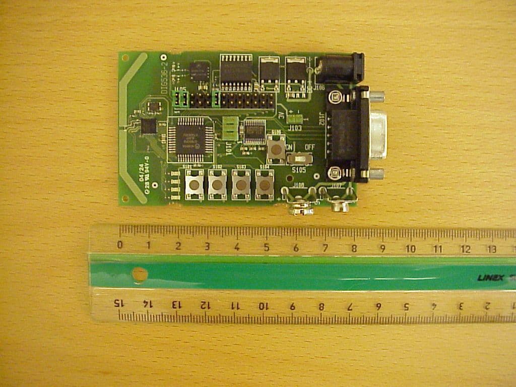
O2O13192-SARD
Aug 24, 2004IEEE 802.15.4 Transceiver
Equipment Class
DTS - Digital Transmission System
O2OBTDVK110
Jan 22, 2003Bluetooth Developer Kit
Equipment Class
DSS - Part 15 Spread Spectrum Transmitter
O2OBTP2M100
Jul 16, 2002Motorola Bluetooth Phone Module
Equipment Class
DSS - Part 15 Spread Spectrum Transmitter
O2OBTHCK100
Apr 23, 2002Bluetooth Hands Free Car Kit
Equipment Class
DSS - Part 15 Spread Spectrum Transmitter