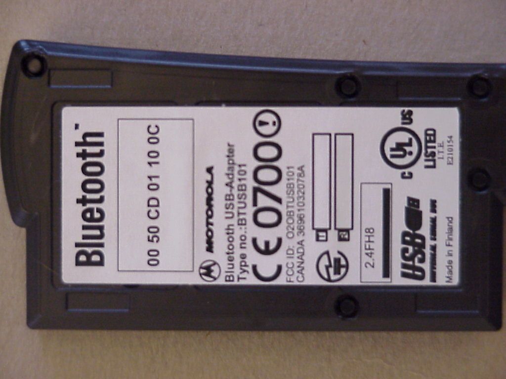
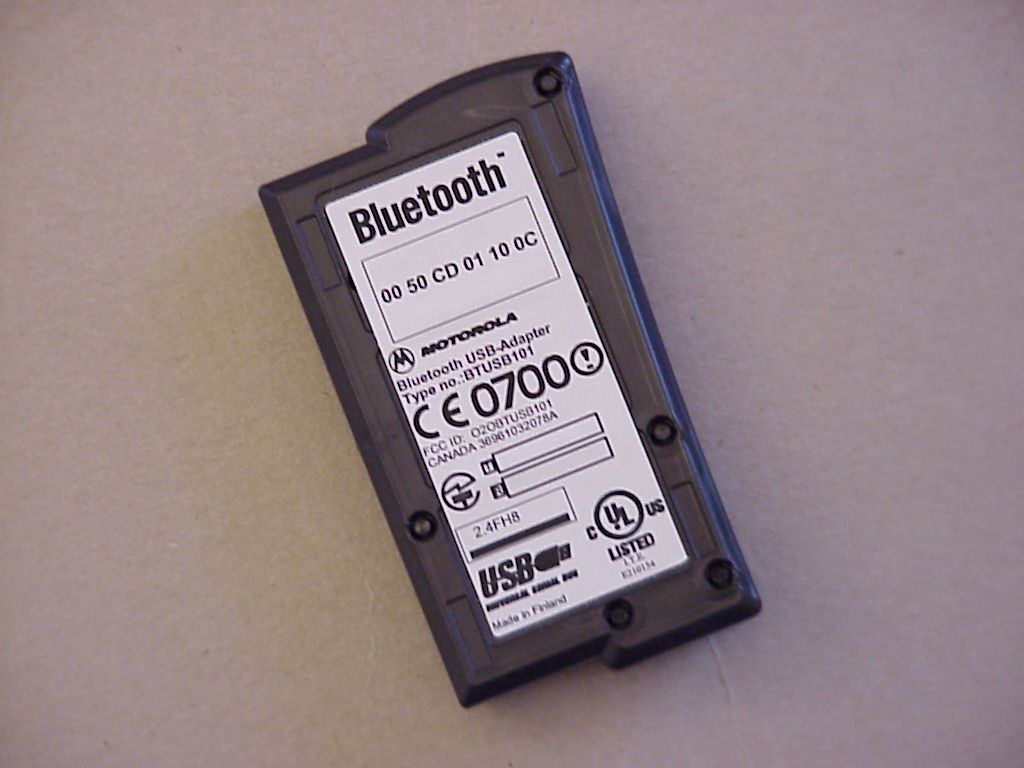
O2OBTUSB101USB Bluetooth Transmitter
Digianswer A/S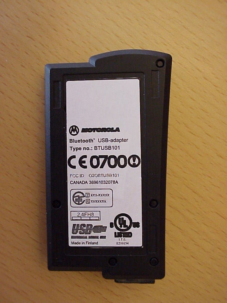
Click to zoom
Application Details
- Equipment Class
- DSS - Part 15 Spread Spectrum Transmitter
- Date of Grant
- Mar 28, 2001
- Application Purpose
- Original Equipment
- Date of Application
- Mar 28, 2001
- Equipment Note
- USB Bluetooth Transmitter
- Frequency Range
- 2401.00000000 - 2480.00000000
- Company
- Digianswer A/S
- Country
- Denmark
Documents & Files
Document Text
Text extracted from the exhibit documents filed with the FCC. Open a document above to read the original.
Users Manual
SOFTWARE SUITE USB ADAPTER INSTALLATION GUIDE Contents About this guide, 3 System requirements, 3 Connecting USB adapter, 4 Installing drivers, 4 Installing application software, 5 Uninstalling application software, 6 Operation, 6 Regulatory statements, 7 CAUTION FCC Radio-Frequency Exposure Statement This equipment generates and radiates radio-frequency energy. In order to comply with FCC radio-frequency radiation exposure guidelines for an uncontrolled environment, this equipment has to be installed and operated while maintaining a minimum body to antenna distance of 20 cm. Users are not permitted to make changes or modify the system in any way. 3 About this guide This Installation Guide will show you how to install the Bluetooth™ Software Suite v1.0. The instructions will cover: • Connecting the Bluetooth USB adapter and installing the drivers, i.e. software programs needed for the adapter to work. • Installing the application software. Furthermore, users who have a previous version of the Bluetooth Software Suite will find information on how to uninstall the old version before installing the new one. Additional documentation In addition to this Installation Guide, the Bluetooth Software Suite is accompanied by the following documents: A Beginner’s Guide providing a general introduction to the Bluetooth technology, and a User’s Manual covering all aspects of operating the Bluetooth Software Suite. You will find these documents on the Bluetooth Software Suite CD- ROM. Adobe Acrobat Reader The documents accompanying the Bluetooth Software Suite are provided in the PDF format. To view these documents, you will need Adobe Acrobat Reader. If that program is not already installed on your computer, you can install it from the CD-ROM: 1. Click Start. 2. Click Run. 3. Type D:\Acrobat\ar405eng.exe (substitute the appropriate letter of your CD-ROM drive for D). 4. Follow the onscreen prompts to complete the installation of Adobe Acrobat Reader. When Adobe Acrobat Reader has been installed on your computer, simply double-click a PDF document to open it. Disclaimer Any responsibility or liability for loss or damage in connection with the use of this product and the accompanying documentation is disclaimed. The information in this document is furnished for informational use only, is subject to change without notice, may contain errors or inaccuracies, and represents no commitment whatsoever. This agreement is governed by the laws of Denmark. Rev. TR 1.0 00-09-19 System Requirements The Bluetooth Software Suite can be installed on computers running the following operating systems: • Windows 98 • Windows Me • Windows 2000 4 Connecting USB adapter To install the Bluetooth Software Suite, first connect the USB adapter to your computer: 1. Turn on the computer. 2. Make sure all programs are closed. 3. Plug the USB adapter into an available USB port at the back of the computer. Back of PC USB USB adaptor Installing drivers The first time you connect the USB adapter to your computer, Windows will tell you that it needs to find drivers for the new hardware. A driver is a software program needed for a piece of hardware to work. 1. Insert the Bluetooth Software Suite CD-ROM. 2. Follow the onscreen prompts to complete the installation of drivers. Location of drivers When Windows asks you to specify the location of the drivers, type the following (substitute the appropriate letter of your CD-ROM drive for D): • Windows 98 and Me users: D:\drivers\win9x • Windows 2000 users: D:\drivers\w2k Found New Hardware Wizard During the installation, the Found New Hardware Wizard will appear a number of times. The following drivers are found: • Bluetooth USB Adapter. • Bluetooth Ethernet Adapter Note: On Windows 2000, if told Digital Signature Not Found and asked whether you want to continue, click Yes. In addition on Windows 2000 the following drivers are found: • Bluetooth RFCOMM Protocol. • Bluetooth SDP Protocol. Do not remove CD-ROM Do not remove the Bluetooth Software Suite CD-ROM from the computer until you have installed the application software. 5 Installing application software Note: If a previous version of the Bluetooth Software Suite is installed on your computer, this must be uninstalled before the installation of the new application software can take place. See the section Uninstalling application software. Having connected the USB adapter, inserted the CD-ROM, and installed the drivers, you are now ready to install the software for the Bluetooth Software Suite applications. To do so, follow the instructions in this section. (If Autorun is enabled on your computer, in some cases steps 1-3 may be skipped.) 1. Click Start. 2. Click Run. 3. Type D:\setup.exe (substitute the appropriate letter of your CD- ROM drive for D). 4. Follow the onscreen prompts to complete the installation of the application software. Adding new folders During the installation, the program will ask where to install the Bluetooth Software Suite files. A destination folder is suggested that should suit most users: C:\...\... Bluetooth Software Suite ... Alternatively, you can browse for any destination you prefer. Furthermore, the program will ask where to add the Bluetooth Software Suite icons. A program folder is suggested that should suit most users: C:\...\... Bluetooth Software Suite ... Alternatively, you can type a new folder name in Program Folders, or select one from Existing Folders. Creating network profiles During the installation, the Network Manager Wizard will create two network profiles on your system: one saving your current system network settings and one to be used for Bluetooth ad hoc networking. The program will guide you through this procedure. For more information on Bluetooth networking, please refer to the User's Manual. Restart now When the installation is complete, the program will ask if the computer should be restarted now or later. To be able to operate the Bluetooth Software Suite, restart the computer. 6 U…
Text truncated - open the document above for the full version.
Users Manual
SOFTWARE SUITE User’s Manual Bluetooth Software Suite User’s Manual 2 About this manual This User’s Manual will provide you with the information needed to make the most of the Bluetooth Software Suite. If you need basic information on the Bluetooth technology, please refer to the Beginner's Guide accompanying the Bluetooth Software Suite. Both the Beginner's Guide and this User's Manual are included on the Bluetooth Software Suite CD- ROM. Also, when you have installed the Bluetooth Software Suite, the two documents are available from the Windows Start menu. The Bluetooth Software Suite and Microsoft Windows are highly integrated. However, it is beyond the scope of this manual to explain the basics of using Windows. Therefore, if you need information on that topic, please refer to the Windows online help. The information in this document is furnished for informational use only, is subject to change without notice, may contain errors or inaccuracies, and represents no commitment whatsoever. Rev. TR 1.0 00-09-15 CAUTION FCC Radio-Frequency Exposure Statement This equipment generates and radiates radio- frequency energy. In order to comply with FCC radio-frequency radiation exposure guidelines for an uncontrolled environment, this equipment has to be installed and operated while maintaining a minimum body to antenna distance of 20 cm. Users are not permitted to make changes or modify the system in any way. Bluetooth Software Suite User’s Manual 3 Contents About this manual 2 CAUTION 2 Getting started 5 Bluetooth Neighborhood 5 Introduction 5 Opening Bluetooth Neighborhood 6 Bluetooth Neighborhood window 7 Profiles and services 8 List view 9 Basic functions 11 Naming your local device 11 Device discovery 12 Service discovery 13 Link establishment 14 Disconnecting 15 Status information 15 View details 16 Device folders 18 Online help 19 Local services 20 Object transfer 20 Making default business card available 20 Business card transfer 24 Sending objects directly from MS Outlook 25 Receiving objects 25 Creating objects in the Object Editor 26 File transfer 28 Audio 30 Bluetooth COM ports 32 General information 32 Bluetooth COM port settings 33 Bluetooth COM port link establishment 36 LAN 36 DUN 37 FAX 38 Network 39 Setting up networks 39 Network link establishment 40 Local device settings 40 Local profile properties 40 General information 40 Enabling/disabling profile 41 Object Push Settings 42 Object Push - Security 43 File Transfer Settings 44 Audio settings 45 Bluetooth Speaker Phone Setup Wizard 46 LAN Access settings 48 Dial-up Networking settings 49 Bluetooth Software Suite User’s Manual 4 Bluetooth Neighborhood properties 50 General 50 Settings 51 Device discovery 52 Trust 53 Security 55 Bonding 57 Bluetooth unit settings 59 Enabling/disabling Bluetooth unit 59 Indication of Bluetooth unit state 59 Remote device settings 60 Remote device properties 60 General 60 Trust 61 Hardware 63 LED operation 63 PC card technical specifications 63 USB adapter technical specifications 63 Diagnostics 64 Appendices 66 Appendix A: Profiles 66 Appendix B: List view icons 67 Appendix C: Regulatory statements 69 Index 71 Bluetooth Software Suite User’s Manual 5 Getting started Bluetooth Neighborhood Introduction With the Bluetooth™ Software Suite, you can establish wireless links between your computer and other Bluetooth enabled devices. Without using an inch of cable, you can for example: • Transfer sound, objects and files; • Access the Internet by means of dial-up networking; • Connect to local area networks; • Send fax messages, using the fax software of your computer; • Establish Bluetooth ad hoc networks consisting of two or more Bluetooth devices; • Connect to serial devices (legacy applications). Most operations are carried out from an application called the Bluetooth Neigborhood. The basic functions of the Bluetooth Neighborhood include three steps: 1. Carrying out device discovery, i.e. finding out which remote Bluetooth devices are available within your range; 2. Carrying out service discovery, i.e. finding out which services (applications) a remote device facilitates; 3. Establishing links to remote devices. The Bluetooth Neighborhood should be seen as an equivalent to the Network Neighborhood. The latter is an ordinary network, the Bluetooth Neighborhood is a wireless network of the Bluetooth devices within range. Bluetooth Software Suite User’s Manual 6 Opening Bluetooth Neighborhood The Bluetooth Neighborhood and Windows Explorer are highly integrated. Therefore, Windows Explorer is the natural place to open the Bluetooth Neighborhood: Open Windows Explorer, and select the Bluetooth Neighborhood among the folders in Windows. Alternatively, you can open the Bluetooth Neighborhood from the shortcut placed on your desktop during the installation: Bluetooth Software Suite User’s Manual 7 Bluetooth Neighborhood window When you open the Bluetooth Neighborhood, the following window appears * : The figures 1-7 refer to the following explanations: * The first time you open the Bluetooth Neighborhood, you will not see any remote Bluetooth devices. To discover the remote devices within range, press F5. For information on the contents of the list view, see the section “List view”. Note also that as the setup of the window depends on your Windows Explorer setup, the components in the above example may not be exactly the ones shown on your screen. 1: Menu bar: Contains standard Windows pull- down menus and a Bluetooth menu. We will deal with the Bluetooth menu in later sections. Furthermore, from the menu bar, you can access the Bluetooth Software Suite online help. 2: Tool bar: Contains standard Windows tools like Back, Forward, View, etc. In addition, the bar contains such Bluetooth tools as Device Discovery and Disconnect. 3: Address bar: Shows which item is currently selected. Also, from this bar you can browse in Windows Explorer. 4: View details: Appears when on the View menu you have selected the…
Text truncated - open the document above for the full version.
Operational Description
Written by: CS/HK Doc. version: 1.2 Page: 1 of 7 Project: Digianswer Bluetooth USB Adapter – DGABTUB101 Project no: 90 Date: 00-09-18 Subject: +20dBm Radio Block Diagram Description Block Diagram description of the +20 dBm Digianswer Bluetooth USB Adapter DGABTUB101 Written by: CS/HK Doc. version: 1.2 Page: 2 of 7 Project: Digianswer Bluetooth USB Adapter – DGABTUB101 Project no: 90 Date: 00-09-18 Subject: +20dBm Radio Block Diagram Description 1 Table of Contents 1 Table of Contents.................................................................................................................................2 2 Revision History....................................................................................................................................2 3 General................................................................................................................................................3 4 Radio Description..................................................................................................................................3 4.1 LMX3162 transceiver IC.................................................................................................................3 4.2 Transmit Operation........................................................................................................................3 4.3 Receiver Operation........................................................................................................................4 5 Bluetooth Base Band............................................................................................................................4 6 Memory................................................................................................................................................5 7 DSP.....................................................................................................................................................5 8 USB Controller......................................................................................................................................6 9 Power Supply.......................................................................................................................................6 9.1 General supply...............................................................................................................................6 9.2 Radio supply..................................................................................................................................6 10 USB Interface....................................................................................................................................6 11 +20dBm USB-Dongle Block Diagram..................................................................................................7 2 Revision History Revision Date Author Changes 1.1 03-07-00 CS Supply voltages added to the Block Diagram Written by: CS/HK Doc. version: 1.2 Page: 3 of 7 Project: Digianswer Bluetooth USB Adapter – DGABTUB101 Project no: 90 Date: 00-09-18 Subject: +20dBm Radio Block Diagram Description 3 General This document contains a Block description of the +20dBm USB module. The main focus is based on the radio module, which is more thoroughly described than the rest of the module. The chapters in this document refers to the respective blocks in the block diagram on the last page of the document. 4 Radio Description This section is a description of the +20dBm Digianswer Bluetooth generation 1 radio block diagram. The +20dBm radio is shown as the content inside the hatched block in the block diagram below. 4.1 LMX3162 transceiver IC The main block of the radio is the National Semiconductor LMX3162 radio transceiver, which in fact is an upbanded DECT transceiver. The LMX3162 radio transceiver consists of a phase locked loop PLL, transmit and receive functions. The 1,3GHz PLL is shared between the transmit and receive sections. The data is transmitted and received in different time slots. The time length is dependent upon the packet type transmitted and received. The PLL is able to hop to the desired carrier frequency in a given amount of time before data transmission and reception starts. The transmitter part of the LMX3162 includes a frequency doubler and it employs direct VCO modulation. The receiver part consists of a 2,5GHz low noise converting mixer, an intermediate frequency amplifier, a high gain limiting amplifier, a frequency discriminator, and a received signal-strength indicator (RSSI) circuit. The RSSI circuit is in this implementation used for channel quality monitoring and link regulation of transmitter power as required in the power class 1 Bluetooth standard. The receiver section has a simple heterodyne receiver, ie. single conversion architecture and the received signal is demodulated using a quadrature discriminator. The transceiver IC has on-chip regulators in order to allow supply ranges from 3.0VDC to 5.5VDC. The frequency reference to the transceiver IC is a divide by 4 version of the onboard 16MHz main clock. This main clock is fed to the radio controller (BTIC2/LMX5001), and internal divided by 4 and then fed as the PLL_OSC (4MHz reference) signal to the transceiver IC. The signals SER_CLK, SER_LE, SER_DATA, REC_CE, RX_PD, TX_PD and PLL_PD are transceiver control signals to and from BTIC2. 4.2 Transmit Operation A transmit RF signal is generated by very simple frequency modulation of the VCO. The VCO is seen external to the transceiver IC at the block diagram. The VCO is a none band-switching VCO, which in transmit mode varies in the frequency range of 1201-1247.5MHz dependent of the hopping scheme. It is done in open loop operation. The TX_DATA transmitted from the BTIC2 IC is Gaussian filtered using a discrete filter before entering the VCO. The amplitude of the signal generated by BTIC2 (TX_DATA) is adjusted by a resistive divider Written by: CS/HK Doc. version: 1.2 Page: 4 of 7 Proj…
Text truncated - open the document above for the full version.
Test Report
EMC Measurement/Technical Report 4_Digi_0300_BT_FCC_g on 7 Layers AG Borsigstr. 11 40880 Ratingen Germany Note: The following test results relate only to the devices specified in this document. This report shall not be reproduced in parts without the written approval of the testing laboratory. Motorola Bluetooth USB Dongle BTUSB101 Registergericht - registered in: Ratingen, HRB 3264 Aufsichtratsvorsitzende - Chairman of the Supervisory Board: Dr. Sabine Grobecker Vorstand - Board of Directors: Dr. Wolfgang Dahm Dr. Hans-Jürgen Meckelburg 7 layers AG, Borsigstrasse 11 40880 Ratingen, Germany Phone: +49 (0) 2102 749 0 Fax: +49 (0) 2102 749 350 http://www.7Layers.com Report Reference: Table of Contents 0. Summary 0.1 Technical Report Summary 0.2 Measurement Summary 1. Administrative Data 1.1 Testing Laboratory 1.2 Project Data 1.3 Applicant Data 1.4 Manufacturer Data 3. Testobject Data 3.1 General EUT Description 3.2 EUT Main Components 3.3 Ancillary Equipment 3.4 EUT Setups 3.5 Operating Modes 4. Measurement Results Conducted Emissions Occupied Bandwidth Output Power Spurious Emissions Conducted 5. Testequipment 6. Foto Report 7. Setup Drawings 2 2 3 5 5 5 5 5 7 7 8 8 8 9 10 11 13 16 18 31 33 35 36 Spurious Emissions Radiated20 2. Product Labeling 2.1 FCC ID Label 2.2 Location of Label on the EUT 6 6 6 Dwell Time Power Density Channel Separation Processing Gain 25 27 29 30 4.1 4.2 4.3 4.4 4.5 4.6 4.7 4.8 4.9 8. Annex measurement plot12 additional measurement plot1 additional report for processing gain5 Pages Pages Pages Page 2 of 58Testreport Reference: 4_Digi_0300_BT_FCC_g 0 Summary 0.1 Technical Report Summary Type of Authorization: Certification for an Intentional Radiator (Frequency Hopping Spread Spectrum) Applicable FCC Rules: Prepared in accordance with the requirements of FCC Rules and Regulations as listed in 47 CFR Ch.1 Parts 0 to 19 (10-1-98 Edition). The following subparts are applicable to the results in this test report. Part 2, Subpart J - Equipment Authorization Procedures, Certification Sections Part 15, Subpart C - Intentional Radiators § 15.201 Equipment authorization requirement § 15.203 Antenna requirements § 15.207 Conducted limits § 15.209 Radiated emission limits; general requirements § 15.247 Operation within the bands 902-928 MHz, 2400-2483,5 MHZ and 5725-5850 MHz Summary Test Results: The EUT complied with all the applicable FCC rules as listed above. Note: The tests were selected and performed with reference to the FCC Public Notice DA 00- 705, released March 30, 2000 Page 3 of 58Testreport Reference: 4_Digi_0300_BT_FCC_g 0.2 Measurement Summary § 15.207FCC Part 15, Subpart C ANSI C63.41992The measurement was performed according to Conducted Emissions (AC Power LinConducted Emissions (AC Power Lin OP-ModeOP-ModeSetupSetupPortPortFinal ResultFinal Result setup 2op-mode 2enclosurepassed § 15.247 (a) (1) (ii)FCC Part 15, Subpart C ANSI C63.41992The measurement was performed according to Occupied BandwidthOccupied Bandwidth OP-ModeOP-ModeSetupSetupPortPortFinal ResultFinal Result setup 1op-mode 1temporary antenna portpassed setup 1op-mode 2temporary antenna portpassed setup 1op-mode 3temporary antenna portpassed setup 1op-mode 4temporary antenna portpassed setup 1op-mode 5temporary antenna portpassed § 15.247 (b) (1)FCC Part 15, Subpart C FCC §15.3110-1-1998The measurement was performed according to Peak Power OutputPeak Power Output OP-ModeOP-ModeSetupSetupPortPortFinal ResultFinal Result setup 1op-mode 1temporary antenna portpassed setup 1op-mode 2temporary antenna portpassed setup 1op-mode 3temporary antenna portpassed § 15.247 (c)FCC Part 15, Subpart C FCC §15.3110-1-1998The measurement was performed according to Spurious RF Conducted EmissionsSpurious RF Conducted Emissions OP-ModeOP-ModeSetupSetupPortPortFinal ResultFinal Result setup 1op-mode 1temporary antenna portpassed setup 1op-mode 2temporary antenna portpassed setup 1op-mode 3temporary antenna portpassed § 15.247 (c), §15.35 (b), § 15.209FCC Part 15, Subpart C ANSI C63.41992The measurement was performed according to Spurious Radiated EmissionsSpurious Radiated Emissions OP-ModeOP-ModeSetupSetupPortPortFinal ResultFinal Result setup 2op-mode 1enclosurepassed setup 3op-mode 1enclosurepassed setup 2op-mode 2enclosurepassed setup 3op-mode 2enclosurepassed setup 2op-mode 3enclosurepassed setup 3op-mode 3enclosurepassed § 15.247(g)FCC Part 15, Subpart C Page 4 of 58Testreport Reference: 4_Digi_0300_BT_FCC_g FCC §15.3110-1-1998The measurement was performed according to Dwell TimeDwell Time OP-ModeOP-ModeSetupSetupPortPortFinal ResultFinal Result setup 1op-mode 4temporary antenna portpassed setup 1op-mode 5temporary antenna portpassed § 15.247 (g)FCC Part 15, Subpart C FCC §15.3110-1-1998The measurement was performed according to Power DensityPower Density OP-ModeOP-ModeSetupSetupPortPortFinal ResultFinal Result setup 1op-mode 4temporary antenna portpassed setup 1op-mode 5temporary antenna portpassed § 15.247 (a) (1)FCC Part 15, Subpart C FCC §15.3110-1-1998The measurement was performed according to Channel SeparationChannel Separation OP-ModeOP-ModeSetupSetupPortPortFinal ResultFinal Result setup 1op-mode 4temporary antenna portpassed § 15.247 (g)FCC Part 15, Subpart C FCC §15.3110-1-1998The measurement was performed according to Processing GainProcessing Gain OP-ModeOP-ModeSetupSetupPortPortFinal ResultFinal Result see annexsee annextemporary antenna portpassed Responsible for Accreditation Scope: Responsible for Test Report: Page 5 of 58Testreport Reference: 4_Digi_0300_BT_FCC_g 1. Administrative Data 1.1 Testing Laborato Company Name: Address: The test facility is also accredited by the following accreditation organisation: Responsible for Accreditation Scope: 7 Layers AG Borsigstr. 11 40880 Ratingen Germany DAR-Registration no. TTI-P-G 178/99-10 Dipl.-Ing Bernhard Retka Dipl.-Ing Arndt Stöcker This facility has been fully described in a report submitted to the FCC and accepted in a letter dated February 07…
Text truncated - open the document above for the full version.
Test Report
EMC Measurement/Technical Report 4_Digi_0300_BT_FCC_h on 7 Layers AG Borsigstr. 11 40880 Ratingen Germany Note: The following test results relate only to the devices specified in this document. This report shall not be reproduced in parts without the written approval of the testing laboratory. Motorola Bluetooth USB Dongle BTUSB101 Registergericht - registered in: Ratingen, HRB 3264 Aufsichtratsvorsitzende - Chairman of the Supervisory Board: Dr. Sabine Grobecker Vorstand - Board of Directors: Dr. Wolfgang Dahm Dr. Hans-Jürgen Meckelburg 7 layers AG, Borsigstrasse 11 40880 Ratingen, Germany Phone: +49 (0) 2102 749 0 Fax: +49 (0) 2102 749 350 http://www.7Layers.com Report Reference: Table of Contents 0. Summary 0.1 Technical Report Summary 0.2 Measurement Summary 1. Administrative Data 1.1 Testing Laboratory 1.2 Project Data 1.3 Applicant Data 1.4 Manufacturer Data 3. Testobject Data 3.1 General EUT Description 3.2 EUT Main Components 3.3 Ancillary Equipment 3.4 EUT Setups 3.5 Operating Modes 4. Measurement Results Conducted Emissions Occupied Bandwidth Output Power Spurious Emissions Conducted 5. Testequipment 6. Foto Report 7. Setup Drawings 2 2 3 5 5 5 5 5 7 7 8 8 8 9 10 10 -- -- -- 15 17 19 Spurious Emissions Radiated12 2. Product Labeling 2.1 FCC ID Label 2.2 Location of Label on the EUT 6 6 6 Dwell Time Power Density Channel Separation Processing Gain -- -- -- -- 4.1 -- -- -- 4.2 -- -- -- -- 8. Annex additional measurement plot1 Pages Page 2 of 19Testreport Reference: 4_Digi_0300_BT_FCC_h 0 Summary 0.1 Technical Report Summary Type of Authorization: Certification for an Unintentional Radiator (Class B digital device) Applicable FCC Rules: Prepared in accordance with the requirements of FCC Rules and Regulations as listed in 47 CFR Ch.1 Parts 0 to 19 (10-1-98 Edition). The following subparts are applicable to the results in this test report. Part 2, Subpart J - Equipment Authorization Procedures, Certification Sections Part 15, Subpart B - Unintentional Radiators § 15.101 Equipment authorization requirement § 15.107 Conducted limits § 15.109 Radiated emission limits Summary Test Results: The EUT complied with all the applicable FCC rules as listed above. Note: The tests were selected and performed with reference to the FCC Public Notice DA 00- 705, released March 30, 2000 Page 3 of 19Testreport Reference: 4_Digi_0300_BT_FCC_h 0.2 Measurement Summary §15.107FCC Part 15, Subpart B ANSI C63.41992The measurement was performed according to Conducted Emissions (AC Power LinConducted Emissions (AC Power Lin OP-ModeOP-ModeSetupSetupPortPortFinal ResultFinal Result setup 2op-mode 2enclosurepassed §15.31, §15.109 (b)FCC Part 15, Subpart B ANSI C63.41992The measurement was performed according to Spurious Radiated EmissionsSpurious Radiated Emissions OP-ModeOP-ModeSetupSetupPortPortFinal ResultFinal Result setup 3op-mode 1enclosurepassed Responsible for Accreditation Scope: Responsible for Test Report: Page 4 of 19Testreport Reference: 4_Digi_0300_BT_FCC_h 1. Administrative Data 1.1 Testing Laborato Company Name: Address: The test facility is also accredited by the following accreditation organisation: Responsible for Accreditation Scope: 7 Layers AG Borsigstr. 11 40880 Ratingen Germany DAR-Registration no. TTI-P-G 178/99-10 Dipl.-Ing Bernhard Retka Dipl.-Ing Arndt Stöcker This facility has been fully described in a report submitted to the FCC and accepted in a letter dated February 07, 2000 under the registration number 96716. - Deutscher Akkreditierungs Rat - Regulierungsbehörde für Telekommunikation und Post (Reg TP) 05.11.00 Arndt Stöcker 24.11.00 7.11.00 - 17.11.00 Project Leader: Receipt of EUT: Date of Test(s): Date of Report: 1.2 Project Data Digianswer A/S Tom Ringdtvet Skalhuse 5 DK-9240 Nibe Denmark see applicant 1.4 Manufacturer Data Company Name: Address: Contact Person: Company Name: Address: Contact Person: 1.3 Applicant Data Page 5 of 19Testreport Reference: 4_Digi_0300_BT_FCC_h 2.0 Product Labeling 2.1 FCC ID Label: At the time of this report there was no ID label available. This will be added to the report whenever the report will be sent to the FCC. 2.2 Location of Label on the EUT: Page 6 of 19Testreport Reference: 4_Digi_0300_BT_FCC_h 3. Testobject Data Type Designation: Kind of Device: (optional) Voltage Type: Voltage level: Equipment under Test: BTUSB101 Bluetooth device Motorola Bluetooth USB Dongle DC 5,0 V Ports 3.1 General EUT Descriptio General product description: Bluetooth is a short-range radio link intended to be a cable replacement between portable and/or fixed electronic devices. Bluetooth operates in the unlicensed ISM Band at 2.4 GHz. In the US a band of 83.5 MHz width is available. In this band, 79 RF channels spaced 1MHz apart a defined. The channel is represented by a pseudo-random hopping sequence through the 79 channels. The channel is devided into time slots, with a nominal slot length of 625μs, where each slot corresponds to different RF hop frequencies. The nominal hop rate is 1600 hops/s. All frequencies are equally used. The average time of occupancy is 0.3797 s within a 30 second period. The symbol rate on the channel is 1 Ms/s. The maximum output power, including antenna gain, is 23 dBm. The EUT provides the following ports: enlosure pcb antenna enlosure patch antenna temporary antenna port USB Port The main components of EUT are listed and described in Chapter 3.2 Page 7 of 19Testreport Reference: 4_Digi_0300_BT_FCC_h Short Description Equipment under Test Type Designation 3.2 EUT Main components: Type, S/N, Short Descriptions etc. used in this Test Report HW StatusSW StatusSerial No.Date of Receipt Dig 433-91.080050CD100A4305.11.00BTUSB101Bluetooth USB Adapter EUT A This EUT was equipped with a temporary antenna port Dig 433-91.080050CD100A4205.11.00BTUSB101Bluetooth USB Adapter EUT B This EUT is equipped witht two integral antennas. One patch antenna and one PCB antenna. The PCB antenna has a maximum gain of 2.52 dBi and the patch antenna has a …
Text truncated - open the document above for the full version.
Contact Information
Applicant
Jorgen Holst(Functional Manager, Platform & IT)
Technical Contact
Met LaboratoriesChris Harvey
[email protected]410-354-3300
914 West Patapasco Ave. · Baltimore, Maryland · United States
Test Firm
7layers AGRobert Machulec
Technical Specifications
| # | Rule Parts | Frequency Range | Power Output |
|---|---|---|---|
| 2 | 15C | 2.40 GHz - 2.48 GHz | 2.65 mW |
Other Applications from Digianswer A/S
O2O13192-EVB
Sep 21, 2004WPAN Transceiver
Equipment Class
DTS - Digital Transmission System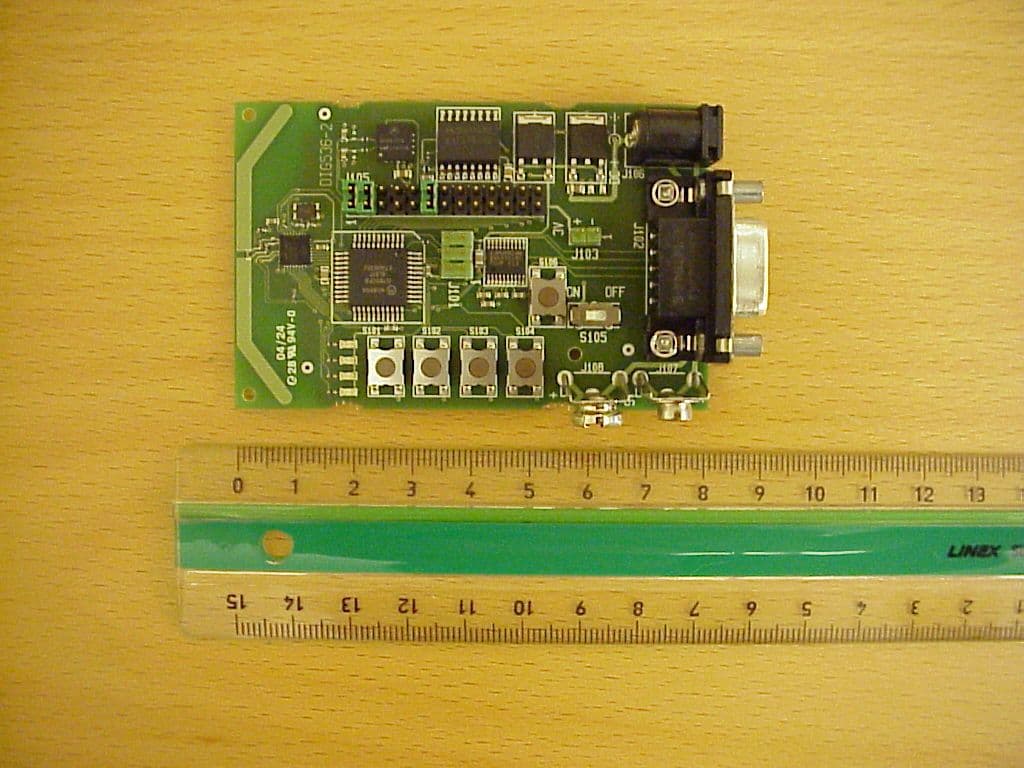
O2O13192-SARD
Aug 24, 2004IEEE 802.15.4 Transceiver
Equipment Class
DTS - Digital Transmission System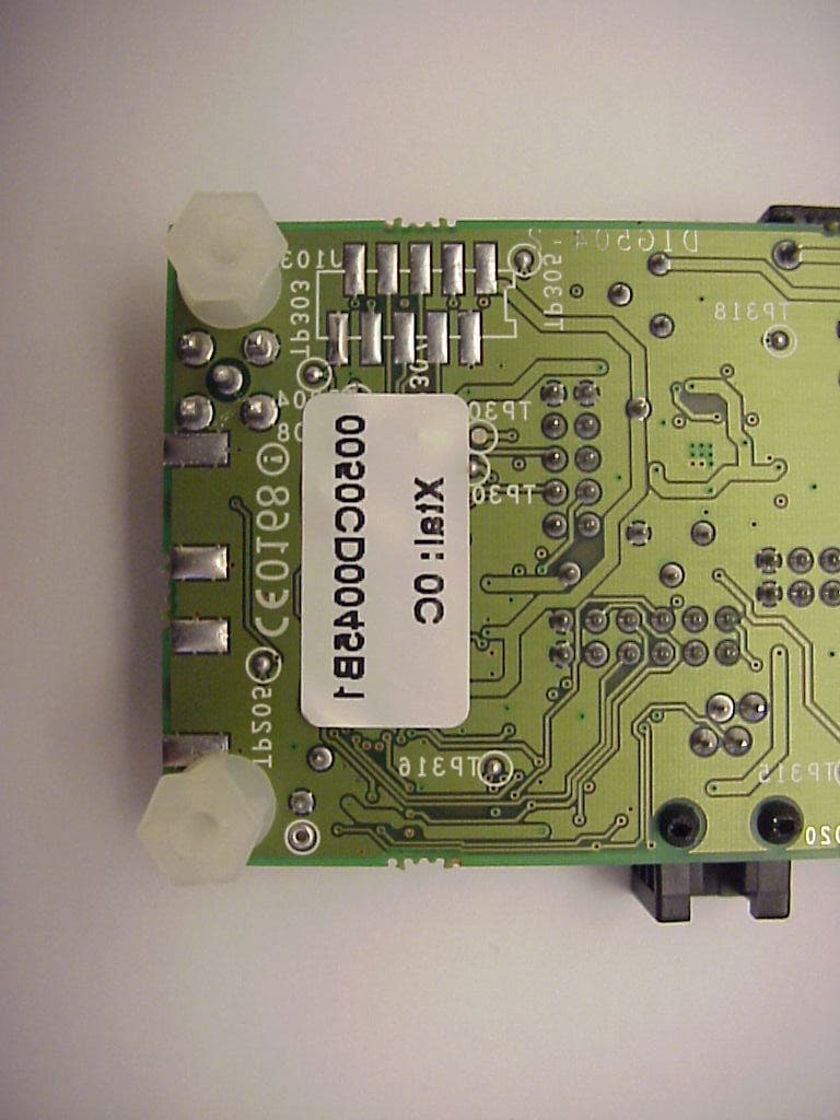
O2OBTDVK110
Jan 22, 2003Bluetooth Developer Kit
Equipment Class
DSS - Part 15 Spread Spectrum Transmitter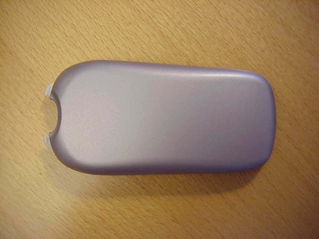
O2OBTP2M100
Jul 16, 2002Motorola Bluetooth Phone Module
Equipment Class
DSS - Part 15 Spread Spectrum Transmitter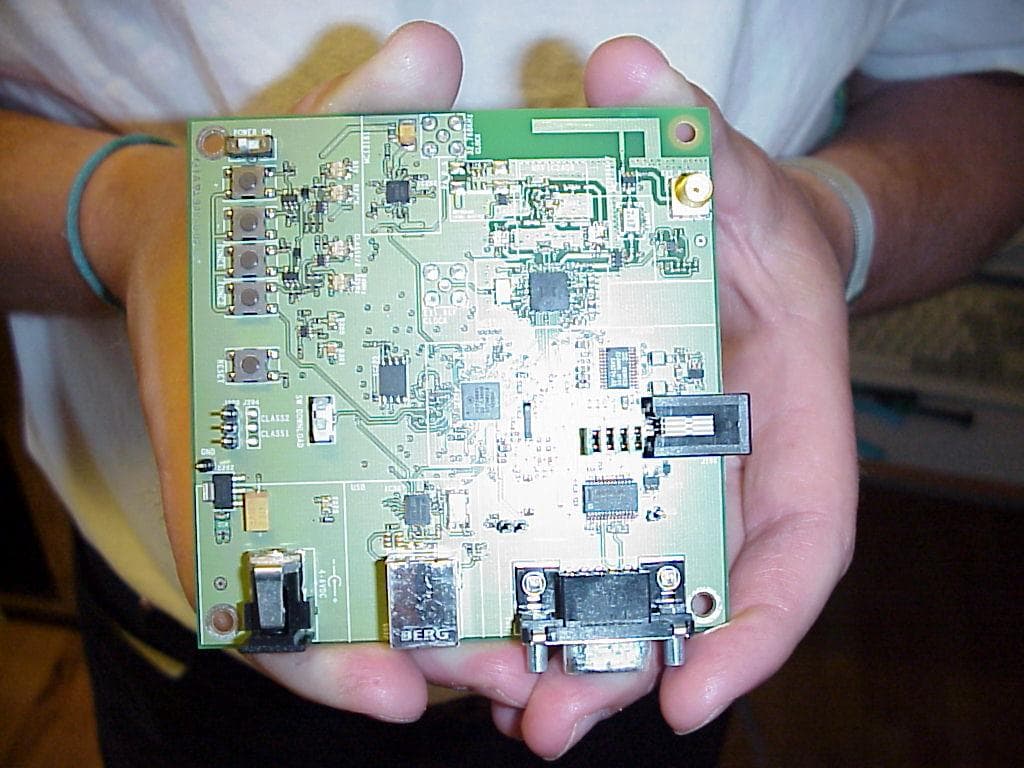
O2OBTDVK100
Jun 27, 2002Bluetooth Developer Kit
Equipment Class
JBP - Part 15 Class B Computing Device Peripheral