O2ODGABTPA101Bluetooth Protocol Analyzer
Digianswer A/S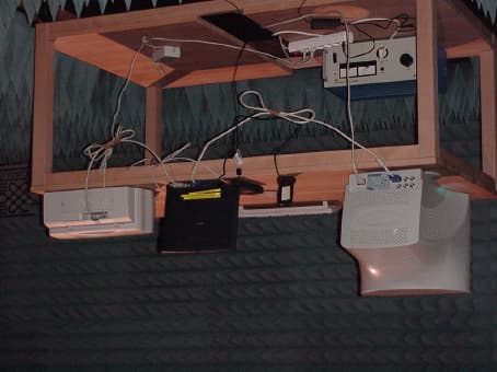
Click to zoom
Application Details
- Equipment Class
- DSS - Part 15 Spread Spectrum Transmitter
- Date of Grant
- Mar 01, 2001
- Application Purpose
- Original Equipment
- Date of Application
- Mar 01, 2001
- Equipment Note
- Bluetooth Protocol Analyzer
- Frequency Range
- 2401.00000000 - 2480.00000000
- Company
- Digianswer A/S
- Country
- Denmark
Documents & Files
Document Text
Text extracted from the exhibit documents filed with the FCC. Open a document above to read the original.
Users Manual
Bluetooth Protocol Analyser Digi answer A/S Installation & Operation Manual Digianswer Bluetooth Protocol Analyser Installation & Operation Manual C C o o n n t t e e n n t t s s CAUTION, 2 About this manual, 3 Unpacking, 3 Introduction, 4 Installation, 5 Installing hardware and drivers, 5 Installing application software, 6 Uninstalling old programs, 6 Data Collector operation, 8 Features, 8 Main window, 9 Starting log session, 10 Stopping log session, 12 Opening old log session, 12 Saving log session, 12 Exit, 13 Bluetooth Packet Analyser operation, 13 Features, 13 Main window, 14 Opening a file, 15 Filter setup, 15 View setup, 16 Hex view, 16 Back to Baseband, 17 One level up/down, 17 Exit, 17 Technical facts, 18 System requirements, 18 Upgrades, 18 Hardware specifications, 18 Bluetooth radio specifications, 18 Bluetooth Protocol Analyser packet format, 18 Appendices: A: Changes implemented since v1.0, 19 B: Packet format, 20 C: Regulatory statements, 22 D: Digianswer contact information, 23 Digianswer Bluetooth Protocol Analyser Installation & Operation Manual 2 C C A A U U T T I I O O N N FCC Radio-Frequency Exposure Statement This equipment generates and radiates radio-frequency energy. In order to comply with FCC radio-frequency radiation exposure guidelines for an uncontrolled environment, this equipment has to be installed and operated while maintaining a minimum body-to-antenna distance of 20 cm. Users are not permitted to make changes or modify the system in any way. Digianswer Bluetooth Protocol Analyser Installation & Operation Manual 3 A A b b o o u u t t t t h h i i s s m m a a n n u u a a l l This installation and operation manual provides you with the information you need to make maximum use of Digianswer’s Bluetooth™ Protocol Analyser. The manual is structured as follows: • The Introduction provides basic information on what the Bluetooth Protocol Analyser is and how it works. • The sections on Installation explain how to connect the USB-based hardware unit, install drivers, and install the software applications. Furthermore, this section contains information on necessary deinstallation of certain programs before the installation of the Bluetooth Protocol Analyser can take place. • The sections on Operation provide instructions in how to use the Data Collector and the Bluetooth Packet Analyser respectively. • Technical facts contains system requirements, upgrade information, and hardware specifications. • The Appendices provide a list of the changes implemented since the previous version of the product. Also, you will find information on the packet format of the Bluetooth Protocol Analyser, allowing developers to build alternatives to Digianswer's Bluetooth Packet Analyser module. Finally, the manual contains various regulatory statements, and information on how to get in contact with Digianswer. Note: This product has been designed for development purposes and is not to be sold to or used by end users. Legal disclaimer Any responsibility or liability for loss or damage in connection with the use of this product and the accompanying documentation is disclaimed. The information in this document is furnished for informational use only, is subject to change without notice, may contain errors or inaccuracies, and represents no commitment whatsoever. This agreement is governed by the laws of Denmark. Rev: 1.1 – 00-09-08 U U n n p p a a c c k k i i n n g g The Bluetooth Protocol Analyser package contains the following items: • Bluetooth USB Protocol Analyser • Cable for Bluetooth USB Protocol Analyser • Bluetooth Protocol Analyser CD-ROM • Installation & operation manual Digianswer Bluetooth Protocol Analyser Installation & Operation Manual 4 I I n n t t r r o o d d u u c c t t i i o o n n Digianswer’s Bluetooth Protocol Analyser is a development kit that allows you to view Bluetooth protocol data and carry out fast and effective analysis during the process of developing Bluetooth equipment. Basically, the Bluetooth Protocol Analyser consists of a USB- based hardware unit and a software application called the Data Collector. With this equipment you can set up a log session during which you can intercept all the data transmitted between devices forming a Bluetooth piconet. Accompanying the Bluetooth Protocol Analyser is a software application called the Bluetooth Packet Analyser, which is used for analysing the data logged during a session. The Bluetooth Packet Analyser can display all the baseband packets logged, and isolate, decode, and display LMP, L2CAP, RFCOMM, and SDP packets. The Bluetooth Packet Analyser works as a plug-in for the Data Collector module. This is an open interface, which means that anyone is free to develop alternative Analyser modules for the Bluetooth Protocol Analyser. The Bluetooth Protocol Analyser can be used in two configurations: •• As an independent unit: In this configuration, the Bluetooth Protocol Analyser does not participate in the piconet; it only listens in, logging all baseband packets transmitted between the master and slaves of the piconet. •• As a participant in the piconet: In this configuration, the Bluetooth Protocol Analyser is either the master or a slave of the piconet. The Bluetooth Protocol Analyser is attached to a computer running both the Data Collector application and Digianswer’s Bluetooth Software Suite * . The Data Collector logs all baseband packets transmitted from the computer to other participants of the piconet as well as the packets received by the computer. Note: While using the Bluetooth Protocol Analyser, it is advisable not to run any other applications on your computer – the Bluetooth Software Suite being an exception. * Digianswer’s Bluetooth Software Suite is automatically installed on your computer at the same time as the Bluetooth Protocol Analyser. Digianswer Bluetooth Protocol Analyser Installation & Operation Manual 5 I I n n s s t t a a l l l l a a t t i i o o n n The installation procedure includes in…
Text truncated - open the document above for the full version.
External Photos
Picture3testsetup rear view: Picture4Protokol Analyser DGABTPA101: Page 35 of 59Testreport Reference: 4_Digi_0300_BT_FCC_e
External Photos
Picture3testsetup rear view: Picture4Protokol Analyser DGABTPA101: Page 35 of 59Testreport Reference: 4_Digi_0300_BT_FCC_e
Operational Description
Written by: EMN Doc. version: 1.0 Page: 1 of 7 Project: Digianswer Bluetooth Protocol analyser Project no: 109 Date: 30-11-00 Subject: +20dBm Radio Block Diagram Description Block Diagram description of the +20 dBm Digianswer Bluetooth Protocol Analyser DGABTPA101 Written by: EMN Doc. version: 1.0 Page: 2 of 7 Project: Digianswer Bluetooth Protocol analyser Project no: 109 Date: 30-11-00 Subject: +20dBm Radio Block Diagram Description 1 Table of Contents 1 Table of Contents.......................................................................................................................................2 2 Revision History.........................................................................................................................................2 3 General......................................................................................................................................................3 4 Radio Description.......................................................................................................................................3 4.1 LMX3162 transceiver IC......................................................................................................................3 4.2 Transmit Operation.............................................................................................................................3 4.3 Receiver Operation.............................................................................................................................4 5 Bluetooth Base Band..................................................................................................................................4 6 Memory......................................................................................................................................................5 7 DSP...........................................................................................................................................................5 8 USB Controller...........................................................................................................................................6 9 Power Supply.............................................................................................................................................6 9.1 General supply....................................................................................................................................6 9.2 Radio supply.......................................................................................................................................6 10 USB Interface.........................................................................................................................................6 11 +20dBm Protocol Analyser Block Diagram..............................................................................................7 2 Revision History Revision Date Author Changes 1.0 30-11-00 EMN Born Written by: EMN Doc. version: 1.0 Page: 3 of 7 Project: Digianswer Bluetooth Protocol analyser Project no: 109 Date: 30-11-00 Subject: +20dBm Radio Block Diagram Description 3 General This document contains a Block description of the +20dBm Protocol Analyser. The main focus is based on the radio module, which is more thoroughly described than the rest of the module. The chapters in this document refers to the respective blocks in the block diagram on the last page of the document. 4 Radio Description This section is a description of the +20dBm Digianswer Bluetooth generation 1 radio block diagram. The +20dBm radio is shown as the content inside the hatched block in the block diagram below. 4.1 LMX3162 transceiver IC The main block of the radio is the National Semiconductor LMX3162 radio transceiver, which in fact is an upbanded DECT transceiver. The LMX3162 radio transceiver consists of a phase locked loop PLL, transmit and receive functions. The 1,3GHz PLL is shared between the transmit and receive sections. The data is transmitted and received in different time slots. The time length is dependent upon the packet type transmitted and received. The PLL is able to hop to the desired carrier frequency in a given amount of time before data transmission and reception starts. The transmitter part of the LMX3162 includes a frequency doubler and it employs direct VCO modulation. The receiver part consists of a 2,5GHz low noise converting mixer, an intermediate frequency amplifier, a high gain limiting amplifier, a frequency discriminator, and a received signal-strength indicator (RSSI) circuit. The RSSI circuit is in this implementation used for channel quality monitoring and link regulation of transmitter power as required in the power class 1 Bluetooth standard. The receiver section has a simple heterodyne receiver, ie. single conversion architecture and the received signal is demodulated using a quadrature discriminator. The transceiver IC has on-chip regulators in order to allow supply ranges from 3.0VDC to 5.5VDC. The frequency reference to the transceiver IC is a divide by 4 version of the onboard 16MHz main clock. This main clock is fed to the radio controller (BTIC2/LMX5001), and internal divided by 4 and then fed as the PLL_OSC (4MHz reference) signal to the transceiver IC. The signals SER_CLK, SER_LE, SER_DATA, REC_CE, RX_PD, TX_PD and PLL_PD are transceiver control signals to and from BTIC2. 4.2 Transmit Operation A transmit RF signal is generated by very simple frequency modulation of the VCO. The VCO is seen external to the transceiver IC at the block diagram. The VCO is a none band-switching VCO, which in transmit mode varies in the frequency range of 1201-1247.5MHz dependent of the hopping scheme. It is done in open loop operation. The TX_DATA transmitted from the BTIC2 IC is Gaussian filtered using a discrete filter before entering the VCO. The amplitude of the signal generated by BTIC2 (TX_DATA) is adjusted by a resistive divider Written by: EMN D…
Text truncated - open the document above for the full version.
Test Report
Summary of test results for Digianswer Protocol Analyser Traffic Mode Reference: FCC 15.249 (15.35b, 15.209) Use of patch antenna Frequency RangeOperating mode TX on Antenna Polarisation Diagram NameResult Passed (P) Failed (F) 30 MHz – 1 GHz2402 MHzH+VDigi_Pro_07P 30 MHz – 1 GHz2441 MHzH+VDigi_Pro_08P 30 MHz – 1 GHz2480 MHzH+VDigi_Pro_09P 1 – 18 GHz 2402 MHzH+VDigi_Pro_04P 1 – 18 GHz 2441 MHzH+VDigi_Pro_05P 1 – 18 GHz 2480 MHzH+VDigi_Pro_06P 18 – 25 GHz 2402 MHzH+VDigi_Pro_14P Use of pcb antenna Frequency RangeOperating mode TX on Antenna Polarisation Diagram No. + no. of pages Result Passed (P) Failed (F) 30 MHz – 1 GHz 2402 MHzH+VDigi_Pro_10P 30 MHz – 1 GHz 2441 MHzH+VDigi_Pro_11P 30 MHz – 1 GHz 2480 MHzH+VDigi_Pro_12P 1 – 18 GHz2402 MHzH+VDigi_Pro_02P 1 – 18 GHz2441 MHzH+VDigi_Pro_01P 1 – 18 GHz2480 MHzH+VDigi_Pro_03P SPURIOUS EMISSION RADIATED Diag.: 1 EUT:Protocol Analyser / 05.02.2001 Manufacturer:Digianswer A.S. Operating Condition:TX on 2441 MHz, Ant.01 Test Site:7 layers Ratingen Operator:Peu / Sto Test Specification:FCC 15.249 (15.35b, 15.209) Comment:vertical + horizontal Polarisation Start of Test:05.02.01 / 12:32:16 0 20 40 60 80 100 Level [dBμV/m] 1G2G3G4G5G6G7G8G9G10G18G Frequency [Hz] Marker: 2.441 GHz 79.51 dBμV/m MES Digi_Pro_01_pre PK MES Digi_Pro_01_pre AV LIM FCC 15.209 3m Field Strength QP/AV Limit LIM FCC 15.209 3m Peak Field Strength Peak Limit Page 1/1 07.02.01 18:59 Digi_Pro_01 SPURIOUS EMISSION RADIATED Diag.: 2 EUT:Protocol Analyser / 05.02.2001 Manufacturer:Digianswer A.S. Operating Condition:TX on 2402 MHz Ant.01 Test Site:7 layers Ratingen Operator:Peu / Sto Test Specification:FCC 15.249 (15.35b, 15.209) Comment:vertical + horizontal Polarisation Start of Test:05.02.01 / 13:20:45 10 20 30 40 50 60 70 80 90 100 Level [dBμV/m] 1G2G3G4G5G6G7G8G9G10G18G Frequency [Hz] Marker: 2.402 GHz 78.01 dBμV/m MES Digi_Pro_02_pre PK MES Digi_Pro_02_pre AV LIM FCC 15.209 3m Field Strength QP/AV Limit LIM FCC 15.209 3m Peak Field Strength Peak Limit Page 1/1 07.02.01 18:59 Digi_Pro_02 SPURIOUS EMISSION RADIATED Diag. 3 EUT:Protocol Analyser / 05.02.2001 Manufacturer:Digianswer A.S. Operating Condition:TX on 2480 MHz Ant.01 Test Site:7 layers Ratingen Operator:Peu / Sto Test Specification:FCC 15.249 (15.35b, 15.209) Comment:vertical + horizontal Polarisation Start of Test:05.02.01 / 14:27:53 0 10 20 30 40 50 60 70 80 90 Level [dBμV/m] 1G2G3G4G5G6G7G8G9G10G18G Frequency [Hz] Marker: 2.48 GHz 82.07 dBμV/m MES Digi_Pro_03_pre PK MES Digi_Pro_03_pre AV LIM FCC 15.209 3m Field Strength QP/AV Limit LIM FCC 15.209 3m Peak Field Strength Peak Limit Page 1/1 07.02.01 19:00 Digi_Pro_03 SPURIOUS EMISSION RADIATED Diag. 4 EUT:Protocol Analyser / 05.02.2001 Manufacturer:Digianswer A.S. Operating Condition:TX on 2402 MHz ; Ant.00 Test Site:7 layers Ratingen Operator:Mac/Sto Test Specification:FCC 15.249 (15.35b, 15.209) Comment:vertical + horizontal Polarisation Start of Test:05.02.01 / 14:48:45 0 10 20 30 40 50 60 70 80 90 Level [dBμV/m] 1G2G3G4G5G6G7G8G9G10G18G Frequency [Hz] Marker: 2.402 GHz 82.52 dBμV/m MES Digi_Pro_04_pre PK MES Digi_Pro_04_pre AV LIM FCC 15.209 3m Field Strength QP/AV Limit LIM FCC 15.209 3m Peak Field Strength Peak Limit Page 1/1 07.02.01 18:58 Digi_Pro_04 SPURIOUS EMISSION RADIATED Diag. 5 EUT:Protocol Analyser / 05.02.2001 Manufacturer:Digianswer A.S. Operating Condition:TX on 2441 MHz ; Ant.00 Test Site:7 layers Ratingen Operator:Mac/Sto Test Specification:FCC 15.249 (15.35b, 15.209) Comment:vertical + horizontal Polarisation Start of Test:05.02.01 / 15:29:32 0 10 20 30 40 50 60 70 80 90 Level [dBμV/m] 1G2G3G4G5G6G7G8G9G10G18G Frequency [Hz] Marker: 2.441 GHz 81.17 dBμV/m MES Digi_Pro_05_pre PK MES Digi_Pro_05_pre AV LIM FCC 15.209 3m Field Strength QP/AV Limit LIM FCC 15.209 3m Peak Field Strength Peak Limit Page 1/1 07.02.01 19:00 Digi_Pro_05 SPURIOUS EMISSION RADIATED Diag. 6 EUT:Protocol Analyser / 05.02.2001 Manufacturer:Digianswer A.S. Operating Condition:TX on 2480 MHz ; Ant.00 Test Site:7 layers Ratingen Operator:Mac/Sto Test Specification:FCC 15.249 (15.35b, 15.209) Comment:vertical + horizontal Polarisation Start of Test:05.02.01 / 15:59:07 0 10 20 30 40 50 60 70 80 90 Level [dBμV/m] 1G2G3G4G5G6G7G8G9G10G18G Frequency [Hz] Marker: 2.48 GHz 81.76 dBμV/m MES Digi_Pro_06_pre PK MES Digi_Pro_06_pre AV LIM FCC 15.209 3m Field Strength QP/AV Limit LIM FCC 15.209 3m Peak Field Strength Peak Limit Page 1/1 07.02.01 19:01 Digi_Pro_06 SPURIOUS EMISSION RADIATED Diag.: 7 EUT:Protocol Analyser / 05.02.2001 Manufacturer:Digianswer Operating Condition:Tx on 2402 MHz , Ant 00 Test Site:7 layers, Ratingen Operator:Mac/Sto Test Specification:FCC 15.247 (15.35b, 15.209) Comment:vertical + horizontal polarisation Start of Test:05.02.01 / 20:25:02 SCAN TABLE: "FCC 15.249 Field <1G" Short Description:EN 55022 Field Strength StartStopStepDetectorMeas.IFTransducer FrequencyFrequencyWidthTimeBandw. 30.0 MHz1.0 GHz60.0 kHzMaxPeak100.0 μs120 kHzHL562 0 10 20 30 40 50 60 70 80 Level [dBμV/m] 30M40M50M60M70M80M100M200M300M400M500M600M800M1G Frequency [Hz] xx x x x x x x x x x xMES Digi_Pro_07_fin QP MES Digi_Pro_07_pre PK LIM FCC 15.209 3m Field Strength QP/AV Limit Page 1/2 07.02.01 19:02 Digi_Pro_07 MEASUREMENT RESULT: "Digi_Pro_07_fin QP" 05.02.01 21:18 Frequency LevelTransd LimitMarginHeightAzimuthPolarisation MHz dBμV/m dBdBμV/m dB cm deg 240.000000 38.80 10.6 46.0 7.2 100.0 -71.00VERTICAL 331.800000 38.70 13.6 46.0 7.3 100.0 -58.00VERTICAL 464.040000 34.30 17.3 46.0 11.7 100.0 -94.00HORIZONTAL 596.460000 33.10 20.0 46.0 12.9 100.0 179.00VERTICAL 663.420000 32.20 21.1 46.0 13.8 125.0 162.00VERTICAL 730.440000 32.70 22.1 46.0 13.3 100.0 180.00VERTICAL Page 2/2 07.02.01 19:02 Digi_Pro_07 SPURIOUS EMISSION RADIATED Diag.: 8 EUT:Protocol Analyser / 05.02.2001 Manufacturer:Digianswer Operating Condition:Tx on 2441 MHz , Ant 00 Test Site:7 layers, Ratingen Operator:Mac/Sto Test Specification:FCC 15.247 (15.35b, 15.209) Comment:vertical + horizontal polarisation Start of Test:05.0…
Text truncated - open the document above for the full version.
Test Report
EMC Measurement/Technical Report 4_Digi_0300_BT_FCC_e on 7 Layers AG Borsigstr. 11 40880 Ratingen Germany Note: The following test results relate only to the devices specified in this document. This report shall not be reproduced in parts without the written approval of the testing laboratory. Bluetooth Protocol Analyser DGABTPA101 Registergericht - registered in: Ratingen, HRB 3264 Aufsichtratsvorsitzende - Chairman of the Supervisory Board: Dr. Sabine Grobecker Vorstand - Board of Directors: Dr. Wolfgang Dahm Dr. Hans-Jürgen Meckelburg 7 layers AG, Borsigstrasse 11 40880 Ratingen, Germany Phone: +49 (0) 2102 749 0 Fax: +49 (0) 2102 749 350 http://www.7Layers.com Report Reference: Table of Contents 0. Summary 0.1 Technical Report Summary 0.2 Measurement Summary 1. Administrative Data 1.1 Testing Laboratory 1.2 Project Data 1.3 Applicant Data 1.4 Manufacturer Data 3. Testobject Data 3.1 General EUT Description 3.2 EUT Main Components 3.3 Ancillary Equipment 3.4 EUT Setups 3.5 Operating Modes 4. Measurement Results Conducted Emissions Occupied Bandwidth Output Power Spurious Emissions Conducted 5. Testequipment 6. Foto Report 7. Setup Drawings 8. Annex 2 3 4 6 6 6 6 6 8 9 9 9 9 10 11 11 13 16 18 32 34 36 37 Measurement plots Spurious Emissions Radiated 20 2. Product Labeling 2.1 FCC ID Label 2.2 Location of Label on the EUT 7 7 7 Dwell Time Power Density Channel Separation Processing Gain 26 28 30 31 4.1 4.2 4.3 4.4 4.5 4.6 4.7 4.8 4.9 Page 2 of 59 Testreport Reference: 4_Digi_0300_BT_FCC_e 0 Summary 0.1 Technical Report Summary Type of Authorization Certification for an Intentional Radiator (Frequency Hopping Spread Spectrum) Applicable FCC Rules: Prepared in accordance with the requirements of FCC Rules and Regulations as listed in 47 CFR Ch.1 Parts 0 to 19 (10-1-98 Edition). The following subparts are applicable to the results in this test report. Part 2, Subpart J - Equipment Authorization Procedures, Certification Sections Part 15, Subpart C - Intentional Radiators § 15.201 Equipment authorization requirement § 15.203 Antenna requirements § 15.207 Conducted limits § 15.209 Radiated emission limits; general requirements § 15.247 Operation within the bands 902-928 MHz, 2400-2483,5 MHZ and 5725-5850 MHz Summary Test Results: The EUT complied with all the applicable FCC rules as listed above. Note: The tests were selected and performed with reference to the FCC Public Notice DA 00- 705, released March 30, 2000 Page 3 of 59 Testreport Reference: 4_Digi_0300_BT_FCC_e 0.2 Measurement Summary § 15.207FCC Part 15, Subpart C ANSI C63.41992 The measurement was performed according to Conducted Emissions (AC Power Line)Conducted Emissions (AC Power Line) OP-ModeOP-ModeSetupSetupPortPortFinal ResultFinal Result setup 2op-mode 2AC mains of connected lappassed § 15.247 (a) (1) (ii)FCC Part 15, Subpart C ANSI C63.41992 The measurement was performed according to Occupied BandwidthOccupied Bandwidth OP-ModeOP-ModeSetupSetupPortPortFinal ResultFinal Result setup 1op-mode 1 temporary antenna portpassed setup 1op-mode 2 temporary antenna portpassed setup 1op-mode 3 temporary antenna portpassed setup 1op-mode 4 temporary antenna portpassed setup 1op-mode 5 temporary antenna portpassed § 15.247 (b) (1)FCC Part 15, Subpart C FCC §15.3110-1-1998 The measurement was performed according to Peak Power OutputPeak Power Output OP-ModeOP-ModeSetupSetupPortPortFinal ResultFinal Result setup 1op-mode 1 temporary antenna portpassed setup 1op-mode 2 temporary antenna portpassed setup 1op-mode 3 temporary antenna portpassed § 15.247 (c)FCC Part 15, Subpart C FCC §15.3110-1-1998 The measurement was performed according to Spurious RF Conducted EmissionsSpurious RF Conducted Emissions OP-ModeOP-ModeSetupSetupPortPortFinal ResultFinal Result setup 1op-mode 1enclosurepassed setup 1op-mode 2enclosurepassed setup 1op-mode 3enclosurepassed § 15.247 (c), §15.35 (b), § 15.209FCC Part 15, Subpart C ANSI C63.41992 The measurement was performed according to Spurious Radiated EmissionsSpurious Radiated Emissions OP-ModeOP-ModeSetupSetupPortPortFinal ResultFinal Result setup 3op-mode 1enclosure pcb antennapassed setup 2op-mode 1enclosure patch antennapassed setup 2op-mode 2enclosure patch antennapassed setup 3op-mode 2enclosure pcb antennapassed setup 3op-mode 3enclosure pcb antennapassed setup 2op-mode 3enclosure patch antennapassed § 15.247(g)FCC Part 15, Subpart C Page 4 of 59 Testreport Reference: 4_Digi_0300_BT_FCC_e FCC §15.3110-1-1998 The measurement was performed according to Dwell TimeDwell Time OP-ModeOP-ModeSetupSetupPortPortFinal ResultFinal Result setup 1op-mode 4 temporary antenna portpassed setup 1op-mode 5 temporary antenna portpassed § 15.247 (g)FCC Part 15, Subpart C FCC §15.3110-1-1998 The measurement was performed according to Power DensityPower Density OP-ModeOP-ModeSetupSetupPortPortFinal ResultFinal Result setup 1op-mode 4 temporary antenna portpassed setup 1op-mode 5 temporary antenna portpassed § 15.247 (a) (1)FCC Part 15, Subpart C FCC §15.3110-1-1998 The measurement was performed according to Channel SeparationChannel Separation OP-ModeOP-ModeSetupSetupPortPortFinal ResultFinal Result setup 1op-mode 4 temporary antenna portpassed § 15.247 (g)FCC Part 15, Subpart C FCC §15.3110-1-1998 The measurement was performed according to Processing GainProcessing Gain OP-ModeOP-ModeSetupSetupPortPortFinal ResultFinal Result see add. Reportsee add. Reportsee add. Report Responsible for Accreditation Scope: Responsible for Test Report: Page 5 of 59Testreport Reference: 4_Digi_0300_BT_FCC_e 1. Administrative Data 1.1 Testing Laboratory Company Name: Address: The test facility is also accredited by the following accreditation organisation: Responsible for Accreditation Scope: 7 Layers AG Borsigstr. 11 40880 Ratingen Germany DAR-Registration no. TTI-P-G 178/99-10 Dipl.-Ing Bernhard Retka Dipl.-Ing Arndt Stöcker This facility has been fully described in a report submitted to the FCC and accepted in a letter dated February 07,…
Text truncated - open the document above for the full version.
Test Report
EMC Measurement/Technical Report 4_Digi_0300_BT_FCC_f on 7 Layers AG Borsigstr. 11 40880 Ratingen Germany Note: The following test results relate only to the devices specified in this document. This report shall not be reproduced in parts without the written approval of the testing laboratory. Bluetooth Protocol Analyser DGABTPA101 Registergericht - registered in: Ratingen, HRB 3264 Aufsichtratsvorsitzende - Chairman of the Supervisory Board: Dr. Sabine Grobecker Vorstand - Board of Directors: Dr. Wolfgang Dahm Dr. Hans-Jürgen Meckelburg 7 layers AG, Borsigstrasse 11 40880 Ratingen, Germany Phone: +49 (0) 2102 749 0 Fax: +49 (0) 2102 749 350 http://www.7Layers.com Report Reference: Table of Contents 0. Summary 0.1 Technical Report Summary 0.2 Measurement Summary 1. Administrative Data 1.1 Testing Laboratory 1.2 Project Data 1.3 Applicant Data 1.4 Manufacturer Data 3. Testobject Data 3.1 General EUT Description 3.2 EUT Main Components 3.3 Ancillary Equipment 3.4 EUT Setups 3.5 Operating Modes 4. Measurement Results Conducted Emissions Occupied Bandwidth Output Power Spurious Emissions Conducted 5. Testequipment 6. Foto Report 7. Setup Drawings 8. Annex 2 3 4 5 5 5 5 5 7 8 8 8 8 9 10 10 -- -- -- 15 17 18 19 Measurement plots Spurious Emissions Radiated 12 2. Product Labeling 2.1 FCC ID Label 2.2 Location of Label on the EUT 6 6 6 Dwell Time Power Density Channel Separation Processing Gain -- -- -- -- 4.1 -- -- -- 4.2 -- -- -- -- Page 2 of 19 Testreport Reference: 4_Digi_0300_BT_FCC_f 0 Summary 0.1 Technical Report Summary Type of Authorization Certification for an Unintentional Radiator (Class B digital device) Applicable FCC Rules: Prepared in accordance with the requirements of FCC Rules and Regulations as listed in 47 CFR Ch.1 Parts 0 to 19 (10-1-98 Edition). The following subparts are applicable to the results in this test report. Part 2, Subpart J - Equipment Authorization Procedures, Certification Sections Part 15, Subpart B - Unintentional Radiators § 15.101 Equipment authorization requirement § 15.107 Conducted limits § 15.109 Radiated emission limits Summary Test Results: The EUT complied with all the applicable FCC rules as listed above. Note: The tests were selected and performed with reference to the FCC Public Notice DA 00- 705, released March 30, 2000 Page 3 of 19 Testreport Reference: 4_Digi_0300_BT_FCC_f 0.2 Measurement Summary §15.107FCC Part 15, Subpart B ANSI C63.41992 The measurement was performed according to Conducted Emissions (AC Power Line)Conducted Emissions (AC Power Line) OP-ModeOP-ModeSetupSetupPortPortFinal ResultFinal Result setup 2op-mode 2AC mains of connected lappassed §15.31, §15.109FCC Part 15, Subpart B ANSI C63.41992 The measurement was performed according to Spurious Radiated EmissionsSpurious Radiated Emissions OP-ModeOP-ModeSetupSetupPortPortFinal ResultFinal Result setup 3op-mode 2enclosure pcb antennapassed Responsible for Accreditation Scope: Responsible for Test Report: Page 4 of 19Testreport Reference: 4_Digi_0300_BT_FCC_f 1. Administrative Data 1.1 Testing Laboratory Company Name: Address: The test facility is also accredited by the following accreditation organisation: Responsible for Accreditation Scope: 7 Layers AG Borsigstr. 11 40880 Ratingen Germany DAR-Registration no. TTI-P-G 178/99-10 Dipl.-Ing Bernhard Retka Dipl.-Ing Arndt Stöcker This facility has been fully described in a report submitted to the FCC and accepted in a letter dated February 07, 2000 under the registration number 96716. - Deutscher Akkreditierungs Rat - Regulierungsbehörde für Telekommunikation und Post (Reg TP) 31.10.00 Arndt Stöcker 21.11.00 31.10.00-21.11.00 1 Project Leader: Receipt of EUT: Date of Test(s): Date of Report: No. of Pages in Annex: 1.2 Project Data Digianswer A/S Skalhuse 5 DK-9240 Nibe Denmark see applicant 1.4 Manufacturer Data Company Name: Address: Contact Person: Company Name: Address: Contact Person: 1.3 Applicant Data Page 5 of 19 Testreport Reference: 4_Digi_0300_BT_FCC_f 2.0 Product Labeling 2.1 FCC ID Label: At the time of this report there was no ID label available. This will be added to the report whenever the report will be sent to the FCC. 2.2 Location of Label on the EUT: Page 6 of 19Testreport Reference: 4_Digi_0300_BT_FCC_f 3. Testobject Data Type Designation: Kind of Device: (optional) Voltage Type: Voltage level: Equipment under Test: DGABTPA101 Bluetooth device Bluetooth Protocol Analyser DC 5 V DC Ports 3.1 General EUT Description General product description: The EUT provides the following ports: AC mains of connected laptop temporary antenna port enclosure pcb antenna enclosure patch antenna The main components of EUT are listed and described in Chapter 3.2 Page 7 of 19 Testreport Reference: 4_Digi_0300_BT_FCC_f Short Description Equipment under Test Type Designation 3.2 EUT Main components: Type, S/N, Short Descriptions etc. used in this Test Report HW StatusSW StatusSerial No.Date of Receipt DIG433-91.080050CD01004F31.11.00DGABTPA101Protocol AnalyserEUT A For all conducted measurements DIG433-91.080050CD01004831.11.00 DGABTPA101Protocol AnalyserEUT B For all radiated measurements NOTE: The short description is used to simplify the identification of the EUT in this test report 3.3 Ancillary Equipment Short Description Equipment under Test Type DesignationHW StatusSW StatusSerial No.FCC Id For the purposes of this test report, ancillary equipment is defined as equipment which is used in conjunction with the EUT to provide additional operational and control features to the EUT. It is necessary to configure the system in a typical fashion, as a customer would normally use it. AE 6LaptopIBM 2609-21G--BA-69672409TA1- 25871-M5-E AE 5MonitorSamsung Sync Master 700p plus --SE17H3MK3052 94J CSE 78…
Text truncated - open the document above for the full version.
Contact Information
Applicant
Jorgen Holst(Functional Manager, Platform & IT)
Test Firm
7layers AGRobert Machulec
Technical Specifications
| # | Rule Parts | Frequency Range | Power Output |
|---|---|---|---|
| 1 | 15C | 2.40 GHz - 2.48 GHz | 66.30 mW |
Other Applications from Digianswer A/S
O2O13192-EVB
Sep 21, 2004WPAN Transceiver
Equipment Class
DTS - Digital Transmission System
O2O13192-SARD
Aug 24, 2004IEEE 802.15.4 Transceiver
Equipment Class
DTS - Digital Transmission System
O2OBTDVK110
Jan 22, 2003Bluetooth Developer Kit
Equipment Class
DSS - Part 15 Spread Spectrum Transmitter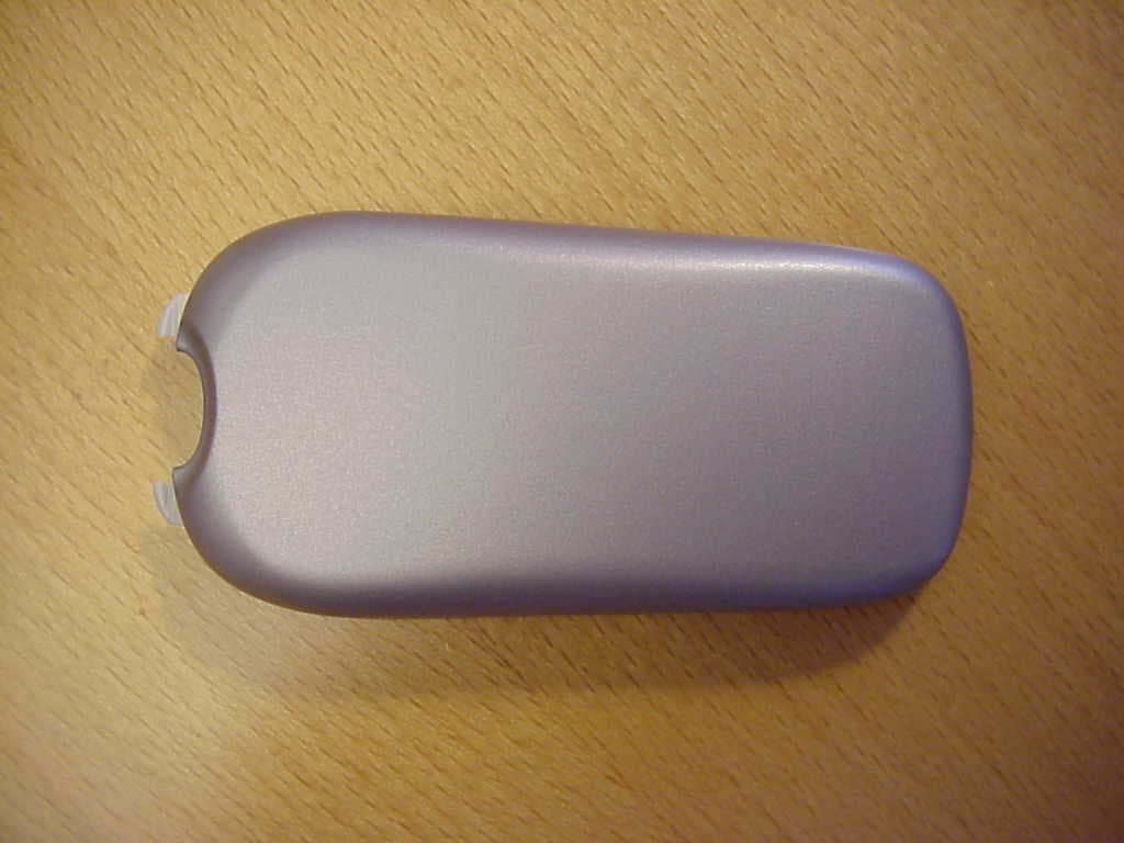
O2OBTP2M100
Jul 16, 2002Motorola Bluetooth Phone Module
Equipment Class
DSS - Part 15 Spread Spectrum Transmitter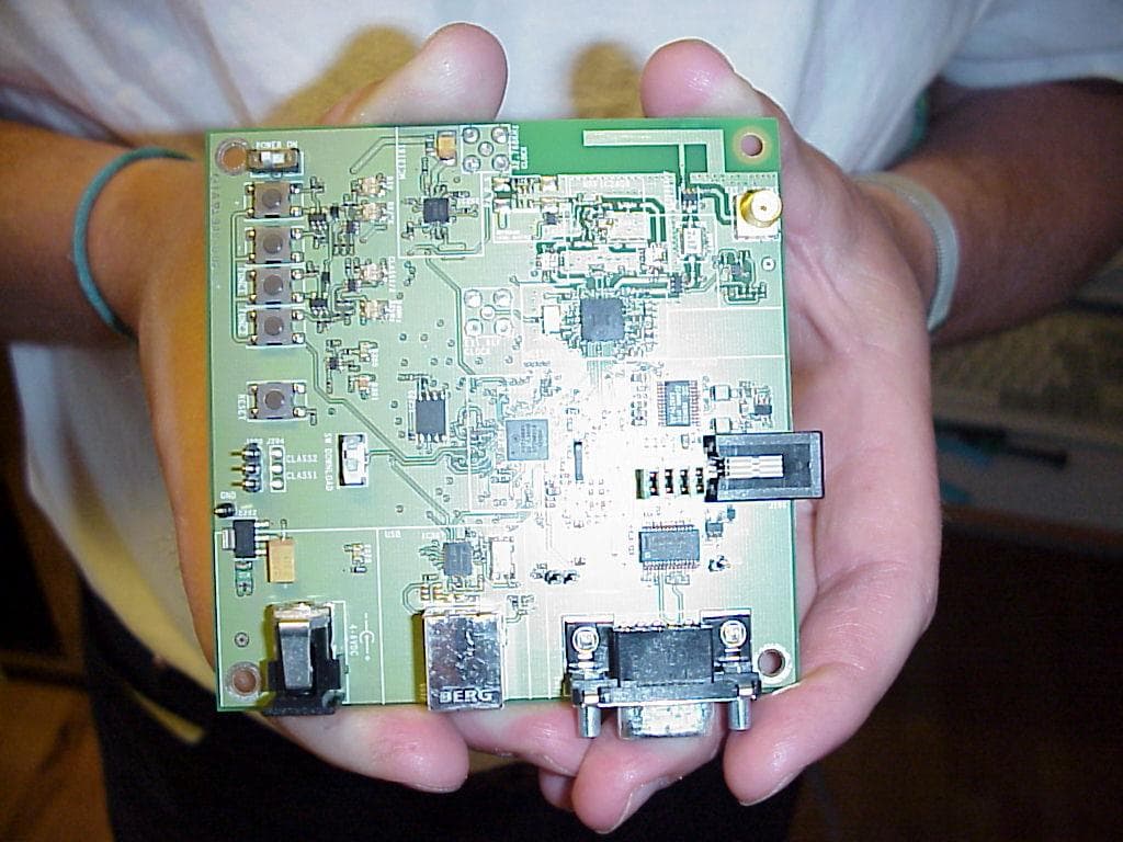
O2OBTDVK100
Jun 27, 2002Bluetooth Developer Kit
Equipment Class
JBP - Part 15 Class B Computing Device Peripheral