O2OSYN8705AMotorola Bluetooth Phone Base unit - SYN8705A
Digianswer A/S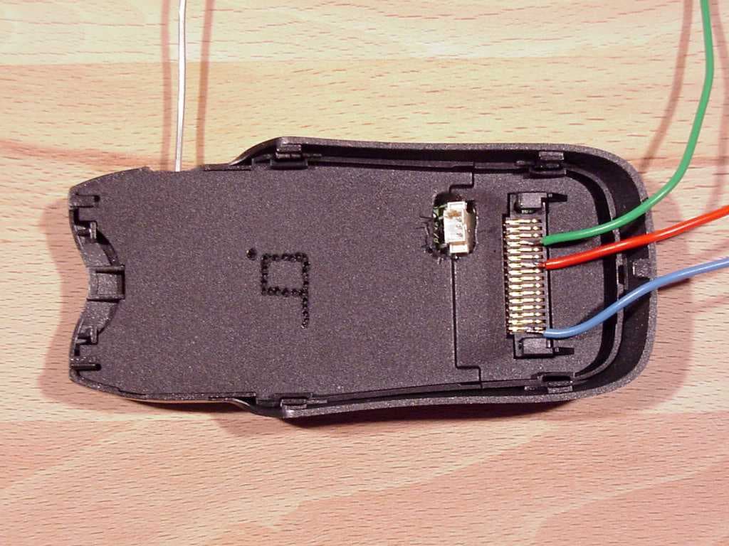
Click to zoom
Application Details
- Equipment Class
- DSS - Part 15 Spread Spectrum Transmitter
- Date of Grant
- Mar 18, 2001
- Application Purpose
- Original Equipment
- Date of Application
- Nov 01, 2000
- Equipment Note
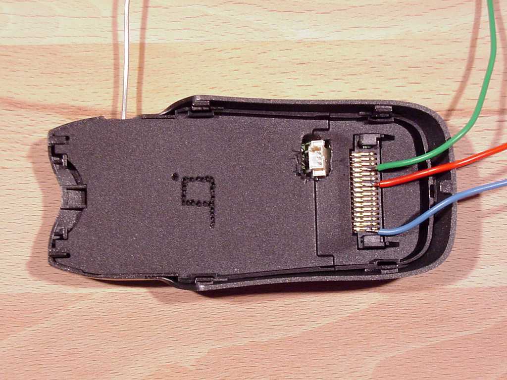
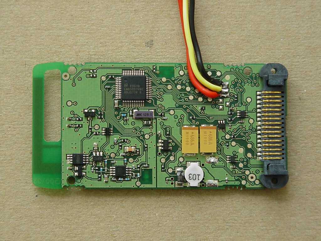
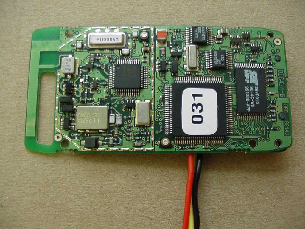
- Motorola Bluetooth Phone Base unit - SYN8705A
- Frequency Range
- 2402.00000000 - 2480.00000000
- Company
- Digianswer A/S
- Country
- Denmark
Documents & Files
Document Text
Text extracted from the exhibit documents filed with the FCC. Open a document above to read the original.
Users Manual
Bluetooth Module User’s Guide January 18, 2001 Bluetooth.book Page 1 Thursday, January 18, 2001 4:43 PM Bluetooth.book Page 2 Thursday, January 18, 2001 4:43 PM Welcome Welcome to Motorola’s “connected” world of Bluetooth personal area wireless networking. We are pleased you have chosen the Motorola Bluetooth Phone Module to keep you connected with ease. The Bluetooth Phone Module enables you to exchange data and/or audio seamlessly between your cellular telephone and other Bluetooth devices such as PDAs or notebook computers. All Motorola wireless products are designed and manufactured to meet Motorola’s rigorous specifications and world-class quality standards. During development, our testing team took the Motorola Bluetooth Phone Module through rigorous durability tests including temperature, humidity, shock, dust, vibration, and drop tests—and it worked perfectly. We are confident that you will find your Bluetooth Phone Module to be a convenient and secure way to exchange voice signals and other data. Thank you for choosing a Motorola Bluetooth product! Bluetooth.book Page 1 Thursday, January 18, 2001 4:43 PM 2 Personal Communications Sector 600 North U.S. Highway 45 Libertyville, Illinois 60048 1-800-331-6456 (United States) 1-888-390-6456 (TTY/TDD United States) 1-800-461-4575 (Canada) www.motorola.com MOTOROLA, the Stylized M Logo and all other trademarks indicated as such herein are trademarks of Motorola, Inc. ® Reg. U.S. Pat. & Tm. Off. All other product or service names are the property of their respective owners. © 2001 Motorola, Inc. All rights reserved. Printed in the U.S.A. Manual number:xxxxxxx Cover number: Bluetooth.book Page 2 Thursday, January 18, 2001 4:43 PM 3 Contents Safety and General Information . . . . . . . . . . . . . . . . . . . . . . . . . . . . . . . . . . 4 Electromagnetic Interference/Compatibility . . . . . . . . . . . . . . . . . . . . . . . . . . . . 4 Getting Started . . . . . . . . . . . . . . . . . . . . . . . . . . . . . . . . . . . . . . . . . . . . . . . . 7 What Is Bluetooth? . . . . . . . . . . . . . . . . . . . . . . . . . . . . . . . . . . . . . . . . . . . . . 7 Attaching the Module to Your Phone . . . . . . . . . . . . . . . . . . . . . . . . . . . . . . . . 8 Bluetooth Menus . . . . . . . . . . . . . . . . . . . . . . . . . . . . . . . . . . . . . . . . . . . . . . . 9 Naming Your Module . . . . . . . . . . . . . . . . . . . . . . . . . . . . . . . . . . . . . . . . . . . 10 Turning Voice Dial On and Off . . . . . . . . . . . . . . . . . . . . . . . . . . . . . . . . . . . . 11 Linking Devices . . . . . . . . . . . . . . . . . . . . . . . . . . . . . . . . . . . . . . . . . . . . . . . 12 Starting a Link to Another Device . . . . . . . . . . . . . . . . . . . . . . . . . . . . . . . . . . 12 Ending a Link . . . . . . . . . . . . . . . . . . . . . . . . . . . . . . . . . . . . . . . . . . . . . . . . 15 Receiving a Link from Another Device . . . . . . . . . . . . . . . . . . . . . . . . . . . . . . 16 Managing Your Device List . . . . . . . . . . . . . . . . . . . . . . . . . . . . . . . . . . . . . . . 18 Ensuring Successful Fax Transmission . . . . . . . . . . . . . . . . . . . . . . . . . . . . . . . 21 Troubleshooting . . . . . . . . . . . . . . . . . . . . . . . . . . . . . . . . . . . . . . . . . . . . . . . 22 Bluetooth.book Page 3 Thursday, January 18, 2001 4:43 PM 4 Safety and General Information IMPORTANT INFORMATION ON SAFE AND EFFICIENT OPERATION. READ THIS INFORMATION BEFORE USING YOUR PHONE. Users are not permitted to make changes or modify the device in any way. Changes or modifications not expressly approved by the party responsible for compliance could void the user’s authority to operate the equipment. See 47 CFR Sec. 15.21. This device complies with part 15 of the FCC Rules. Operation is subject to the following two conditions: (1) This device may not cause harmful interference, and (2) this device must accept any interference received, including interference that may cause undesired operation. See 47 CFR Sec. 15.19(3). Electromagnetic Interference/Compatibility Note: Nearly every electronic device is susceptible to electromagnetic interference (EMI) if inadequately shielded, designed, or otherwise configured for electromagnetic compatibility. Facilities To avoid electromagnetic interference and/or compatibility conflicts, turn off your phone in any facility where posted notices instruct you to do so. Hospitals or health care facilities may be using equipment that is sensitive to external RF energy. Bluetooth.book Page 4 Thursday, January 18, 2001 4:43 PM 5 Safety and General Information Aircraft When instructed to do so, turn off your phone when on board an aircraft. Any use of a phone must be in accordance with applicable regulations per airline crew instructions. Medical Devices Pacemakers The Health Industry Manufacturers Association recommends that a minimum separation of 6 inches (15 centimeters) be maintained between a handheld wireless phone and a pacemaker. These recommendations are consistent with the independent research by, and recommendations of, Wireless Technology Research. Persons with pacemakers should: • ALWAYS keep the phone and Bluetooth phone module more than six inches (15 centimeters) from your pacemaker when the phone is turned ON. • NOT carry the phone and Bluetooth phone module in the breast pocket. • use the ear opposite the pacemaker to minimize the potential for interference. • turn OFF the phone immediately if you have any reason to suspect that interference is taking place. Bluetooth.book Page 5 Thursday, January 18, 2001 4:43 PM Safety and General Information 6 Other Medical Devices If you use any other personal medical device, consult the manufacturer of your device to determine if it is adequately shielded from RF energy. Your physician may be able to assist you in obtaining this information. Bluetooth.book Page 6 Thursday, January 18, 2001 4:43 PM 7 Getting Started What Is Bluetooth? Bl…
Text truncated - open the document above for the full version.
Attestation Statements
Note : The following test results relate only to the devices specified in this document. This report shall not be reproduced in parts without the written approval of the testing laboratory Answer Applicant: Digianswer A/S Skalhuse 5 DK-9240 Nibe Test Laboratory: 7 layers AG Borsigstrasse. 11 D-40880 Ratingen Germany Telephone: +49 (0) 2102 749 100 Fax: +49 (0) 2102749 111 Registergericht h registered in:Vorstand h Board of Directors:7 layers AG, Borsigstrasse 11 Ratingen, HRB 3264Dr. Wolfgang Dahm40880 Ratingen, Germany AufsichtsratsvorsitzendehDr. Hans-Jürgen MeckelburgPhone: +49 (0) 2102 749 0 Chairman of the Supervisory Board:Fax: +49 (0) 2102 749 350 Dr. Sabine Grobeckerwww.7Layers.com Note : The following test results relate only to the devices specified in this document. This report shall not be reproduced in parts without the written approval of the testing laboratory To:Torsten Lohoff, null From:Joe Dichoso [email protected] FCC Application Processing Branch Re:FCC ID O2OSYN8705A Applicant:Digianswer A/S Correspondence Reference Number:17512 731 Confirmation Number:EA99205 Verify that the frequency range from the center frequency of the lowest channel to the center frequency of the highest channel is 2402-2480 MHz. 7layers: See separate document Annex „Additional declaration part according FCC 15.247 for BT devices „ section 2. Provide a Manual. 7layers: A manual has been uploaded seperately. The requested conducted Output power is 2.43 mW. While the test data shows only .37 dBm(1.09 mW). Please explain/correct accordingly. 7layers: Due to the fact that the conducted output power (max. on 2402 MHz is 0.37 dBm (1.09 mW), see test report 4_DIGI_0100_BT_FCCa) will be authorized in the grant, please change the output power in the application to 1,1 mW. Verify that you are not requesting modular approval. 7layers: We do not apply for modular approval. Provide a technical description. If this is confidential, provide a new confidential letter. 7layers: A technical description has been uploaded seperately. Note : The following test results relate only to the devices specified in this document. This report shall not be reproduced in parts without the written approval of the testing laboratory The RF safety requirements depend on whether or not you are requesting modular approval and if the device can transmit simultaneously with the mobile phone. Please explain. Further RF safety review will commence once this is clarified. 7layers: The Bluetooth transmitter can transmit simultaneously with the mobile phone. Due to the low output power of the Bluetooth transmitter (1.09 mW) the Bluetooth device will not exceed the MPE and SAR limits. Provide the following with regard to the device operating in the data mode(FHSS) a) The transmitter cannot coordinate its hopping sequence with the hopping sequence of other transmitters, or vice versa, for the purpose of avoiding the simultaneous occupancy of individual hopping frequencies by multiple transmitters. Provide a description on how the device complies with this rule. 7layers: See separate document Annex „Additional declaration part according FCC 15.247 for BT devices „ section 3. b) The system shall hop to channel frequencies that are selected at the system hopping rate from a pseudorandomly ordered list of hopping frequencies. Indicate how the pseudorandom hopping sequence is derived. Provide a list of channel frequencies and a sample of a few sequences. 7layers: See separate document Annex „Additional declaration part according FCC 15.247 for BT devices „ section 4. c) Each frequency must be used equally on the average by each transmitter. Except for voice systems, each new transmission may not start at the same point in the sequence or the frequencies will not be used equally used. Therefore, Describe where the next transmission starts when all frequencies are not used for a previous message. This is required because some transmissions may need only a few frequency hops to be completed. i.e. If the transmission started on the same frequency each time, this frequency would be used more than the others if many short transmissions were sent. 7layers: See separate document Annex „Additional declaration part according FCC 15.247 for BT devices „ section 5. Note : The following test results relate only to the devices specified in this document. This report shall not be reproduced in parts without the written approval of the testing laboratory d) Section 15.247(a)1 indicates that the system receivers shall have input bandwidths that match the hopping channel bandwidths of their corresponding transmitters and shall shift frequencies in synchronization with the transmitted signals. Please explain how the device complies with this rule when a packet is repeated or when multiple packets are sent. What is the receiver input bandwidth? How does the receiver shift frequencies and determine which frequency to shift to in order to synchronize with this transmitter? 7layers: See separate document Annex „Additional declaration part according FCC 15.247 for BT devices „ section 6. e) Compliance with the dwell time requirement. 7layers: See separate document Annex „Additional declaration part according FCC 15.247 for BT devices „ section 7. Provide the following information with regard to the device operating in the page and inquiry mode under the Spread spectrum Hybrid requirements in Section 15.247(f) and Section 15.247(a)1. f) Compliance with the minimal channel separation. 7layers: See separate document Annex „Additional declaration part according FCC 15.247 for BT devices „ section 8. g) 20 dB bandwidth plot. Note : The following test results relate only to the devices specified in this document. This report shall not be reproduced in parts without the written approval of the testing laboratory Ref Lvl 21.3 dBm Ref Lvl 21.3 dBm RF Att 30 dB 1.3 dB Offset 1.3 dB Offset A UnitdBm 1MAX SWT 76 ms Center2.441 GHzSpan3 MHz300 kHz/ RBW 10 kHz VBW 30 kHz IN1 1MA 1MA…
Text truncated - open the document above for the full version.
Attestation Statements
Registergerichth registered in:Vorstandh Board of Directors:7 layers AG, Borsigstrasse 11 Ratingen HRB 3264Dr. Wolfgang Dahm40880 Ratingen, Germany AufsichtsratsvorsitzendehDr. Hans-Jürgen MeckelburgPhone: +49 (0) 2102 749 0 Chairman of the Supervisory Board:Fax: +49 (0) 2102 749 350 Dr. Sabine Grobeckerwww.7layers.com Annex Additional declaration part according FCC 15.247 for Bluetooth devices Version: 2000-01-11 (Annex - Additional declaration part according FCC 15.247 for Bluetooth devices) Page 2 of 5 pages 1 Output power and channel separation of a Bluetooth device in the different operating modes: The different operating modes (data-mode, acquisition-mode) of a Bluetooth device don’t influence the output power and the channel spacing. There is only one transmitter which is driven by identical input parameters concerning these two parameters. Only a different hopping sequence will be used. For this reason the check of these RF parameters in one op-mode is sufficient. 2 Frequency range of a Bluetooth device: Hereby we declare that the maximum frequency of this device is: 2402 – 2480 MHz. This is according the Bluetooth Core Specification V 1.0B (+ critical errata) for devices which will be operated in the USA. This was checked during the Bluetooth Qualification tests (Test Case: TRM/CA/04-E). Other frequency ranges ( e.g. for Spain, France, Japan) which are allowed according the Core Specification are not supported by this device. 3 Co-ordination of the hopping sequence in data mode to avoid simultaneous occupancy by multiple transmitters: Bluetooth units which want to communicate with other units must be organised in a structure called piconet. This piconet consist of max. 8 Bluetooth units. One unit is the master the other seven are the slaves. The master co-ordinates frequency occupation in this piconet for all units. As the master hop sequence is derived from it’s BD address which is unique for every Bluetooth device, additional masters intending to establish new piconets will always use different hop sequences. 4 Example of a hopping sequence in data mode: Example of a 79 hopping sequence in data mode: 40, 21, 44, 23, 42, 53, 46, 55, 48, 33, 52, 35, 50, 65, 54, 67, 56, 37, 60, 39, 58, 69, 62, 71, 64, 25, 68, 27, 66, 57, 70, 59, 72, 29, 76, 31, 74, 61, 78, 63, 01, 41, 05, 43, 03, 73, 07, 75, 09, 45, 13, 47, 11, 77, 15, 00, 64, 49, 66, 53, 68, 02, 70, 06, 01, 51, 03, 55, 05, 04 (Annex - Additional declaration part according FCC 15.247 for Bluetooth devices) Page 3 of 5 pages 5 Equally average use of frequencies in data mode and behaviour for short transmissions: The generation of the hopping sequence in connection mode depends essentially on two input values: 1. LAP/UAP of the master of the connection 2. Internal master clock The LAP (lower address part) are the 24 LSB’s of the 48 BD_ADDRESS. The BD_ADDRESS is an unambiguous number of every Bluetooth unit. The UAP (upper address part) are the 24 MSB’s of the 48 BD_ADDRESS. The internal clock of a Bluetooth unit is derived from a free running clock which is never adjusted and is never turned off. For synchronisation with other units only offset are used. It has no relation to the time of the day. Its resolution is at least half the RX/TX slot length of 312.5 μs. The clock has a cycle of about one day (23h30). In most case it is implemented as 28 bit counter. For the deriving of the hopping sequence the entire LAP (24 bits), 4 LSB’s (4 bits) (Input 1) and the 27 MSB’s of the clock (Input 2) are used. With this input values different mathematical procedures (permutations, additions, XOR- operations) are performed to generate the sequence. This will be done at the beginning of every new transmission. Regarding short transmissions the Bluetooth system has the following behaviour: The first connection between the two devices is established, a hopping sequence was generated. For transmitting the wanted data the complete hopping sequence was not used. The connection ended. The second connection will be established. A new hopping sequence is generated. Due to the fact that the Bluetooth clock has a different value, because the period between the two transmission is longer (and it cannot be shorter) than the minimum resolution of the clock (312.5 μs). The hopping sequence will always differ from the first one. 6 Receiver input bandwidth and behaviour for repeated single or multiple packets: The input bandwidth of the receiver is 1 MHz. In every connection one Bluetooth device is the master and the other one is the slave. The master determines the hopping sequence (see chapter 5). The slave follows this sequence. Both devices shift between RX and TX time slot according to the clock of the master. Additionally the type of connection (e.g. single or multislot packet) is set up at the beginning of the connection. The master adapts its hopping frequency and its TX/RX timing according to the packet type of the connection. Also the slave of the connection will use these settings. Repeating of a packet has no influence on the hopping sequence. The hopping sequence generated by the master of the connection will be followed in any case. That means, a repeated packet will not be send on the same frequency, it is send on the next frequency of the hopping sequence. (Annex - Additional declaration part according FCC 15.247 for Bluetooth devices) Page 4 of 5 pages 7 Dwell time in data mode The dwell time of 0.3797s within a 30 second period in data mode is independent from the packet type (packet length). The calculation for a 30 second period is a follows: Dwell time = time slot length * hop rate / number of hopping channels *30s Example for a DH1 packet (with a maximum length of one time slot) Dwell time = 625 μs * 1600 1/s / 79 * 30s = 0.3797s (in a 30s period) For multislot packet the hopping is reduced according to the length of the packet. Example for a DH5 packet (with a maximum length of five time slots) Dwell time = 5 * 625 μs * 1600 * 1/5 *1/s /…
Text truncated - open the document above for the full version.
Attestation Statements
Registergericht h registered in:Vorstand h Board of Directors:7 layers AG, Borsigstrasse 11 Ratingen, HRB 3264Dr. Wolfgang Dahm40880 Ratingen, Germany AufsichtsratsvorsitzendehDr. Hans-Jürgen MeckelburgPhone: +49 (0) 2102 749 0 Chairman of the Supervisory Board:Fax: +49 (0) 2102 749 350 Dr. Sabine Grobeckerwww.7Layers.com 27.02.2001 Phone +49 (0) 2102 749 306 Fax +49 (0) 2102 749 350 reference no: 18219, 731 confirmation number: EA99205 Dear Sirs, thank you very much for your response dated 26.02.01. In your email you asked us about the labelling of the phone module with regard to the labelling of the cellular phone connected to the phone module. Please be informed that the module itself and the cellular phone will be labelled seperately. This is the reason why the phone module label will not contain any information about the cellular phone. The phone module will be labelled according to the label layout uploaded on 06.11.00. The phone module will be used with various cellular phones in the future and it is not possible to give a list of cellular phones it will be used with at this time. Because the labelling will be done as mentioned above, labelling requirements for cellular phones to not have to be considered for the phone module label. I hope this clarifies the labelling issue. Thank you very much Best Regards Torsten Lohoff FCC Equipment Authorization Branch Projektname: 3_DIGI_PHONE_01
ID Label/Location Info
Bluetooth Phone Module 0023606-0091655 Model: SYN8705A TM FCC ID: O2OSYN8705A CANADA: Bluetooth Phone Module 0023606-0091655 Model: SYN8705A TM Made in Scotland CANADA: Made in Scotland FCC ID: O2OSYN8705A
Operational Description
Digianswer / Motorola Phone Module Date: 01.01.14 Author: TR Rev: 1.0 Project: 93 Part Number: SYN8705A Subject: Product Specification. Page: 1 of 9 Digianswer / Motorola Phone Module Product Specification Revision history: Version Date Author Description 1.0 01.01.14 Tom Ringtved Initiating project specification Digianswer / Motorola Phone Module Date: 01.01.14 Author: TR Rev: 1.0 Project: 93 Part Number: SYN8705A Subject: Product Specification. Page: 2 of 9 CONTENTS 1. SCOPE.................................................................................................................................................3 2. DESCRIPTION AND APPLICATION............................................................................................3 3. APPLICABLE DOCUMENTS.........................................................................................................3 4. FUNCTIONAL DESCRIPTION......................................................................................................4 4.1. PLATFORM FUNCTIONS AND LIMITATIONS......................................................................................4 4.1.1. Mobile phone interface module.......................................................................................4 4.1.2. Bluetooth module...............................................................................................................4 4.1.3. MMI module........................................................................................................................4 4.2. HARDWARE OVERVIEW...................................................................................................................4 4.3. FIRMWARE OVERVIEW....................................................................................................................5 5. MECHANICAL DESCRIPTION.....................................................................................................6 5.1. FORM FACTOR................................................................................................................................6 5.2. LABELLING.....................................................................................................................................6 6. ELECTRICAL DESCRIPTION.......................................................................................................6 6.1. CONNECTOR DESCRIPTION...............................................................................................................6 6.2. ELECTRICAL COMPATIBILITY...........................................................................................................6 6.3. CARD AND SOCKET SERVICES..........................................................................................................6 6.4. SUPPORTED PROFILES......................................................................................................................7 7. END-USER DOCUMENTATION....................................................................................................7 7.1. PRINTED DOCUMENTATION............................................................................................................7 7.1.1. Installation Guide..............................................................................................................7 7.1.1.1. Installing your Hardware.......................................................................................................7 7.1.1.2. Installing the Application Software.........................................................................................7 8. RETAIL PACKING............................................................................................................................7 8.1. PHYSICAL DIMENSIONS...................................................................................................................7 8.2. DESIGN AND LAYOUT......................................................................................................................7 8.3. LANGUAGE VERSIONING..................................................................................................................7 9. DELIVERABLES...............................................................................................................................7 10. TIME SCHEDULE.........................................................................................................................9 11. COST CALCULATIONS...............................................................................................................9 12. QUALITY, CONFORMANCE AND COMPLIANCE TESTING..........................................9 12.1. BLUETOOTH LOGO CERTIFICATION..............................................................................................9 12.2. SAFETY APPROVALS....................................................................................................................9 12.3. TYPE APPROVALS........................................................................................................................9 12.4. WHQL COMPLIANCE.................................................................................................................9 12.5. ENVIRONMENTAL TESTING..........................................................................................................9 Digianswer / Motorola Phone Module Date: 01.01.14 Author: TR Rev: 1.0 Project: 93 Part Number: SYN8705A Subject: Product Specification. Page: 3 of 9 1. Scope. This document serves as a product specification of the “Motorola Bluetooth™ Phone Module”, defining software- hardware architecture, interfaces, functions and limitations. This document is intended for internal definition of the project and as an external introduction to the product. Included is a definition of the intended retail level of this product, in respect to country support and top-level contents. 2. Description and application. The “Motorola Bluetooth™ Phone Module” is…
Text truncated - open the document above for the full version.
Test Report
EMC Measurement/Technical Report 4_DIGI_0100_BT_FCCa on 7 Layers AG Borsigstr. 11 40880 Ratingen Germany Note: The following test results relate only to the devices specified in this document. This report shall not be reproduced in parts without the written approval of the testing laboratory. Digianswer Bluetooth(TM) Phone Module DIG434-6 Registergericht - registered in: Ratingen, HRB 3264 Aufsichtratsvorsitzende - Chairman of the Supervisory Board: Dr. Sabine Grobecker Vorstand - Board of Directors: Dr. Wolfgang Dahm Dr. Hans-Jürgen Meckelburg 7 layers AG, Borsigstrasse 11 40880 Ratingen, Germany Phone: +49 (0) 2102 749 0 Fax: +49 (0) 2102 749 350 http://www.7Layers.com Report Reference: Table of Contents 0. Summary 0.1 Technical Report Summary 0.2 Measurement Summary 1. Administrative Data 1.1 Testing Laboratory 1.2 Project Data 1.3 Applicant Data 1.4 Manufacturer Data 3. Testobject Data 3.1 General EUT Description 3.2 EUT Main Components 3.3 Ancillary Equipment 3.4 EUT Setups 3.5 Operating Modes 4. Measurement Results 4.1 Conducted Emissions 4.2 Occupied Bandwidth 4.3 Output Power 4.4 Spurious Emissions Conducted 5. Testequipment 6. Foto Report 7. Setup Drawings 8. Annex 3 3 4 6 6 6 6 6 8 8 9 9 9 9 11 11 13 15 17 29 31 33 36 Measurement plots 4.5 Spurious Emissions Radiated19 2. Product Labeling 2.1 FCC ID Label 2.2 Location of Label on the EUT 7 7 7 4.6 Dwell Time 4.7 Power Density 4.8 Channel Separation 4.9 Processing Gain 23 25 27 28 Page 2 of 56 Testreport Reference: 4_DIGI_0100_BT_FCCa 0 Summary 0.1 Technical Report Summary Type of Authorization Certification for an Intentional Radiator (Frequency Hopping Spread Spectrum) Applicable FCC Rules: Prepared in accordance with the requirements of FCC Rules and Regulations as listed in 47 CFR Ch.1 Parts 0 to 19 (10-1-98 Edition). The following subparts are applicable to the results in this test report. Part 2, Subpart J - Equipment Authorization Procedures, Certification Sections Part 15, Subpart C - Intentional Radiators § 15.201 Equipment authorization requirement § 15.203 Antenna requirements § 15.207 Conducted limits § 15.209 Radiated emission limits; general requirements § 15.247 Operation within the bands 902-928 MHz, 2400-2483,5 MHZ and 5725-5850 MHz Summary Test Results: The EUT complied with all the applicable FCC rules as listed above. Note: The tests were selected and performed with reference to the FCC Public Notice DA 00- 705, released March 30, 2000 Page 3 of 56 Testreport Reference: 4_DIGI_0100_BT_FCCa 0.2 Measurement Summary § 15.207FCC Part 15, Subpart C ANSI C63.41992The measurement was performed according to Conducted Emissions (AC Power Line)Conducted Emissions (AC Power Line) OP-ModeOP-ModeSetupSetupPortPortFinal ResultFinal Result setup2op-mode 2AC portpassed § 15.247 (a) (1) (ii)FCC Part 15, Subpart C ANSI C63.41992The measurement was performed according to Occupied BandwidthOccupied Bandwidth OP-ModeOP-ModeSetupSetupPortPortFinal ResultFinal Result setup1op-mode 1Antenna portpassed setup1op-mode 2Antenna portpassed setup1op-mode 3Antenna portpassed § 15.247 (b) (1)FCC Part 15, Subpart C FCC §15.3110-1-1998The measurement was performed according to Peak Power OutputPeak Power Output OP-ModeOP-ModeSetupSetupPortPortFinal ResultFinal Result setup1op-mode 1Antenna portpassed setup1op-mode 2Antenna portpassed setup1op-mode 3Antenna portpassed § 15.247 (c)FCC Part 15, Subpart C FCC §15.3110-1-1998The measurement was performed according to Spurious RF Conducted EmissionsSpurious RF Conducted Emissions OP-ModeOP-ModeSetupSetupPortPortFinal ResultFinal Result setup1op-mode 1Antenna portpassed setup1op-mode 2Antenna portpassed setup1op-mode 3Antenna portpassed § 15.247 (c), §15.35 (b), § 15.209FCC Part 15, Subpart C ANSI C63.41992The measurement was performed according to Spurious Radiated EmissionsSpurious Radiated Emissions OP-ModeOP-ModeSetupSetupPortPortFinal ResultFinal Result setup 3op-mode 1enclosurepassed setup 3op-mode 2enclosurepassed setup 3op-mode 3enclosurepassed § 15.247(g)FCC Part 15, Subpart C Page 4 of 56 Testreport Reference: 4_DIGI_0100_BT_FCCa FCC §15.3110-1-1998The measurement was performed according to Dwell TimeDwell Time OP-ModeOP-ModeSetupSetupPortPortFinal ResultFinal Result setup1op-mode 4Antenna portpassed setup1op-mode 5Antenna portpassed § 15.247 (g)FCC Part 15, Subpart C FCC §15.3110-1-1998The measurement…
Text truncated - open the document above for the full version.
Contact Information
Applicant
Jorgen Holst(Functional Manager, Platform & IT)
Technical Contact
Non-Technical Contact
Digianswer A/STom Ringtved
[email protected]+45 96 710025
Test Firm
7layers AGRobert Machulec
Technical Specifications
| # | Rule Parts | Frequency Range | Power Output | Tolerance |
|---|---|---|---|---|
| 1 | 15C | 2.40 GHz - 2.48 GHz | 1.10 mW | Hz |
Other Applications from Digianswer A/S
O2O13192-EVB
Sep 21, 2004WPAN Transceiver
Equipment Class
DTS - Digital Transmission System
O2O13192-SARD
Aug 24, 2004IEEE 802.15.4 Transceiver
Equipment Class
DTS - Digital Transmission System
O2OBTDVK110
Jan 22, 2003Bluetooth Developer Kit
Equipment Class
DSS - Part 15 Spread Spectrum Transmitter
O2OBTP2M100
Jul 16, 2002Motorola Bluetooth Phone Module
Equipment Class
DSS - Part 15 Spread Spectrum Transmitter
O2OBTDVK100
Jun 27, 2002Bluetooth Developer Kit
Equipment Class
JBP - Part 15 Class B Computing Device Peripheral