O2SNURIT3010CPoint of Sale Device
Verifone Inc.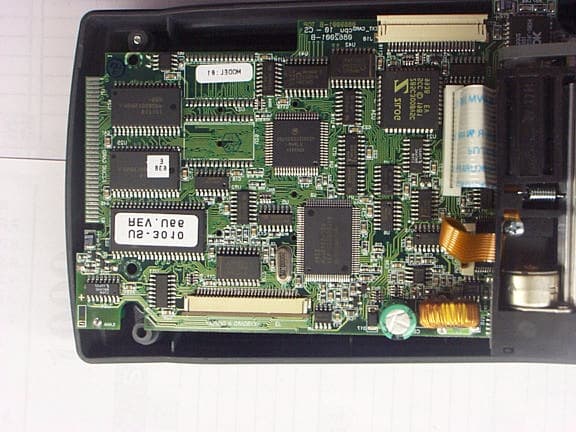
Click to zoom
Application Details
- Equipment Class
- TNB - Licensed Non-Broadcast Station Transmitter
- Date of Grant
- Oct 25, 2000
- Application Purpose
- Original Equipment
- Date of Application
- Aug 27, 2000
- Equipment Note
- Point of Sale Device
- Frequency Range
- 824.00000000 - 849.00000000
- Company
- Verifone Inc.
- Country
- United States
Documents & Files
Document Text
Text extracted from the exhibit documents filed with the FCC. Open a document above to read the original.
Users Manual
August 2000 Exhibit 9 Nurit 3010/CDPD Point of Sale Device Lipman USA FCC ID: O2SNURIT3010C User’s Manual 082-32-001 NURIT /3010 User Manual1 NURIT 3010 POS/EDC TERMINAL USER MANUAL NURIT 3010 POS/EDC TERMINAL USER MANUAL NOTICEThe information contained in this publication is for informational purposes only and subject to change without notice. It does not represent a commitment on the part of Lipman USA Inc. or Lipman Electronic Engineering Ltd. No part of this publication may be reproduced, transmitted, transcribed, stored in a retrieval system, or translated to any language in any form by any means without the prior written permission of Lipman. Copyright © 1999 by Lipman Electronic Engineering Ltd. All rights reserved. TRADEMARKSTrademarks and trade names contained in this manual belong to their respective companies. LIPMAN USA INC.January 1999 50 Gordon DriveOriginal Syosset, NY 11791Publication No. 082-32-001 Tel: (1) 516-484-9898 Fax: (1) 516-484-9057 E-mail: [email protected] 082-32-001 WARNING Changes or modifications to this unit not expressly approved by the party responsible for compliance could void the user's authority to operate the equipment. FCC compliance statement This equipment has been tested to be found to comply with the limits for class A digital device, pursuant to Part 15 of the FCC Rules. Operation is subject to the following conditions: (1) This device may not cause harmful interference, and (2) this device must accept any interference received, including interference that may cause undesired operation. Class A limits are designed to provide reasonable protection against harmful interference in a residential installation. This equipment generates, uses and can radiate radio frequency energy and, if not installed and used in accordance with the instructions, may cause interference to radio communications. However, there is no guarantee that interference will not occur in a particular installation. If this equipment does cause harmful interference to radio or television reception, which can be determined by turning the equipment off and on, the user is encouraged to try to correct the interference by one or more of the following measures: • Reorient or relocate the receiving antenna. • Increase the separation between the equipment and the receiver. • Connect the equipment into an outlet on a circuit different from that to which the receiver is connected. • Consult your dealer or an experienced technician for help. FCC requirements The Federal Communications Commission (FCC) has established rules permitting this device to be directly connected to the telephone network. Standardized jacks are used for these connections. This equipment should not be used on party or coin lines. If this devise is malfunctioning, it may be causing harm to the telephone network; this devise should be disconnected until the source of the problem can be determined and until repair has been made. If this is not done, the telephone company may temporarily disconnect service. The telephone company may make changes in its technical operations and procedures; if such changes affect the compatibility or use of this devise, the telephone company is required to give adequate notice of the changes. You will be advised to file a complaint with the FCC. If the telephone company requests information on what equipment is connected to their lines, inform them of: One. The telephone number this unit is connected to Two. The ringer equivalence number: 0.3B Three. The USOC jack required: RJ-11C Four. The FCC Registration number: 3D7ISR-25066-DT-E The Ringer Equivalence Number (REN) is used to determine how many devices can be connected to your telephone line. In most areas, the sum of the RENs of all devices on any one line should not exceed five (5). If too many devices are attached, they may not ring properly. FCC Part 15 Requirements Notice • This device must not be installed on coin-operated telephone lines or party lines. • This device (equipment) complies with the requirements in Part 15 of FCC Rules of a Class B computing device. Operation of this device (equipment) is subject to the following two conditions: o This device (equipment) may not cause harmful interference, and o This device (equipment) must accept any interference received, including interference that may cause undesired operation. • If this device (equipment) is used in a residential area, it may cause unacceptable interference to radio and TV reception requiring the operator to take whatever steps necessary to correct the interference. • Repair work on this device (equipment) must by done by Lipman USA, Inc, or an authorized repair station. 082-32-001 LIPMAN USA - NURIT /3010 Limited Warranty Lipman USA Inc. will repair this product with new or rebuilt parts, free of charge, in the U.S.A. for one (1) year from the date of original purchase in the event of a defect in materials or workmanship. Carry-in or mail-in service in the continental U.S.A. can be obtained during the warranty period from our N.Y. Service Center or call 1-800-4-LIPMAN toll free. In New York State call (516) 484-9898. This warranty is extended only to the original purchaser. A purchase receipt or other proof of date of original purchase will be required in order to exercise your rights under this warranty. This warranty only covers failures due to defects in materials or workmanship which occur during normal use. It does not cover damage which occurs in shipment; failures which are caused by products not supplied by Lipman USA; or failures which result from accident, misuse, abuse, neglect, mishandling, misapplication, alteration or modification; service by anyone other than the Lipman USA Service Center or accredited service centers, or damage that is attributable to acts of God. Limits and Exclusions There are no express warranties except as listed above. LIPMAN USA SHALL NOT BE LIABLE FOR INCIDENTAL OR CONSEQUENTIAL DAMAGES RESULTING FROM THE USE OF T…
Text truncated - open the document above for the full version.
Attestation Statements
March 2000 APREL Project No.: LPMB-NURIT-3010-3371 Exhibit 1 Nurit 3010/CDPD Point of Sale Device Lipman USA, Inc. FCC ID: O2SNURIT3010C Authorization letter Letter requesting Confidentiality Letter from Novatel Wireless Inc. authorizing to use CDPD modem in Lipman Nurit 3010 product
Attestation Statements
August 2000 Consulting * Research * Training * Certification Testing Since 1981 Exhibit 11 Wireless CDPD Modem Nurit 3010 Lipman USA, Inc. FCC ID: O2SNURIT3010C FCC Part 15, Subpart B, Class B Declaration of Conformity Certificate (DoC)
Cover Letter(s)
August 2000 Table of Contents Lipman USA Point of Sale Device Nurit 3010 with a Novatel NRM-6832 Transmitter CDPD FCC ID: O2SNURIT3010C C C O O V V E E R R L L E E T T T T E E R R Exhibit 1: a. Authorization Letter b. Request for confidentiality c. Letter from Novatel Wireless Inc. authorizing to use CDPD modem in Lipman USA Product Exhibit 2/A: Engineering Report for ERP (Includes Test Set-up Photos) Exhibit 2/B: Engineering Report for Spurious (Includes Test Set-up Photos) Exhibit 3: Technical Descriptions and Tune-up Procedure Exhibit 4: FCC ID Label Exhibit 5: Photographs of the Equipment Internal & External Exhibit 6: Block Diagram (Confidential) Exhibit 7: Schematic Diagram (Confidential) Exhibit 8: Parts List (Confidential) Exhibit 9: User’s Manual Exhibit 10: SAR Report (Includes Test Set-up Photographs) (2) Body and Head Exhibit 11: FCC Part 15, Subpart B, DoC letter
Internal Photos
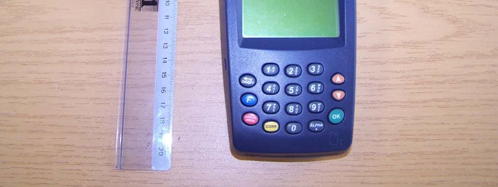
August 2000 Exhibit 5 Nurit 3010/CDPD Point of Sale Terminal Lipman USA FCC ID: O2SNURIT3010C Photographs of the Equipment Internal External August 2000 Lipman USA, Inc. Nurit 3010 CDPD August 2000 Lipman USA Inc.: Nurit 3010 CDPD Back August 2000 Lipman USA, Ltd. Nurit 3010 CDPD Battery compartment open August 2000 Lipman USA, Ltd. Nurit 3010 CDPD: Front August 2000 Lipman USA, Ltd. Nurit 3010 CDPD: Ports August 2000 Lipman USA, Ltd. Nurit 3010 CDPD: Open August 2000 Lipman USA, Ltd. Nurit 3010 CDPD: Back of screen and keyboard August 2000 Lipman USA, Ltd. Nurit 3010 CDPD: Ports August 2000 Lipman USA, Ltd. Nurit 3010 CDPD: Board over modem August 2000 Lipman USA, Ltd. Nurit 3010 CDPD: Modem
Operational Description
August 2000 Exhibit 3 Nurit 3010/CDPD Point of Sale Device Lipman USA FCC ID: O2SNURIT3010C Technical Descriptions and Tune-up Procedure Ref: FCC Parts 2 paragraph 2.983(d) TECHNICAL DESCRIPTION OF THE EQUIPMENT Ref.: FCC Part 2 paragraph 2.983(d) Lipman Nurit 3010 CDPD Point of Sale Device With a Novatel NRM-6832 Transmitter, CDPD Tune-up Procedure at Nominal Operating Power: Limiting Power: The unit integrates the Novatel CDPD module that complies with part 22 under FCCID NBZNRM6832 which will not allow us to exceed the max allowable limit. Circuitry and Devices for Determining and Stabilizing Frequency: Frequency Stabilization: The unit integrates the Novatel CDPD module that complies with part 22 under FCCID NBZNRM6832 which has demonstrated a stability of 1.5 PPM. Suppression of Spurious Radiation: Spurious and harmonic suppression is achieved by proper board layout, power distribution among ground planes and good filtering. We have demonstrated continuous compliance in our factory. Limiting Modulation: The unit integrates the Novatel CDPD module which complies with part 22 under FCCID NBZNRM6832 which will not allow us to alter modulation from the GMSK. Technical Description for the Nurit 3010 Novatel CDPD Unit Preface: The purpose of this document is to give technical information of the POS Terminal: "NURIT- 3010" for FCC regulation. The description is based on the attached block diagram in the last page of this document. General: The unit is built out of three boards: The main or CPU board, the KEYBOARD and the RADIO ADAPTER board. CPU Board: The CPU board includes the following circuits: MAIN power supply: The main power supply produces +5V also called VCC for the logic circuit as well as the modem and also used to drive the display back-light LED. The power supply consists of the MC34063AD PWM controller in a configuration of a buck (step-down) regulator running in a frequency of 40KHz-50KHz. A dc in voltage of 12V to 18V is applied throughout a p- channel FET switch, which is controlled by the PWM controller. The drain of the FET is tied to a Schottky diode and the energy storage inductor. The output of the inductor is tied to voltage divider, which connected to the sense input of the PWM controller. The inductor is also tied to an output filter capacitor and a protection zener diode, then to the powered circuitry. Regulation of +5V is accomplished by variation of the duty-cycle of the switching FET upon sensing the feedback voltage. While running by the UPS batteries, the output voltage of the battery pack (7.2V nominal) is connected via Schottky diode to the input of the power-supply. The main power-supply can work in an input voltage range of 6V-20V. PRINTER power supply: The printer power supply produces 7.65V also called VP for the printer. The power supply consists of the MC34063AD PWM controller in a configuration of a buck (step-down) regulator running in a frequency of 40KHz-50KHz. A dc in voltage is applied throughout a p-channel FET switch, which is controlled by the PWM controller. The drain of the FET is tied to a Schottky diode and the energy storage inductor. The output of the inductor is tied to voltage divider, which connected to the sense input of the PWM controller. The inductor is also tied to an output filter capacitor, and via another FET switch to the powered circuitry. Regulation of 7.65V is accomplished by variation of the duty-cycle of the switching FET upon sensing the feedback voltage. While running by the UPS batteries, the output voltage of the battery pack (7.2V nominal) is connected via Schottky diode to the regulated output of the power-supply. The printer power-supply can work in an input voltage range of 8.5V-20V. PIN-PAD power supply: A 3-lead linear regulator 7809, for the pin-pad circuit regulates the pin-pad power supply to 9V (VPP). While running by the UPS batteries, the output voltage of the battery pack (7.2V nominal), is connected via Schottky diode to the regulated output of the power-supply. The pin-pad power-supply can work in an input dc-in voltage range of 12V-20V. POWER-LOSS detection circuit: The CPU board includes a power-loss detection circuit in order to detect electrical breaks. When the input DC voltage goes below 9V, it is detected by a comperator circuit and signals the CPU by one of the interrupt signals that a power loss occurred. Then, the last status of the terminal is saved. Upon power-up the CPU is being signal for power recovery and the last status is restored. While working on batteries this interrupt is disabled. System processor: The main system processor is a MOTOROLA MC68EC000FU with a 32 bit core, 16-bit data bus and 24-bit address bus. The processor runs with a system clock of 20MHz which is produced by the System ASIC. The processor has 7 different input interrupt sources. All memory devices and I/O devices are located within its 16Mbytes address space. System Memory: The unit includes 1Mbyte program flash memory which can be upgraded to 2Mbytes. The unit includes static RAM from 128Kbytes up to 2Mbytes with hardware write protected feature for sections of the memory. The RAM is backed up with an on-board 3.6V 36mAh NiMH battery. System Real Time Clock (RTC) The System RTC is based on the Seiko S-3510ANFJX chip running with a built in oscillator circuit of a 32Khz. The RTC is working with the main Vcc and backed-up with the same on board NiMh of the RAM. The battery is charged when the unit is turned on. The RTC has a serial I/O interface, which is connected to the system ASIC. System ASIC: The system ASIC has a built-in oscillator, which produces, with an external 20Mhz crystal, the system clock. The ASIC is also controlling the CPU bus timing. The ASIC also includes part of the decoding logic of the system. It produces controlling signals to the printer mechanism and to the graphic display contrast drive circuit. The ASIC has a built-in UART. It has a serial I/O and CLK port for interfacing the RTC as …
Text truncated - open the document above for the full version.
RF Exposure Info
August 2000 Exhibit 10 Nurit 3010/CDPD Point of Sale Device Lipman USA FCC ID: O2SNURIT3010C SAR Report (With Test Set-up Photographs) Certification Report on Specific Absorption Rate (SAR) Experimental Analysis on Hand Lipman USA Incorporated NURIT 3010 CDPD Wireless Point of Sale Device Test Date: 8 Aug 2000 51 Spectrum Way Nepean ON K2R 1E6 Tel: (613) 820-2730 Fax: (613) 820-4161 email: [email protected] This report shall not be reproduced, except in full, without the express written permission of APREL Laboratories LPMB-NURIT 3010 CDPD-3507U Page 2 of 22Project #: LPMB-Nurit 3010 CDPD-3507U 51 Spectrum WayTel. (613) 820-2730 Nepean, Ontario, K2R 1E6Fax (613) 820 4161 e-mail: [email protected] © APREL 2000 This report shall not be reproduced, except in full,without the express written approval of APREL Laboratories. FCC ID:O2SNURIT3010C Applicant:Lipman USA Inc. Equipment:Wireless Point of Sale Terminal with a Novatel NRM-6832 Expedite Wireless IP Modem Model:Nurit 3010, CDPD Standard:FCC 96 –326, Guidelines for Evaluating the Environmental Effects of Radio- Frequency Radiation ENGINEERING SUMMARY This report contains the results of the engineering evaluation performed on a Lipman Nurit 3010 wireless point of sale terminal (POS) which incorporates a Novatel NRM-6832 Expedite wireless IP modem. This report is supplementary to the engineering evaluation for bystander exposure, report LPMB-Nurit 3010 CDPD-3507B. The measurements were carried out in accordance with FCC 96-326. The POS was evaluated at its nominal maximum power level (power level 2) with 100% duty factor. For the SAR Analysis for the User, the Lipman Nurit 3010 wireless point of sale terminal (POS) was tested at low, middle and high channels with the antenna oriented in one position (at the antenna side of the terminal, 0 o , where it is most likely to come in contact with the user’s hand). The maximum SAR (3.64 W/kg) was found to coincide with the peak performance RF output power of channel 400 (middle, 837 MHz), with the antenna side of the DUI facing up against the bottom of the phantom. Test data and graphs are presented in this report. Based on the test results and on how the device will be used, with the duty factor of the POS intrinsically limited to less than 3% (see Appendix G), it is certified that the product meets the requirements as set forth in the above specifications, for an uncontrolled RF exposure environment for extremities (hand). (The results presented in this report relate only to the sample tested.) Page 3 of 22Project #: LPMB-Nurit 3010 CDPD-3507U 51 Spectrum WayTel. (613) 820-2730 Nepean, Ontario, K2R 1E6Fax (613) 820 4161 e-mail: [email protected] © APREL 2000 This report shall not be reproduced, except in full,without the express written approval of APREL Laboratories. TABLE OF CONTENTS 1.Introduction...................................................................................................................4 2.Applicable Documents...................................................................................................4 3.Equipment Under Investigation.....................................................................................4 4.Test Equipment.............................................................................................................5 5.Test Methodology..........................................................................................................5 6.Test Results...................................................................................................................6 6.1.Transmitter Characteristics....................................................................................6 6.2.SAR Measurements...............................................................................................7 7.Conclusions...................................................................................................................9 APPENDIX A. Measurement Setup and SAR Graphs.........................................................10 APPENDIX B. Manufacturer’s Specifications.....................................................................16 APPENDIX C. Uncertainty Budget.....................................................................................17 APPENDIX D. Simulated Muscle Tissue Material and Calibration Technique....................18 APPENDIX E. Validation Scans on a Flat Phantom............................................................21 APPENDIX F. Duty Factor Limitation of Lipman Nurit 3010 POS.....................................22 TABLES AND FIGURES Table 1. Sampled Radiated RF Power...................................................................................6 Table 2. SAR Measurements for the User..............................................................................8 Figure 1. Setup and Setup closeup.......................................................................................10 Figure 2. Grid inside the Phantom.......................................................................................10 Figure 3. Contour Plot of the Area Scan 2.5mm Above Phantom Surface............................11 Figure 4. Surface Plot of the Area Scan 2.5mm Above Phantom Surface.............................11 Figure 5. Contour Plot of the Area Scan 12.5mm Above Phantom Surface..........................12 Figure 6. Surface Plot of the Area Scan 12.5mm Above Phantom Surface...........................12 Figure 7. Zoom Scan 2.5mm Above Phantom Surface.........................................................13 Figure 8. Zoom Scan 7.5mm Above Phantom Surface.........................................................13 Figure 9. Zoom Scan 12.5mm Above Phantom Surface.......................................................13 Figure 10. Zoom Scan 17.5mm Above Phantom Surface.....................................................14 Figure 11. Zoom Scan 22.5mm Above Phantom Surface.....................................................14…
Text truncated - open the document above for the full version.
RF Exposure Info
Page 1 of 24Project #: LPMB-Nurit 3010 CDPD-3507B 51 Spectrum WayTel. (613) 820-2730 Nepean, Ontario, K2R 1E6Fax (613) 820 4161 e-mail: [email protected] © APREL 2000 This report shall not be reproduced, except in full,without the express written approval of APREL Laboratories. CERTIFICATION REPORT Subject:Specific Absorption Rate (SAR) Experimental Analysis for the Bystander Product:Wireless Point of Sale Terminal with a Novatel NRM-6832 Expedite Wireless IP Modem Model:Nurit 3010, CDPD Client:Lipman USA Inc. Address:50 Gordon Dr. Syosset, NY 11791 USA Project #:LPMB-Nurit 3010 CDPD-3507B Prepared byAPREL Laboratories 51 Spectrum Way Nepean, Ontario K2R 1E6 Tested by___________________________Date: ________________ Ken O'Donnell Engineering Technical Staff Submitted by____________________________Date: _________________ Dr. Paul G. Cardinal Director, Laboratories Approved by_____________________________Date: _________________ Dr. Jacek J. Wojcik, P. Eng. Page 2 of 24Project #: LPMB-Nurit 3010 CDPD-3507B 51 Spectrum WayTel. (613) 820-2730 Nepean, Ontario, K2R 1E6Fax (613) 820 4161 e-mail: [email protected] © APREL 2000 This report shall not be reproduced, except in full,without the express written approval of APREL Laboratories. FCC ID:O2SNURIT3010C Applicant:Lipman USA Inc. Equipment:Wireless Point of Sale Terminal with a Novatel NRM-6832 Expedite Wireless IP Modem Model:Nurit 3010, CDPD Standard:FCC 96 –326, Guidelines for Evaluating the Environmental Effects of Radio- Frequency Radiation ENGINEERING SUMMARY This report contains the results of the engineering evaluation performed on a Lipman Nurit 3010 wireless point of sale terminal (POS) which incorporates a Novatel NRM-6832 Expedite Wireless IP Modem. This report is supplementary to the engineering evaluation for user's hand exposure, report LPMB-Nurit 3010 CDPD-3507U. The measurements were carried out in accordance with FCC 96-326. The POS was evaluated at its nominal maximum power level (power level 2) with 100% duty factor. For the SAR Analysis for the Bystander, the Lipman Nurit 3010 wireless point of sale terminal (POS) was tested at low, middle and high channels with the antenna oriented in two positions (at the antenna side of the terminal, 0 o , and pointing straight out, 180 o ) as well as the keyboard, battery, antenna, right and top sides. The maximum SAR (6.18 W/kg) was found to coincide with the peak performance RF output power of channel 400 (middle, 837 MHz), with the antenna side of the DUI facing up against the bottom of the phantom and the antenna pointing straight out. Test data and graphs are presented in this report. Based on the test results and on how the device will be used, with the duty factor of the POS intrinsically limited to less than 7% (see Appendix F), it is certified that the product meets the requirements as set forth in the above specifications, for an uncontrolled RF partial body exposure environment. (The results presented in this report relate only to the sample tested.) Page 3 of 24Project #: LPMB-Nurit 3010 CDPD-3507B 51 Spectrum WayTel. (613) 820-2730 Nepean, Ontario, K2R 1E6Fax (613) 820 4161 e-mail: [email protected] © APREL 2000 This report shall not be reproduced, except in full,without the express written approval of APREL Laboratories. TABLE OF CONTENTS 1.Introduction........................................................................................................................4 2.Applicable Documents.......................................................................................................4 3.Equipment Under Investigation.........................................................................................4 4.Test Equipment..................................................................................................................5 5.Test Methodology..............................................................................................................5 6.Test Results........................................................................................................................6 6.1.Transmitter Characteristics........................................................................................6 6.2.SAR Measurements....................................................................................................7 7.Separation at 100% DF......................................................................................................9 8.Duty Factors.....................................................................................................................10 9.Conclusions......................................................................................................................11 APPENDIX A. Measurement Setup and SAR Graphs............................................................12 APPENDIX B. Manufacturer’s Specifications........................................................................18 APPENDIX C. Uncertainty Budget.........................................................................................19 APPENDIX D. Simulated Muscle Tissue Material and Calibration Technique......................20 APPENDIX E. Validation Scans on a Flat Phantom...............................................................23 APPENDIX F. Duty Factor Limitation of Lipman Nurit 3010 POS.......................................24 TABLES AND FIGURES Figure 1. Setup and Close up of the Setup...............................................................................12 Figure 2. Grid inside the Phantom............................................................................................12 Figure 3. Contour Plot of the Area Scan 2.5mm Above Phantom Surface..............................13 Figure 4. Surface Plot of the Area Scan 2.5mm Above Phantom Surface...............................13 Figure 5. Contour Plot of the Area Scan 12.5mm Above Phantom Surface............................14 Figure 6. Surface Plot of the Area Scan 12.5mm Abo…
Text truncated - open the document above for the full version.
RF Exposure Info
September 14, 2000 Joe Dichoso and Kwok Chan FCC Application Processing Branch FCC ID O2SNURIT3010C Applicant: Lipman USA, Inc. Correspondence Reference Number: 16039 731 Confirmation Number: EA98583 To Whom It May Concern: Please accept this letter as a response to your e-mail dated 9/12/00, which was in regards to problems with our submission of the Nurit 3010 CDPD credit card terminal. A total of four issues were brought to my attention and below you will hopefully find sufficient information to continue approving our terminal. Issue #1: SAR report contains results for hand compliance only, with the antenna in stowed condition. It is also indicated in the SAR report that the device may be carried in a case that hooks onto a belt. Please confirm if device may transmit in body-worn configurations and also demonstrate SAR compliance for bystanders and other parts of the user's body with respect to 1-g SAR limit for other applicable antenna configurations during normal use. Answer #1: It was confirmed that the addition tests were performed, but the results were not uploaded. APREL Labs, will be uploading the missing test results. To answer the second part of this question, the holster was designed only to hold the terminal. The plastic of the holster actually prevents a credit card from being swiped and therefore the terminal cannot transmit when in the holster. Issue #2: Duty factor info indicates regular transaction time is 6 seconds and it takes another 10 seconds before the next transaction can occur. This would result in a typical transmission duty factor of 6/16 = 37.5%. Note: For RF exposure purposes, maximum duty factor is need. Depending on the transmission protocol and network implementation, byte counts may not always be applicable for determining RF exposure duty factor; especially when RF carrier stays on when no bytes are sent at certain intervals. Please clarify and provide additional info that is applicable for determining the worst case source-based time-averaging duty factor (see 2.1093). Answer #2: The POS does not in fact transmit for the whole 6 seconds. It only transmits 500 bytes of data max, which would take about 200 milliseconds of the 6 seconds at 19200bps. The absolute maximum duty factor would be 6.9%. In addition, it has been confirmed that the letter you received explaining the software controlled Duty Factor was actually an incorrect version. APREL Labs will also upload a letter that is relevant to the CDPD hardware within our terminal. (The affected pages in the User’s exposure reports are appended to this letter, the Bystander report has been amended and is uploaded separately). LIPMAN U.S.A. Inc. The Ideal Solution® 50 Gordon Drive Syosset, New York 11791 – 2 –September 14, 2000 Issue #3: SAR was tested at 100% duty factor. Please verify that during normal device operations at substantially lower duty factors device performance does not change. For example, at 100% fully loaded conditions, depending on the design of a device, performance could become worse. Answer #3: During normal operation of the Nurit 3010, the Duty Factor of the CDPD modem cannot be changed. During testing the CDPD modem only operates at 100%. Issue #4: If applicable, based on test results and device operating configurations, please include appropriate operating instructions in the manual for end-users to satisfy RF exposure compliance requirements. Answer #4: APREL Labs will upload a new version of the User's Guide including, bystander distance warning. Sincerely, John R. Carpino Chief Engineer Assistant Page 2 of 22Project #: LPMB-Nurit 3010 CDPD-3507U 51 Spectrum WayTel. (613) 820-2730 Nepean, Ontario, K2R 1E6Fax (613) 820 4161 e-mail: [email protected] © APREL 2000 This report shall not be reproduced, except in full,without the express written approval of APREL Laboratories. FCC ID:O2SNURIT3010C Applica…
Text truncated - open the document above for the full version.
Contact Information
Applicant
Andrey Glemb(Certificate Engineer)
Technical Contact
Non-Technical Contact
LIPMAN USA, Inc.John R Carpino
[email protected]516-484-9898
Test Firm
APREL LaboratoriesJay Sarkar
Technical Specifications
| # | Rule Parts | Frequency Range | Power Output | Emission | Tolerance |
|---|---|---|---|---|---|
| 1 | 22.901(d) | 824 MHz - 849 MHz | 427.00 mW | 28K8FXW | 2.5000000000 ppm |
Other Applications from Verifone Inc.
O2SNURIT8000SSQ
Dec 12, 2005Hand held Payment Terminal
Equipment Class
PCB - PCS Licensed Transmitter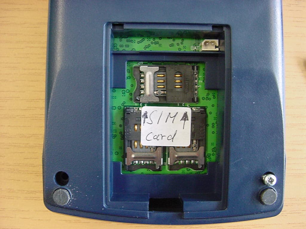
O2SNURIT8320S4
Jul 04, 2005PCS Payment Terminal
Equipment Class
PCB - PCS Licensed Transmitter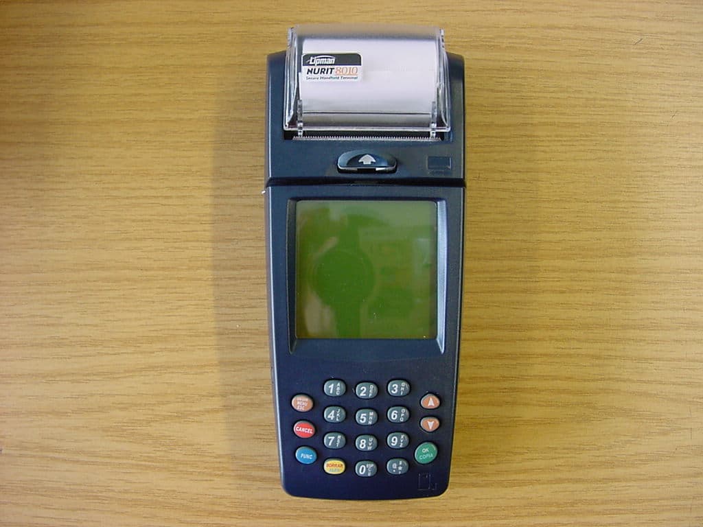
O2SNURIT8000SSG
May 26, 2004PCSPayment Terminal
Equipment Class
PCB - PCS Licensed Transmitter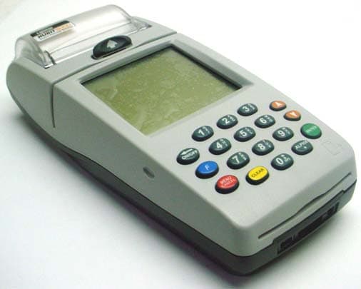
O2SNURIT8000SWD
Apr 04, 2004Hand Held Point of Sale Device
Equipment Class
TNB - Licensed Non-Broadcast Station Transmitter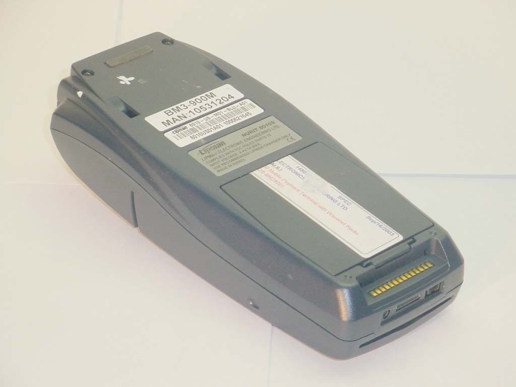
O2SNURIT8000SWM
Feb 12, 2004POINT OF SALE DEVICE
Equipment Class
TNB - Licensed Non-Broadcast Station Transmitter