O2SNURIT3010CTPoint of Sale Device
Verifone Inc.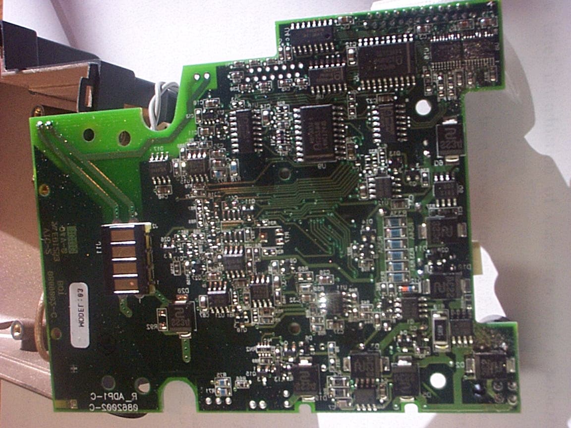
Click to zoom
Application Details
- Equipment Class
- TNB - Licensed Non-Broadcast Station Transmitter
- Date of Grant
- May 31, 2001
- Application Purpose
- Original Equipment
- Date of Application
- Apr 09, 2001
- Equipment Note
- Point of Sale Device
- Frequency Range
- 824.04000000 - 848.97000000
- Company
- Verifone Inc.
- Country
- United States
Documents & Files
Document Text
Text extracted from the exhibit documents filed with the FCC. Open a document above to read the original.
Users Manual
March 2001 APREL Project No.: Consulting * Research * Training * Certification Testing Since 1981 FCC ID: O2SNURIT3010CT Exhibit 9 User’s Manual 082-32-001 NURIT /3010 User Manual1 NURIT 3010 POS/EDC TERMINAL USER MANUAL NURIT 3010 POS/EDC TERMINAL USER MANUAL NOTICEThe information contained in this publication is for informational purposes only and subject to change without notice. It does not represent a commitment on the part of Lipman USA Inc. or Lipman Electronic Engineering Ltd. No part of this publication may be reproduced, transmitted, transcribed, stored in a retrieval system, or translated to any language in any form by any means without the prior written permission of Lipman. Copyright © 1999 by Lipman Electronic Engineering Ltd. All rights reserved. TRADEMARKSTrademarks and trade names contained in this manual belong to their respective companies. LIPMAN USA INC.January 1999 50 Gordon DriveOriginal Syosset, NY 11791Publication No. 082-32-001 Tel: (1) 516-484-9898 Fax: (1) 516-484-9057 E-mail: [email protected] 082-32-001 WARNING Changes or modifications to this unit not expressly approved by the party responsible for compliance could void the user's authority to operate the equipment. FCC compliance statement This equipment has been tested to be found to comply with the limits for class A digital device, pursuant to Part 15 of the FCC Rules. Operation is subject to the following conditions: (1) This device may not cause harmful interference, and (2) this device must accept any interference received, including interference that may cause undesired operation. Class A limits are designed to provide reasonable protection against harmful interference in a residential installation. This equipment generates, uses and can radiate radio frequency energy and, if not installed and used in accordance with the instructions, may cause interference to radio communications. However, there is no guarantee that interference will not occur in a particular installation. If this equipment does cause harmful interference to radio or television reception, which can be determined by turning the equipment off and on, the user is encouraged to try to correct the interference by one or more of the following measures: • Reorient or relocate the receiving antenna. • Increase the separation between the equipment and the receiver. • Connect the equipment into an outlet on a circuit different from that to which the receiver is connected. • Consult your dealer or an experienced technician for help. FCC requirements The Federal Communications Commission (FCC) has established rules permitting this device to be directly connected to the telephone network. Standardized jacks are used for these connections. This equipment should not be used on party or coin lines. If this devise is malfunctioning, it may be causing harm to the telephone network; this devise should be disconnected until the source of the problem can be determined and until repair has been made. If this is not done, the telephone company may temporarily disconnect service. The telephone company may make changes in its technical operations and procedures; if such changes affect the compatibility or use of this devise, the telephone company is required to give adequate notice of the changes. You will be advised to file a complaint with the FCC. If the telephone company requests information on what equipment is connected to their lines, inform them of: One. The telephone number this unit is connected to Two. The ringer equivalence number: 0.3B Three. The USOC jack required: RJ-11C Four. The FCC Registration number: 3D7ISR-25066-DT-E The Ringer Equivalence Number (REN) is used to determine how many devices can be connected to your telephone line. In most areas, the sum of the RENs of all devices on any one line should not exceed five (5). If too many devices are attached, they may not ring properly. FCC Part 15 Requirements Notice • This device must not be installed on coin-operated telephone lines or party lines. • This device (equipment) complies with the requirements in Part 15 of FCC Rules of a Class B computing device. Operation of this device (equipment) is subject to the following two conditions: o This device (equipment) may not cause harmful interference, and o This device (equipment) must accept any interference received, including interference that may cause undesired operation. • If this device (equipment) is used in a residential area, it may cause unacceptable interference to radio and TV reception requiring the operator to take whatever steps necessary to correct the interference. • Repair work on this device (equipment) must by done by Lipman USA, Inc, or an authorized repair station. WARNING: To comply with FCC RF exposure requirements, users must limit device operations to no more than one transaction in any 3 second time period and must keep the device at least 4cm away from bystanders or parts of the user's body other than their hands. 082-32-001 LIPMAN USA - NURIT /3010 Limited Warranty Lipman USA Inc. will repair this product with new or rebuilt parts, free of charge, in the U.S.A. for one (1) year from the date of original purchase in the event of a defect in materials or workmanship. Carry-in or mail-in service in the continental U.S.A. can be obtained during the warranty period from our N.Y. Service Center or call 1-800-4-LIPMAN toll free. In New York State call (516) 484-9898. This warranty is extended only to the original purchaser. A purchase receipt or other proof of date of original purchase will be required in order to exercise your rights under this warranty. This warranty only covers failures due to defects in materials or workmanship which occur during normal use. It does not cover damage which occurs in shipment; failures which are caused by products not supplied by Lipman USA; or failures which result from accident, misuse, abuse, neglect, mishandling, misapplication, alteration or modification; service by an…
Text truncated - open the document above for the full version.
Attestation Statements
March 2001 APREL Project No.: Consulting * Research * Training * Certification Testing Since 1981 FCC ID: O2SNURIT3010CT Exhibit 10 Attestation Statements FCC Part 15, Subpart B Certificate of Conformity FCC Part 2 & 22 Statement of Compliance March 2001 APREL Project No.: Consulting * Research * Training * Certification Testing Since 1981 FCC ID: O2SNURIT3010CT Certificate of Compliance PRODUCT: POINT OF SALE DEVICE MODEL: NURIT 3010 CDPD MANUFACTURER: LIPMAN USA, Inc. We certify that the pertinent tests have been performed on the above described equipment and that this equipment conforms to FCC Parts 2 and 22. See Exhibit 2, Engineering Reports
Cover Letter(s)
March 2001 APREL Project No.: Consulting * Research * Training * Certification Testing Since 1981 FCC ID: O2SNURIT3010CT Table of Contents List of Exhibits Submitted E E X X H H I I B B I I T T 1 1 : : C C O O V V E E R R L L E E T T T T E E R R S S a)Application overview b)Equipment Identification c)Authorization Letter /Agent Designated (Jay Sarkar) d)Request for confidentiality e)Letter from Novatel authorizing to use FCC approved (FCC ID: NBZNRM6832) radio modem in Lipman USA, Inc.’s NURIT 3010 CDPD with Carant Antenna Exhibit 2:Engineering Reports (Test Reports) a)ERP (2.1046) b)Radiated Spurious Emissions (2.1053) c)Bandwidth (2.1049) Bandwidth Limitations (2.1047) d)Spurious Emissions, Antenna Terminal (2.1051) e)Frequency Stability (2.1055) Exhibit 3: Operational/Technical Description Exhibit 4: ID Label/Location Exhibit 5:External Photographs of the Equipment Internal Photographs of the equipment Exhibit 6:Block Diagram (Confidential) Exhibit 7: Schematic Diagram (Confidential) Exhibit 8:Parts List (Confidential), Tune–up Procedure Exhibit 9:User’s Manual Exhibit 10:a) Attestation Statement: FCC Part 15 Declaration of Conformance (DoC) certificate b)Attestation Statement: the equipment complies with Part 2 and 22 Exhibit 11:RF Exposure Information: SAR Report (Includes Test Set-up Photographs)
Cover Letter(s)
March 2001 APREL Project No.: Consulting * Research * Training * Certification Testing Since 1981 FCC ID: O2SNURIT3010CT Exhibit 1 a)Application overview b)Equipment: Rugged handheld computer with integrated wireless communications c)Authorization Letter /Agent Designated (Jay Sarkar) d)Request for confidentiality e)Letter from Novatel Wireless Technologies. authorizing to use FCC approved (FCC ID: NBZNRM-6832) radio modem in Lipman USA, Inc.’s NURIT 3010 CDPD with Carant Antenna March 2001 APREL Project No.: Consulting * Research * Training * Certification Testing Since 1981 EXHIBIT 1b MANUFACTURER: Lipman USA, Inc. FCC ID: O2SNURIT3010CT PRODUCT: Pont of Sale Device MODEL: Nurit 3010 CDPD (with Carant TNC Antenna)) with a Novatel NRM 6832 radio modem (FCC ID:NBZNRM-6832) EUT TYPE: Licensed Non-Broadcast Station Transmitter (TNB) TX Frequency: 824-849 MHz MEASURED ERP:0.141 W
Cover Letter(s)
* Consulting * Research * Training * Certification Testing Since 1981 51 Spectrum Waytel: (613) 820-2730 Nepean, Ontariovisit our Web Pages: www.aprel.comfax: (613) 820-4161 Canada K2R 1E6email: [email protected] May 25, 2001 Mr. Andy Leimer Federal Communications Commission Application Processing Branch 7435 Oakland Mills Road Columbia, Maryland 21046 Re:Question from the FCC FCC ID:O2SNURIT3010CT Correspondence Reference Number:19307 731 Confirmation NumberEA100590 Date of Original E-Mail:May 17, 2001 1:01 PM Dear Mr. Leimer: Pursuant to your e-mail to me, I am forwarding to you our response. The relevant portions of the FCC’s e-mail follow with our response inserted in the appropriate place: To:Jayanta (Jay) Sarkar, null From:Andy Leimer [email protected] FCC Application Processing Branch Re:FCC ID O2SNURIT3010CT Applicant:Lipman USA, Inc Correspondence Reference Number:19307 731 Confirmation Number:EA100590 1)This device uses a Novatel CDPD modem card (EA 92743), which has 600 mW conducted output. There is too much discrepancy between the conducted output and the measured ERP (141 mW). Please explain. Is the difference caused by cable or attenuation between the Novatel card and the antenna or some other reason? * Consulting * Research * Training * Certification Testing Since 1981 51 Spectrum Waytel: (613) 820-2730 Nepean, Ontariovisit our Web Pages: www.aprel.comfax: (613) 820-4161 Canada K2R 1E6email: [email protected] Response:We have re-tested the ERP. Please find below the revised ERP data based on the re-test of the unit. The newly measured ERP is 0.333W.The complete test data for all three channels are shown in the following table. Table 1 Channel No. Nominal Transmit Frequency (MHz) Measured Output Power ERP (Power Level:0) (dBm) ERP (Power Level:0) (W) 991824.0025.230.333 383836.4924.740.298 799849.9025.050.320 Note: Our normal practice in the laboratory is to use a fully charged fresh battery prior to any measurement is carried out. In order to ensure that the process is correct, we measure the battery voltage and the conducted power (if possible) each time the battery is replaced. In this case, the battery was not fully charged as it was discovered while getting ready for re-test. It was the reason for low ERP reported in the submission. However, the SAR measurement is independent of ERP measurement. As such, SAR was measured using fully charged batteries and at full power level. The Table 2 below presents the power (conducted, without the cable loss) for SAR measurement as reported in the SAR report. Table 3 presents the same power level as in Table 2, with the cable loss included in the calculation. It can be seen from the power level in Table 3 that the SAR measurement was performed with a fully charged battery and at full power. A revised summary page of the SAR report is attached with this response. Table No. 2 ScanPower Readings (dBm) TypeHeight (mm)BeforeAfter ∆∆ (dB) Battery # Area2.56.406.050.355 Zoom2.56.306.050.257 Zoom7.56.306.050.253 Zoom12.56.306.020.287 Zoom17.56.306.020.283 Zoom22.56.306.060.244 Depth2.5-22.56.306.010.295 * Consulting * Research * Training * Certification Testing Since 1981 51 Spectrum Waytel: (613) 820-2730 Nepean, Ontariovisit our Web Pages: www.aprel.comfax: (613) 820-4161 Canada K2R 1E6email: [email protected] The following table takes 21 dBm cable losses into account. Table 3 ScanPower Readings (dBm) TypeHeight (mm)BeforeAfter ∆∆ (dB) Battery # Area2.527.4027.050.355 Zoom2.527.3027.050.257 Zoom7.527.3027.050.253 Zoom12.527.3027.020.287 Zoom17.527.3027.020.283 Zoom22.527.3027.060.244 Depth2.5-22.527.3027.010.295 Finally, the discrepancy between the conducted output (27.40 dBm) and the revised ERP (25.23 dBm, 0.333 W) is due to the loss in mismatch between the antenna input and modem output as well as the antenna loss. * Consulting * Research * Training * Certification Testing Since 1981 51 Spectrum Waytel: (613) 820-2730 Nepean, Ontariovisit our Web Pages: www.aprel.comfax: (613) 820-4161 Canada K2R 1E6email: [email protected] 2) Identify the peak SAR location with respect to the device & its antenna on figure 6. Response: Shown below is the peak SAR location with respect to the device and its antenna on figure. The SAR report has been modified to reflect this. In addition, the summary page of the SAR report has been modified showing the ERP. A copy the same page is attached with this. I trust that the above will answer your inquiry. If not, please feel free to contact me. Regards, Jayanta (Jay) K.Sarkar Director Technical Director, Standards and Certification Attachment: SAR summary page -5-4-3-2-1012345678910111213 14 15 16 17 18 19 20 21 x-axis (cm) y-axis (cm) Local SAR (W/kg) 4-4.5 3.5-4 3-3.5 2.5-3 2-2.5 1.5-2 1-1.5 0.5-1 0-0.5 * Consulting * Research * Training * Certification Testing Since 1981 51 Spectrum Waytel: (613) 820-2730 Nepean, Ontariovisit our Web Pages: www.aprel.comfax: (613) 820-4161 Canada K2R 1E6email: [email protected] Attachment: FCC ID: O2SNURIT3010CT Applicant:Lipman Equipment:Point of Sale Device with a Novatel NRM-6832 Wireless Modem Model:Nurit 3010, CDPD Standard:FCC 96 –326, Guidelines for Evaluating the Environmental Effects of Radio-Frequency Radiation ENGINEERING SUMMARY This report contains the results of the engineering evaluation performed on a Nurit 3010 POS EDC Terminal which incorporates a Novatel NRM-6832 CDPD modem and has a detachable Carant 3664 antenna. The measurements were carried out in accordance with FCC 96-326. The Nurit 3010 was evaluated for its maximum power level 0.333W(ERP). The duty factor of the radio modem is 100 %. The Nurit 3010 was tested at low, middle, and high channels for the keyboard up, keyboard down, left, and right sides with the antenna in the 0, 90, and 180 degree positions. The maximum 10g SAR ( 2.65 W/kg) was found to coincide with the peak performance RF output power of channel 383 (836.49 MHz) for the left side of the device with the antenna in the 90 degree position. (The hot s…
Text truncated - open the document above for the full version.
External Photos
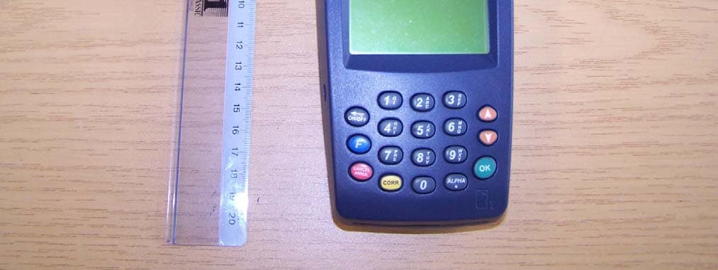
March 2001 APREL Project No.: Consulting * Research * Training * Certification Testing Since 1981 FCC ID: O2SNURIT3010CT Exhibit 5 Photographs of the Equipment External Photos Internal Photos
ID Label/Location Info
March 2001 APREL Project No.: Consulting * Research * Training * Certification Testing Since 1981 FCC ID: O2SNURIT3010CT Exhibit 4 FCC ID Label/Location
ID Label/Location Info
March 2001 APREL Project No.: Consulting * Research * Training * Certification Testing Since 1981 FCC ID: O2SNURIT3010CT Exhibit 4 FCC ID Label/Location
RF Exposure Info
March 2001 APREL Project No.: Consulting * Research * Training * Certification Testing Since 1981 FCC ID: O2SNURIT3010CT Exhibit 11 RF Exposure Information Sar Report Page 2 of 17 Project #: «Project» 51 Spectrum WayTel. (613) 820-2730 Nepean, Ontario, K2R 1E6 Fax (613) 820 4161 e-mail: [email protected] © APREL 2000 This report shall not be reproduced, except in full, without the express written approval of APREL Laboratories. FCC ID:O2SNURIT3010CT Applicant:Lipman Equipment:Point of Sale Device with a Novatel NRM-6832 Wireless Modem Model:Nurit 3010, CDPD Standard:FCC 96 –326, Guidelines for Evaluating the Environmental Effects of Radio- Frequency Radiation ENGINEERING SUMMARY This report contains the results of the engineering evaluation performed on a Nurit 3010 POS EDC Terminal which incorporates a Novatel NRM-6832 CDPD modem and has a detachable Carant 3664 antenna. The measurements were carried out in accordance with FCC 96-326. The Nurit 3010 was evaluated for its maximum power level 0.141W(ERP). The duty factor of the radio modem is 100 %. The Nurit 3010 was tested at low, middle, and high channels for the keyboard up, keyboard down, left, and right sides with the antenna in the 0, 90, and 180 degree positions. The maximum 10g SAR ( 2.65 W/kg) was found to coincide with the peak performance RF output power of channel 383 (836.49 MHz) for the left side of the device with the antenna in the 90 degree position. (The hot spot is located on the antenna). Test data and graphs are presented in this report. At a separation distance of 4 cm from the antenna of the device, the maximum 1g SAR is 0.10 W/kg. The manual will have a warning to keep bystanders, and parts of the user’s body other than extremities, at least 4 cm away from the antenna. Based on the test results and on how the device will be marketed and used, it is certified that the product meets the requirements as set forth in the above specifications, for RF exposure environment. (The results presented in this report relate only to the sample tested.) Page 3 of 17 Project #: «Project» 51 Spectrum WayTel. (613) 820-2730 Nepean, Ontario, K2R 1E6 Fax (613) 820 4161 e-mail: [email protected] © APREL 2000 This report shall not be reproduced, except in full, without the express written approval of APREL Laboratories. TABLE OF CONTENTS 1.Introduction....................................................................................................................4 2.Applicable Documents...................................................................................................4 3.Device Under Investigation...........................................................................................4 4.Test Equipment..............................................................................................................5 5.Test Methodology..........................................................................................................5 6.Test Results....................................................................................................................6 6.1.Transmitter Characteristics............................................................................................6 6.2.SAR Measurements........................................................................................................7 7.User’s Hand Exposure...................................................................................................8 8.Bystander Exposure......................................................................................................9 9.Conclusions..................................................................................................................11 APPENDIX A. Measurement Setup, Tissue Properties and SAR Graphs.............................12 APPENDIX B. Uncertainty Budget........................................................................................14 APPENDIX C. Validation Scan on a Flat Phantom................................................................15 APPENDIX D. Probe Calibration...........................................................................................17 TABLES AND FIGURES Table 1. Sampled RF Power.....................................................................................................6 Table 2. SAR Measurements.....................................................................................................8 Table 3. SAR versus DUI-Phantom Separation......................................................................10 Figure 1. Setup Figure 2. Setup Closeup...........................................................................12 Figure 3. Antenna in 0 Degree Position ..................................................................................12 Figure 4. Antenna in 90 Degree Position.................................................................................12 Figure 5. Antenna in 180 Degree Position...............................................................................12 Table 4. Dielectric Properties of the Simulated Muscle Tissue at 835 MHz..........................13 Figure 6. Contour Plot of the Area Scan 2.5mm Above Phantom Surface..............................13 Figure 7. Surface Plot of the Area Scan 2.5mm Above Phantom Surface...............................14 Table 5. Uncertainty Budget...................................................................................................14 Figure 8. Contour Plot of the Reference Area Scan 2.5mm Above Phantom..........................15 Figure 9. Surface Plot of the Reference Area Scan 2.5mm Above Phantom...........................15 Figure 10. Peak Local SAR versus Separation (1 gram SAR).................................................16 Page 4 of 17 Project #: «Project» 51 Spectrum WayTel. (613) 820-2730 Nepean, Ontario, K2R 1E6 Fax (613) 820 4161 e-mail: [email protected] © APREL 2000 This report shall not be reproduced, except in full, without the express…
Text truncated - open the document above for the full version.
RF Exposure Info
Spectrum Sciences Institute RF Dosimetry Research Board Attention: all comments, suggestions, and inquiries should be addressed to Dr. Jack J. Wojcik or Dr. Paul G. Cardinal 51 Spectrum Way, Nepean, Ontario, K2R 1E6, Canada. tel.:(613)820-2730, fax:(613)820-4161 e-mail: [email protected] Phantom Design Requirements SSI/DRB-TP-D01-031 PART of SAR Measurements Requirements SSI/DRB-TP-D01-030 DRAFT Prepared jointly with: Near Field Measurements Laboratory March 1998 - NOTICE - This draft was prepared to assist the Dosimetry Research Board of SPECTRUM SCIENCES INSTITUTE and specifically the Working Group on SAR Measurements. It is submitted as a basis for discussion only, and is not binding on APREL Inc. Subsequent study may lead to revisions of the document, both in numerical values and/or form, and after continuing study and analysis, APREL Inc. specifically reserves the right to add to, or amend the content of this contribution. SSI/DRB-TP-D01-031 Page 2 of 15 Comments and inquiries should be addressed to:Ref: Project U404-7-0016 -1997 RF Dosimetry Research Board (DRB) Spectrum Sciences Institute 51 Spectrum Way, Nepean, Ontario, Canada K2R 1E6 Tel. (613) 820-6471 Fax (613) 820-4161 e-mail: [email protected] Spectrum Sciences Institute RF Dosimetry Research Board TABLE OF CONTENTS 1.0Introduction3 1.1Purpose And Scope Of The Standard3 1.2Test Facilities3 1.3Test Personnel3 1.4Standard Environmental Conditions3 2.0Background4 3.0References5 4.0Definitions6 5.0Phantoms6 5.1Universal Head-Arm (Unihead) Phantom6 5.1.1Head Simulator6 5.1.2Arm And Hand Simulator10 5.1.3Materials10 5.2Flat Phantom13 5.3Insulated Flat Phantom13 6.0Sar Laboratory Setup13 7.0Test configurations using the Uni-Head15 SSI/DRB-TP-D01-031 Page 3 of 15 Comments and inquiries should be addressed to:Ref: Project U404-7-0016 -1997 RF Dosimetry Research Board (DRB) Spectrum Sciences Institute 51 Spectrum Way, Nepean, Ontario, Canada K2R 1E6 Tel. (613) 820-6471 Fax (613) 820-4161 e-mail: [email protected] Spectrum Sciences Institute RF Dosimetry Research Board 1.0INTRODUCTION 1.1Purpose and Scope of the Standard The purpose of this document is to standardize the phantom(s) required for Specific Absorption Rate (SAR) testing associated with SAR measuring systems. This document defines the parts and dimensions of the phantom, in accordance with industry standards and practices. This Standard defines: - the methodology and procedures used to define a reproducible representation of the human head, hand and arm - the dimensions on the canonical shapes used, and the materials required - the hardware required and the proper setup This Standard is part of a Certification Program Methodology as described in a separate document entitled "SSI/DBR TP-D01-030, Specific Absorption Rate (SAR) Standard For Portable Telecommunications Devices, March 1998". SSI/DBR TP-D01-031 contains specific criteria that must be met for SAR certification. 1.2Test Facilities All calibration work as described in this Standard shall be performed at an ISO/IEC Guide 25 accredited laboratory. 1.3Test Personnel Personnel performing the calibration will be experienced in relevant measurements (e.g. physical properties or RF characteristics) and supervised by a person proficient in SAR measurements. 1.4Standard Environmental Conditions All measurements and calibration should be performed under normal laboratory conditions for physical properties and electrical characteristics as stipulated by ISO/IEC Guide 25. The nominal temperature for physical property measurements and for electrical characterization are 20°C and 23°C, respectively. SSI/DRB-TP-D01-031 Page 4 of 15 Comments and inquiries should be addressed to:Ref: Project U404-7-0016 -1997 RF Dosimetry Research Board (DRB) Spectrum Sciences Institute 51 Spectrum Way, Nepean, Ontario, Canada K2R 1E6 Tel. (613) 820-6471 Fax (613) 820-4161 e-mail: [email protected] Spectrum Sciences Institute RF Dosimetry Research Board 2.0BACKGROUND Portable communication devices used by consumers typically operate over the range of several watts to a milliwatt, or less, using either analog or digital modulation techniques. Most portable telephones have antennas that radiate within a few centimeters of the user's head. The field strength and field distribution near the antenna are highly dependent on the location, orientation and electromagnetic characteristics of adjacent objects. The head and hand are normally in the reactive near-field region of the antenna where the electromagnetic field is non-propagating. The energy absorbed in the head and hand is mainly due to electric fields induced by the magnetic fields generated by currents flowing through the feedpoint, along the antenna and body of the portable device. The RF energy is scattered and attenuated as it propagates through the tissues of the head, and maximum energy absorption is expected in the more absorptive high water-content tissues near the surface of the head or hand. To account for near-field effects portable devices are evaluated with realistic head models called a phantom. A phantom is a device that simulates the size, contours, and electrical characteristics of human tissue at normal body temperature. It is composed of a manikin (solid shell) and a tissue-equivalent synthetic material solution (see SSI/DRB-TP-D01-033). The solid manikin shell is made of a dielectric material, which is transparent to RF energy (i.e. has very low RF absorption), and is as thin as possible while maintaining the strength necessary to hold the mass of simulated tissue. Current phantoms in use are: - Universal Head-arm (UniHead) Phantom for ear independent evaluation of the RF exposure in the head of users by telephone-type devices, as well as RF exposure in the head of users of hand held radios positioned in front of the face, and in the hand of users of hand held portable devices - Flat Phantom for evaluating the RF exposure of other part…
Text truncated - open the document above for the full version.
Test Report
March 2001 APREL Project No.: Consulting * Research * Training * Certification Testing Since 1981 FCC ID: O2SNURIT3010CT Exhibit 2a Engineering Report on ERP (2.1046) Assessment of Compliance for Measurement of Effective Radiated Power (ERP)in accordance with the FCC Rules & Regulations Part 2.1046 & 22 Point of Sale Device Nurit 3010 with a Novatel Wireless CDPD radio transmitter and TNC Carant Antenna Lipman USA, Inc. 51 Spectrum Way Nepean ON K2R 1E6 Tel: (613) 820-2730 Fax: (613) 820-4161 email: [email protected] March 2001 LPMB-NURIT3010-POS-EDC Terminal w. Novatel CDPD-3684 This report shall not be reproduced, except in full, without the express written approval of APREL Laboratories March 2001 Page 2 APREL Project No LPMB-Nurit 3010 POS EDC Terminal w. Novatel CDPD-3684 This report shall not be reproduced, except in full, without the express written approval of APREL Laboratories Consulting * Research * Training * Certification Testing Since 1981 FCC ID:O2SNURIT3010CT Applicant:Lipman USA, Inc. Equipment:Point of Sale Device Model:Nurit 3010 CDPD with a Novatel NRM-6832 transmitter, CDPD Standard:FCC Rules and Regulations Part 2.1046 & 22 ENGINEERING SUMMARY This report contains the results of the effective radiated power (ERP) measurement performed on a LIPMAN Point of Sale Device operating with a built-in Novatel NRM-6832 radio transmitter equipped with a detachable Carant 3664 antenna. The measurements were carried out in accordance with the FCC Rules and Regulations Part 2.1046 and 22. Tests were conducted to determine the peak ERP of the above sample. Nurit 3010 CDPD was tested for ERP at high, middle, and low frequencies with the maximum ERP obtained at channel No.: 799 with the frequency being 848.97 MHz. The test data is presented in page 10 of this report. The measured ERP is 0.141 W. (The results presented in this report relate only to the sample tested.) March 2001 Page 3 APREL Project No LPMB-Nurit 3010 POS EDC Terminal w. Novatel CDPD-3684 This report shall not be reproduced, except in full, without the express written approval of APREL Laboratories Consulting * Research * Training * Certification Testing Since 1981 INTRODUCTION General This report describes the results of the effective radiated power (ERP) measurement conducted on a Lipman USA Point of Sale Device model Nurit 3010 CDPD operating with a built-in Novatel NRM- 6832 radio transmitter, and equipped with a Carant 3664 antenna having a TNC male type connector that bolts through the casing of the unit. Tests were performed to determine the peak ERP for the above sample. Test Facility The tests were perfor…
Text truncated - open the document above for the full version.
Contact Information
Applicant
Andrey Glemb(Certificate Engineer)
Technical Contact
Non-Technical Contact
Lipman USA, Inc.John R Carpino
[email protected]516-484-9898
Test Firm
APREL LaboratoriesJay Sarkar
Technical Specifications
| # | Rule Parts | Frequency Range | Power Output | Emission | Tolerance |
|---|---|---|---|---|---|
| 1 | 22.901(d) | 824.04 MHz - 848.97 MHz | 333.00 mW | 28K8FXW | 2.5000000000 ppm |
Other Applications from Verifone Inc.
O2SNURIT8000SSQ
Dec 12, 2005Hand held Payment Terminal
Equipment Class
PCB - PCS Licensed Transmitter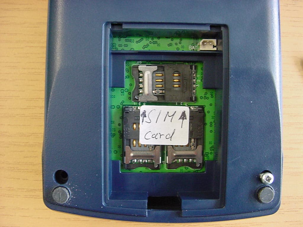
O2SNURIT8320S4
Jul 04, 2005PCS Payment Terminal
Equipment Class
PCB - PCS Licensed Transmitter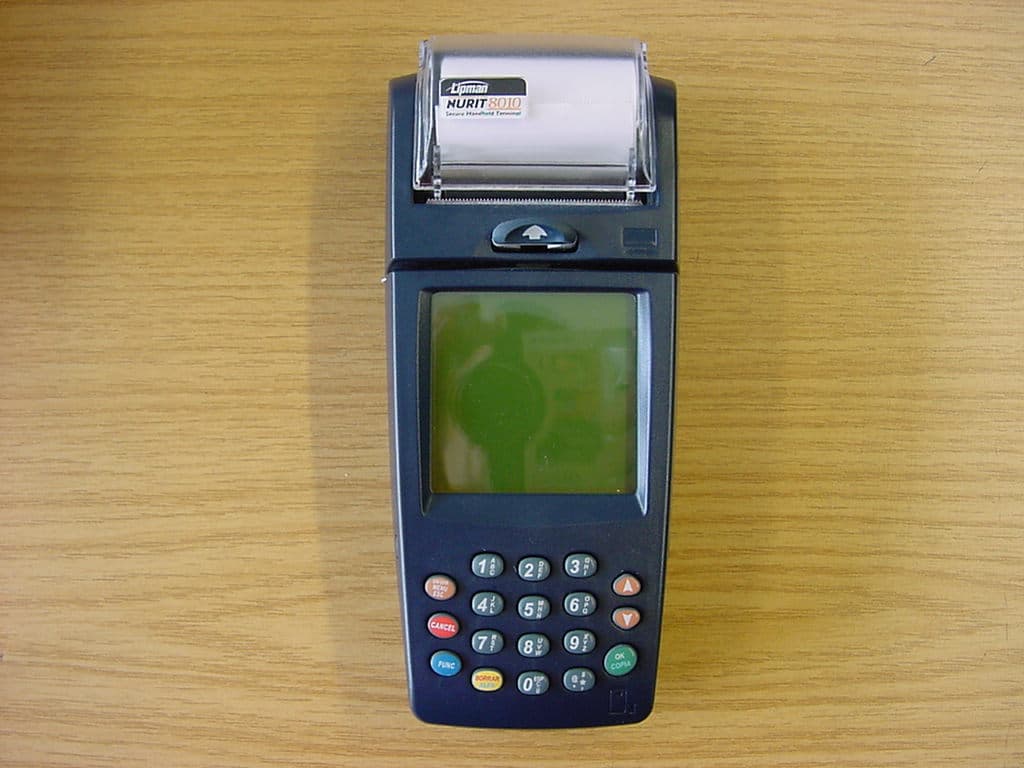
O2SNURIT8000SSG
May 26, 2004PCSPayment Terminal
Equipment Class
PCB - PCS Licensed Transmitter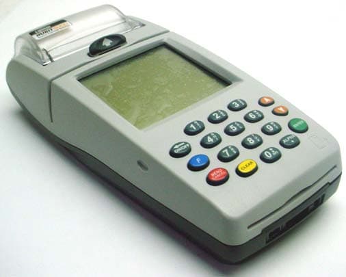
O2SNURIT8000SWD
Apr 04, 2004Hand Held Point of Sale Device
Equipment Class
TNB - Licensed Non-Broadcast Station Transmitter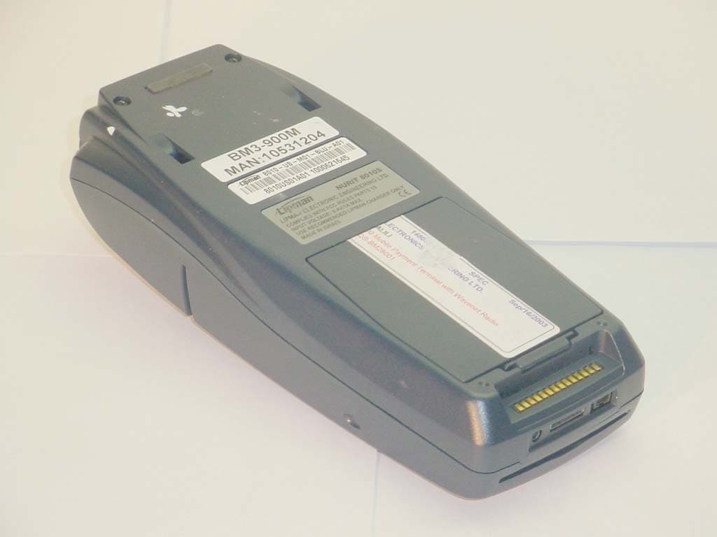
O2SNURIT8000SWM
Feb 12, 2004POINT OF SALE DEVICE
Equipment Class
TNB - Licensed Non-Broadcast Station Transmitter