O4X5-ALA00125ELPAS LF BUS READER
Elpas Solutions Ltd.
Click to zoom
Application Details
- Equipment Class
- DCD - Part 15 Low Power Transmitter Below 1705 kHz
- Date of Grant
- Apr 18, 2013
- Application Purpose
- Original Equipment
- Date of Application
- Apr 18, 2013
- Equipment Note
- ELPAS LF BUS READER
- Frequency Range
- 0.12500000 - 0.12500000
- Company
- Elpas Solutions Ltd.
- Country
- Israel
Documents & Files
Document Text
Text extracted from the exhibit documents filed with the FCC. Open a document above to read the original.
Users Manual
www.elpas.com Page 1 of 7 V22/Jan 2013 Elpas LF BUS Beacon For P/Ns: 5-ALA00125-11, 5-ALA00125-12 & 5-ALA00125-2 Installation Guide Introduction This installation guide provides basic instructions for common LF BUS Beacon installation scenarios. CAUTION! It is important that you read, understand, and follow the instructions in this document. If you have questions, call your local Elpas support representative. Product Description The Elpas LF BUS Beacon is a fully supervised, 125KHz emitter that adds instantaneous location (choke-point) awareness to RTLS security and safety applications The LF BUS Beacon generates a user-adjustable, spherical shaped electromagnetic field up to 1.5m/5ft in radius that can be used to cover a single interior doorway. Optionally, up to four LF BUS Beacons can be deployed in ‘Primary–Secondary’ star or daisy-chain topologies to cover large double-doors or architectural complex indoor entrance/exit areas The LF BUS Beacon also contains an I/O port that enables the monitoring of one alarm sensor and control of either one digital open-collector output or one 26-bit Wiegand device Note: An Elpas RS-485 BUS may contain up to fifteen Elpas BUS devices (such as RF or IR Readers, Elpas Display Panels, LF Beacons or other Primary BUS Beacons) which are wired together using Elpas RS-485 Junction Boxes (P/N:5-JBA00485). LF BUS Beacon (Primary) - Sample Network Topology Primary/Secondary Beacons – Front View Front Cover Tamper Switch: All BUS beacons contain a tamper switch which indicates non-authorized attempts to remove the device’s front cover when in operation. The tamper switch is also used to control the coverage area of the LF field. (See page 4 for details.) Status LED: All BUS beacons contain a Red, Green and Orange LED array that detail the status of the devices: Green LED o Unregistered: Flashes once/second o Power up/Communication Loss/Sync Cable Disconnected: Flashes once/second Red LED o Invalid ID: Flashes once/second - See page 4 for additional details o Device Tamper: Flashes once/second o Output Activated: Flashes once Orange LED o Flashes to indicate the selected LF field range - See page 5 for additional details DIP Switch: Only the Primary Beacon has an eight-position DIP Switch for assigning its ID Address. (See page 4 for details.) Primary/Secondary Beacons – Rear View Rear Cover Tamper Switch: All BUS Beacons contain a dual purpose tamper switch which indicates non-authorized attempts to remove the device’s rear cover when in operation. RS-485 Interface: All BUS beacons contain a female RJ-11 connector for linking to the RS-485 Junction Box. This connector is used for both power & data. (See page 2 for details) Buzzer: The beacon has a buzzer that sounds when an improper ID Address has been assigned. (See page 4 for details.) General Purpose Inputs: All BUS Beacons have general purpose inputs. (See page 6 for details.) Digital Output: The primary beacon and the secondary beacon have one digital output. (See page 6 for details.) LF BUS Beacon (Front View-Cover Removed) LF BUS Beacon (Rear View) IMPORTANT: BUS Beacons MUST BE powered-down while wiring the unit’s I/Os and when connecting to the RS-485 BUS. This will prevent accidental shorts/spikes to cause damage to the devices LF BUS Beacon – Installation Guide www.elpas.com Page 2 of 7 V22/Jan 2013 RS-485 BUS/Stub Topology The RS-485 BUS MUST BE wired using a BUS/Stub topology where the BUS Master (a RF IP Reader or an ELC Controller) is connected anywhere along the BUS. The topology supports data transmission between the BUS Master and up to 15 Elpas BUS Devices (such as RF or IR Readers; LF Beacons primary & secondary), Elpas Display Panels and 6x6 I/O Modules using Elpas RS-485 Junction Boxes (P/N: 5-JBA00485). IMPORTANT NOTE: Only 1 RF IP Reader/ELC Controller and up to 7 RF BUS Readers may coexist together on a single BUS. 200M/650Ft: Max. BUS length 10M/30Ft: Max. Stub length 100 Ohm Termination: Required each end of the BUS. Recommended RS-485 Backbone Cable Type: CAT5 Solid (4x2x26AWG) For Power: Use three-twisted pairs (six conductors) between RS-485 Junction Boxes For Data: Use one-twisted pair (two conductors) between RS-485 Junction Boxes Primary/Secondary Synchronization Up to four LF BUS Beacons can be deployed in ‘Primary–Secondary’ Daisy-Chain or Star Topologies in order to cover large double-doors or architectural complex indoor entrance/exit areas. When deploying either of these two topologies, the LF fields generated by the secondary beacons MUST BE synchronized to pulse at precisely the same moment in time as the LF field generated by the primary unit in order to avoid mutual interference between any of the LF fields. To implement Primary/Secondary Synchronization a Sync Data Link (typically using a 2x2x26 Category 5 cable) needs to be physically connected between the Primary Beacon and all of the Secondary devices. LF BUS Beacon – Installation Guide www.elpas.com Page 3 of 7 V22/Jan 2013 Primary/Secondary Synch Data Connection Diagram – Daisy-Chain Topology Primary/Secondary Synch Data Connection Diagram – Star Topology LF BUS Beacon – Installation Guide www.elpas.com Page 4 of 7 V22/Jan 2013 ID Address Setup Before initial power-up, the Primary LF BUS Beacon must be assigned a unique ID Address (Neuron ID) in order for the Eiris Software Platform or an Elpas Local Controller to be able to identify the device. Convert the Neuron ID (typically using a scientific calculator) into the two- digit hexadecimal number that correctly corresponds to the DIP switch found on the LF Beacon. This hexadecimal number will be used to register the beacon’s ID address into the EIRIS or the ELC database. NOTE: It is vital that a newly assigned ID Address does not conflict with any other ID Address that has already been assigned to any other beacon. The following Neuron ID Addresses SHOULD NOT BE ASSIGNED to the Primary LF BUS Beacon: 0x00 (00000000), 0x13 (00000000), 0x35 (00000000), 0x4B …
Text truncated - open the document above for the full version.
Operational Description
Product Description The Elpas LF BUS Exciter is a supervised 125KHz field emitter. The device is used for adding real-time location visibility to Elpas RTLS Security, Safety & Visibility solutions or 3rd party healthcare management systems. The LF BUS Exciter is easily attached to either solid or hollow walls and is designed to generate a continuous, user-adjustable, electromagnetic, spherical shaped field up to 1.5m/5ft in radius that can be used to cover a single interior doorway. Optionally, up to four LF BUS Exciters can be deployed in ‘Primary–Secondary’ star or daisy-chain topologies to cover large double-doors or architectural complex indoor entrance/exit areas. Should an individual or asset bearing an Elpas Active RFID Tag enter the exciter’s electromagnetic field; the tag is prompted to transmit a message indicating its presence at this location. The messages are received by nearby Elpas RF IP/BUS Readers or by Elpas Local Controllers and can either be locally processed or relayed over wired or wireless Ethernet/Wi-Fi networks to a RTLS host application such as Eiris Enterprise Software for triggering location alerts or for identifying the tag’s precise location and status. The LF BUS Exciter also contains an I/O port that enables the monitoring of one alarm sensor and control of either one digital open open collector output or one 26-bit Wiegand device. Technology Low frequency electromagnetic spherical shaped field (125 KHz) *Output Ranges Primary: Four user selectable ranges: From 10cm/4.0 inches to 1.5m/5ft radius Secondary: Two user selectable ranges: From 1.0m/3.3ft to 1.5m/5ft radius Transmission Rate Continuous bursts of LF transmissions (each about 12 ms in duration) Output and Format 3-byte messages (preamble, exciter ID and CRC) Output Power Less than 60 dbμv at 1.5m/5ft Output Bit Rate 2,000 bit per second
Test Report
Test Report E102000.00 Elpas Solutions Ltd. Page 1 of 23 FCC ACC M Ver 1.1 05Mayl 2000 DATE: 19 March 2013 I.T.L. (PRODUCT TESTING) LTD. FCC Radio Test Report for Elpas Solutions Ltd.* Equipment under test: Elpas LF BUS Reader 5- ALA000125-12* * See customer’s letters/declaration on pages 5-6. Written by: _____________________________ D. Shidlowsky, Documentation Approved by: ______________________________ A. Sharabi, Test Engineer Approved by: _____________________________ I. Raz, EMC Laboratory Manager This report must not be reproduced, except in full, without the written permission of I.T.L. (Product Testing) Ltd. This report relates only to items tested. Test Report E102000.00 Elpas Solutions Ltd. Page 2 of 23 FCC ACC M Ver 1.1 05Mayl 2000 Measurement/Technical Report for Elpas Solutions Ltd. Elpas LF BUS Reader 5-ALA000125-12 FCC ID: O4X5-ALA00125 IC: 1467G-5ALA00125 This report concerns: Original Grant: X Class I change: Class II change: Equipment type: Part 15 Low Power Transmitter Below 1705 kHz 47CFR15 Section 15.205; 15.209 Application for Certification Applicant for this device: prepared by: (different from "prepared by") Ishaishou Raz Meir Erenkrantz ITL (Product Testing) Ltd. Elpas Solutions Ltd. Kfar Bin Nun 30 Habarzel Street D.N. Shimshon 99780 Tel-Aviv 69710 Israel Israel e-mail [email protected] Tel: +972-3 -768-1410 Fax: +972-3- 768-1415 e-mail: [email protected] Test Report E102000.00 Elpas Solutions Ltd. Page 3 of 23 FCC ACC M Ver 1.1 05Mayl 2000 TABLE OF CONTENTS 1. GENERAL INFORMATION ------------------------------------------------------------------------------- 4 1.1 Administrative Information ................................................................................. 4 1.2 List of Accreditations ......................................................................................... 7 1.3 Product Description ........................................................................................... 8 1.4 Test Methodology .............................................................................................. 8 1.5 Test Facility ....................................................................................................... 8 1.6 Measurement Uncertainty ................................................................................. 8 2. SYSTEM TEST CONFIGURATION --------------------------------------------------------------------- 9 2.1 Justification ........................................................................................................ 9 2.2 EUT Exercise Software ..................................................................................... 9 2.3 Special Accessories .......................................................................................... 9 2.4 Equipment Modifications ................................................................................... 9 2.5 Configuration of Tested System ........................................................................ 9 3. TEST SET-UP PHOTO ------------------------------------------------------------------------------------10 4. AVERAGE FACTOR CALCULATION ----------------------------------------------------------------11 5. FIELD STRENGTH OF FUNDAMENTAL 125 KHZ TRANSMITTER -------------------------12 5.1 Test Specification ............................................................................................ 12 5.2 Test Procedure ................................................................................................ 12 5.3 Test Results .................................................................................................... 12 5.4 Test Instrumentation Used, Field Strength of Fundamental ........................... 15 5.1 Field Strength Calculation ............................................................................... 15 6. RADIATED EMISSION, 9 KHZ – 30 MHZ -----------------------------------------------------------16 6.1 Test Specification ............................................................................................ 16 6.2 Test Procedure ................................................................................................ 16 6.3 Test results ...................................................................................................... 16 6.4 Test Instrumentation Used, Radiated Measurements .................................... 18 6.5 Field Strength Calculation ............................................................................... 18 7. BANDWIDTH ------------------------------------------------------------------------------------------------19 7.1 Test Procedure ................................................................................................ 19 7.2 Test Results .................................................................................................... 19 7.3 Test Instrumentation Used, Radiated Measurements .................................... 20 8. APPENDIX A - CORRECTION FACTORS ----------------------------------------------------------21 8.1 Correction factors for CABLE ......................................................................... 21 8.2 Correction factors for PASSIVE LOOP ANTENNA ........................................ 22 9. COMPARISON REQUIREMENTS FCC WITH INDUSTRY CANADA ------------------------23 Test Report E102000.00 Elpas Solutions Ltd. Page 4 of 23 FCC ACC M Ver 1.1 05Mayl 2000 1. General Information 1.1 Administrative Information Manufacturer: Elpas Solutions Ltd.* Manufacturer's Address: P.O.B. 13132 30 Habarzel St. Tel Aviv 69710 Israel Tel: +972-03-7681400 Fax: +972-03-7681415 Manufacturer's Representative: Avi Manela Equipment Under Test (E.U.T): Elpas LF BUS Reader Equipment Model No.: 5-ALA000125-12 ** Equipment Serial No.: Not Designated Date of Receipt of E.U.T: 13.12.10 Start of Test: 13.12.10 End of Test: 14.12.10 Test Laboratory Location: I.T.L (Product Testing) Ltd. Kfar Bin Nun, ISRAEL 99780 Test Specifications: FCC Part…
Text truncated - open the document above for the full version.
Contact Information
Applicant
Arick Elshtein(International Compliance Manager)
Test Firm
Israel Testing LaboratoriesIIan Cohen
Technical Specifications
| # | Rule Parts | Frequency Range | Power Output |
|---|---|---|---|
| 1 | 15C | 0.125 MHz - 0.125 MHz | - |
Other Applications from Elpas Solutions Ltd.
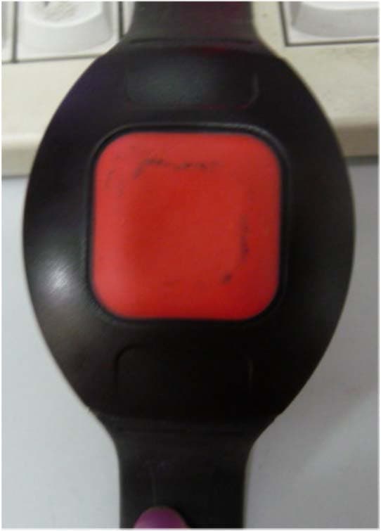
O4X5-WTG411210
Aug 27, 2015Quad Technology Wrist Tag
Equipment Class
DCD - Part 15 Low Power Transmitter Below 1705 kHz
O4X5-LW2410370
Apr 27, 2015Lone Worker Active RFID Tag
Equipment Class
DSR - Part 15 Remote Control/Security Device Transceiver
O4X5-LCA004331
Apr 01, 2015Enhanced Local Controller
Equipment Class
DSR - Part 15 Remote Control/Security Device Transceiver
O4X5-ALC01121-0
Mar 17, 2015ALC LF BUS Beacon, indoor/outdoor 125 kHz + 433 MHz
Equipment Class
DSR - Part 15 Remote Control/Security Device Transceiver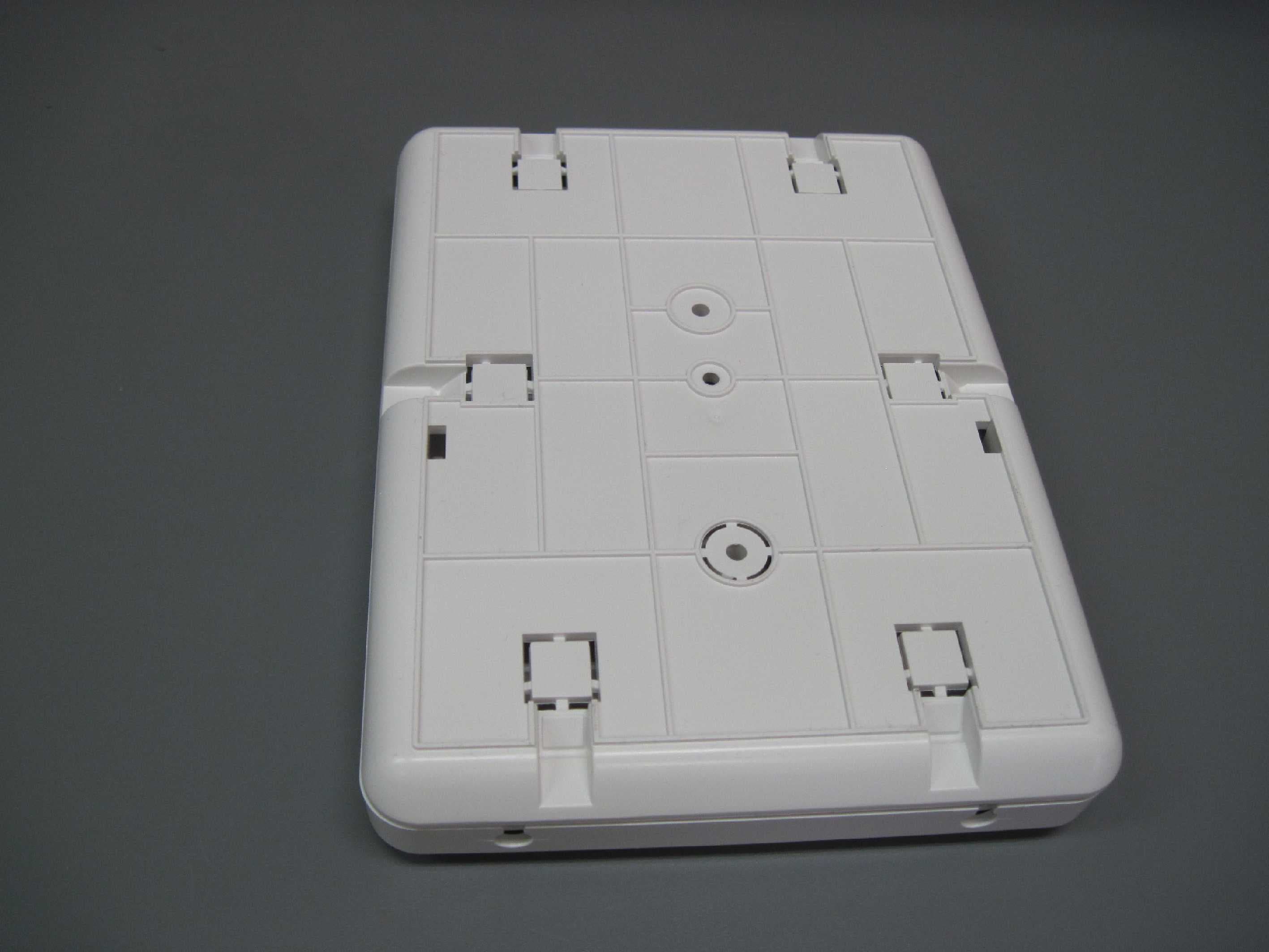
O4X5-ALC01021-0
Feb 11, 2015ALC LF BUS Beacon 5-ALC01021-0, 5-ALC11021-0
Equipment Class
DCD - Part 15 Low Power Transmitter Below 1705 kHz