O4X5-ALC01021-0ALC LF BUS Beacon 5-ALC01021-0, 5-ALC11021-0
Elpas Solutions Ltd.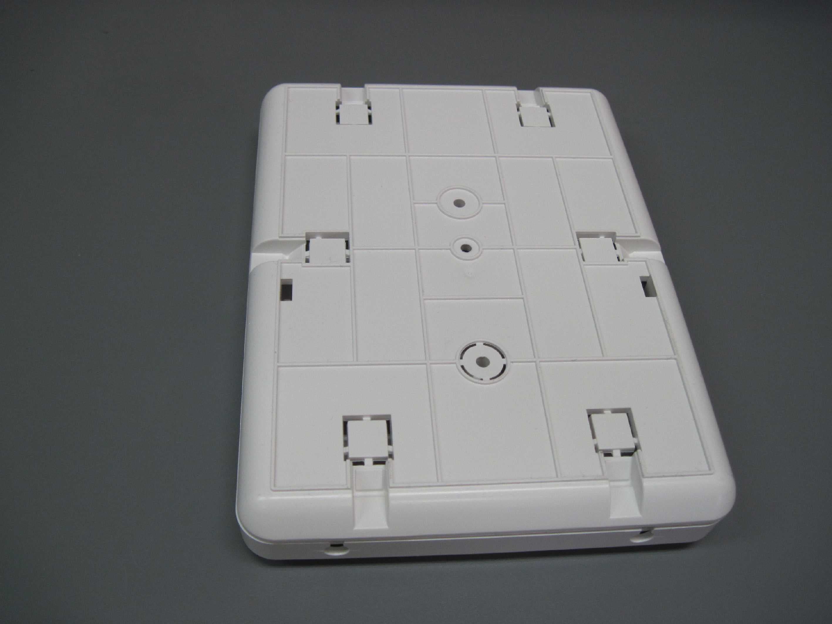
Click to zoom
Application Details
- Equipment Class
- DCD - Part 15 Low Power Transmitter Below 1705 kHz
- Date of Grant
- Feb 11, 2015
- Application Purpose
- Original Equipment
- Date of Application
- Feb 11, 2015
- Equipment Note
- ALC LF BUS Beacon 5-ALC01021-0, 5-ALC11021-0
- Frequency Range
- 0.12500000 - 0.12500000
- Company
- Elpas Solutions Ltd.
- Country
- Israel
Documents & Files
Document Text
Text extracted from the exhibit documents filed with the FCC. Open a document above to read the original.
Users Manual
www.elpas.com Page 1 of 12 V2/Dec 2014 ALC Indoor LF BUS Beacon For P/N: 5-ALC01021-0 (no RF), 5-ALC01121-0 (RF) Installation Guide Introduction This installation guide provides basic instructions for common ALC LF BUS Beacon installation scenarios. CAUTION! It is important that you read and follow the instructions in this document. If you have questions, call your local Elpas support representative. Reasonable effort was made to ensure that the specifications and other information in this guide are accurate and complete at the time of its publication. Nonetheless, all information contained in this document is subject to change at any time without prior notice. Any modifications to this equipment without prior written consent of Elpas Solutions Ltd. will void all warranties including the pertinent regulatory certifications and as such revoke your authority to operate this product. Furthermore unauthorized modifications may also result in damage to this device and may cause a safety hazard to the users. Product Description The Elpas ALC LF BUS Beacon is a 125KHz emitter that adds instantaneous location, choke-point (a door or any other opening that controls ingress and egress from a protected area), awareness to RTLS security, and safety applications. 5-ALC01121-0 is also fully supervised. The ALC LF BUS Beacon generates a user-adjustable, elliptically shaped field up to 4m/13ft (perpendicular to the device) and 3.5m/11.5ft (parallel to the device) in radius that can be used to cover a single interior doorway. Optionally, up to three ALC LF BUS Beacons can be deployed in ‘Primary–Secondary’ (up to two secondary devices) topologies to cover large double-doors or architectural complex indoor entrance/exit areas. The DIP Switch setting determines which is primary and which is secondary. The ALC LF BUS Beacon contains two general purpose analog inputs (IN1 and IN2) and two open collector outputs (OC1 and OC2). The device forces a choice between IN2 and OC2. The device also provides the choice of either two digital inputs or two 26-bit Wiegand device outputs. The DIP Switches setting determines these selections. Note: An Elpas RS-485 BUS may contain up to fifteen Elpas BUS devices (such as RF or IR Readers, Elpas Display Panels, LF Beacons or other Primary BUS Beacons) which are wired together with Elpas RS-485 Junction Boxes (P/N:5-JBA10485). LF BUS Beacon (Primary) - Sample Network Topology ALC LF BUS Beacons – Front View Front Cover Tamper Contact: ALC BUS Beacons contain a tamper contact which indicates non-authorized attempts to remove the device front cover tray when in operation. DIP Switches: ID DIP switches (see page 3 for details) and Mode Selection DIP switches (see page 4 for details). Range Selection Button: Next to the LED indicators. Used to control the range of the LF field (see page 4 for details). Status LED: All BUS beacons contain a Red, Green and Amber LED array that detail the status of the devices: Green LED o Unregistered: Flashes once/second Red LED o Invalid ID: Flashes once/second - See page 4 for additional details o Device Back Tamper: Flashes once/second o Output Activated: Flashes once o Synch Cable Disconnect (in secondary): Flashes continuously. Orange LED o Continuous indicates normal state o Flashes to indicate the front cover is not properly closed ALC LF BUS Beacons – Rear View PCB Tray Tamper Contact: ALC BUS Beacons contain a tamper contact which indicates non-authorized attempts to remove the device PCB tray when in operation. RS-485 Interface: ALC BUS beacons contain a female RJ-11 connector to link to the RS-485 Junction Box. This connector transfers both power & data. (See page 2 for details) Buzzer: The beacon has a buzzer that sounds when an improper ID Address is assigned. (See page 4 for details.) General Purpose Inputs: ALC BUS Beacons include one fixed and one selectable general purpose inputs. (See page 6 for details.). The beacons also provide the choice of either two digital outputs or one 26-bit Wiegand device output. (See page 6 for details.) Output (User Selectable): The beacons provide the choice of either two digital outputs or one 26-bit Wiegand device output. (See page 6 for details.). The beacons also include one set and one selectable open-collector outputs. Important: An electric current runs through the LF coil. The current is especially strong at the vias. Do not touch. ALC LF BUS Beacon (Front View-Cover Removed) ALC LF BUS Beacon (Rear View) IMPORTANT: BUS Beacons MUST BE powered-down while you wire the unit’s I/Os and when you connect to the RS-485 BUS. This prevents accidental damage to the devices caused by shorts/spikes. ALC LF BUS Beacon – Installation Guide www.elpas.com Page 2 of 12 V2/Dec 2014 Primary/Secondary Synchronization Up to three LF BUS Beacons can be deployed in ‘Primary–Secondary’ topology to cover large double-doors or architectural complex indoor entrance/exit areas. Note: When you connect two secondary LF BUS Beacons, you must install them on either side of the primary LF BUS Beacon. For example, install one to the right of the primary, and install the second to the left of the primary. When deploying this topology, the LF fields generated by the secondary beacons MUST BE synchronized to pulse at precisely the same moment in time as the LF field generated by the primary unit in order to avoid mutual interference between any of the LF fields. To implement Primary/Secondary Synchronization, users must physically connect a Sync Data Link (typically using a 2x2x26 Category 5 cable) between the GND and SYNC terminals of the Primary Beacon and all of the Secondary devices. Primary Secondary Primary/Secondary Synch Data Connection Diagram Note: It is not necessary to connect each beacon to a different Junction Box as in the diagram. One Junction Box can power two or three as well. ALC LF BUS Beacon – Installation Guide www.elpas.com Page 3 of 12 V2/Dec 2014 Supervision Messages (RF version only) ALC transmit…
Text truncated - open the document above for the full version.
Cover Letter(s)
Elpas Solutions Ltd. 23 Habarzel Street Tel-Aviv 69710, Israel Tele: +972 3 768 1400 Fax: +972 3 768 1415 www.elpas.com To Whom It May Concern Company: Elpas Solutions, Ltd. Address: 23 Habarzel Street, Tel Aviv 69710 Country: Israel Telephone number: +972-3-768-1400 Fax number: +972-3-768-1415 We hereby authorize Shaike Raz of ITL to act on the behalf of Elpas regarding the FCC ID Certification process for the following application: FCC ID: O4X5-ALC01021-0 Thank you Reissued by: Tel-Aviv, Israel 2 February 2015 Arick Elshtein Certification Manager \
Cover Letter(s)
Elpas Solutions Ltd. 23 Habarzel Street Tel-Aviv 69710, Israel Tele: +972 3 768 1400 Fax: +972 3 768 1415 www.elpas.com Date 2 February 2015 From: Company: Elpas Solutions, Ltd. Address: 23 Habarzel Street, Tel Aviv 69710 Country: Israel Telephone number: +972-3-768-1400 Fax number: +972-3-768-1415 To: Federal Communications Commission Authorization and Evaluation Division Subject: Confidentiality Request regarding application for certification of FCC ID: O4X5-ALC01021-0 Dear Sirs Pursuant to Sections 0.457 and 0.459 of the Commission’s Rules, we hereby request confidential treatment of information accompanying this application as outlined below: CONF APPENDIX 5-ALC01021-0 Schem.pdf CONF APPENDIX 5-ALC01021-0 PartsLst.pdf CONF APPENDIX 5-ALC01021-0 BlkDia.pdf The above materials contain trade secrets and proprietary information not customarily released to the public. The public disclosure of these materials may be harmful to the applicant and provide unjustified benefits to its competitors. The applicant understands that pursuant to Section 0.457 of the Rules, disclosure of this application and all accompanying documentation will not be made before the date of the Grant for this application. Sincerely, Reissued by: Tel-Aviv, Israel 2 February 2015 Arick Elshtein Certification Manager \
Cover Letter(s)
Elpas Solutions Ltd. 23Habarzel Street Tel-Aviv 69710, Israel Tele:+97237681400 Fax:+97237681415 www.elpas.com Date 2 February 2015 We, the undersigned, Company:Elpas Solutions, Ltd. Address:23 Habarzel Street, Tel Aviv 69710 Country:Israel Telephone number:+972-3-768-1400 Fax number:+972-3-768-1415 To Whom It May Concern We herebyauthorize Shaike Raz of ITLas an authorized individual to sign for Form 731 on behalf of Elpas Ltd for the FCC ID: O4X5-ALC01021-0 application. Thank you, Reissuedby: 2 February2015 Arick Elshtein CertificationManager \
External Photos
5-ALC01021-0/5-ALC11021-0
ID Label/Location Info
Product Labels FCC Warning Label Label Location
Internal Photos
5-ALC11021-0 5-ALC01021-0
Operational Description
Following is the brief description of the RF part only, it is based on a single chip: For the 5-ALC0112x-0 models the RF transmitter use the CC430F5137 chip, is internally ASK modulated at 19.2kbps rate and has an on-board assembled helical antenna. For the 5-ALC1112x-0 models the RF transmitter use the CC430F5137 chip, is internally GFSK modulated at 175kbps rate and has an on-board assembled helical antenna.
Test Report
Test Report E131816.01Elpas SolutionsLtd.Page1of35 FCC ACC M Ver 1.105Mayl 2000 DATE:12February2015 I.T.L. (PRODUCT TESTING) LTD. FCC Radio Test Report for Elpas Solutions Ltd. Equipment under test: ALC LF BUS Beacon 5-ALC11021-0;5-ALC01021-0* * See customer’s declaration on page 5 Testedby:____________________________ M. Zohar Approved by:_____________________________ D. Shidlowsky This report must not be reproduced, except in full, without the written permission of I.T.L. (Product Testing) Ltd. This report relates only to items tested. Test Report E131816.01Elpas SolutionsLtd.Page2of35 FCC ACC M Ver 1.105Mayl 2000 Measurement/Technical Report for Elpas Solutions Ltd. ALC LF BUS Beacon 5-ALC11021-0 FCC ID:O4X5-ALC01021-0 IC:1467G-5ALC010210 This report concerns:Original Grant:X Class I change: Class II change: Equipment Type:Part 15 Low Power Transmitter Below 1705 kHz Limits used:47CFR15 Section15.209 Application for CertificationApplicant for this device: prepared by:(different from "prepared by") R. PinchuckArick Elshtein ITL (Product Testing) Ltd.Elpas Solutions Ltd. 1 Bat Sheva Street23Habarzel St. Lod 716002Tel Aviv 69710 IsraelIsrael [email protected]:+972-54-677-5714 Fax:+972-3-768-1415 e-mail:[email protected] Test Report E131816.01Elpas SolutionsLtd.Page3of35 FCC ACC M Ver 1.105Mayl 2000 TABLE OF CONTENTS 1.GENERAL INFORMATION-------------------------------------------------------------------------------4 1.1Administrative Information.................................................................................4 1.2List of Accreditations.........................................................................................6 1.3Product Description...........................................................................................7 1.4Test Methodology..............................................................................................7 1.5Test Facility.......................................................................................................7 1.6Measurement Uncertainty.................................................................................7 2.SYSTEM TEST CONFIGURATION---------------------------------------------------------------------8 2.1Justification........................................................................................................8 2.2Special Accessories..........................................................................................8 2.3Equipment Modifications...................................................................................8 2.4Configuration of Tested System........................................................................8 3.TEST SET-UP PHOTOS-----------------------------------------------------------------------------------9 4.CONDUCTED EMISSION FROM AC MAINS-------------------------------------------------------11 4.1Test Specification............................................................................................11 4.2Test Procedure................................................................................................11 4.3Test Results.....................................................................................................11 4.1Test Instrumentation Used; Conducted Emission...........................................16 5.26DB MINIMUM BANDWIDTH-------------------------------------------------------------------------17 5.1Test Specification............................................................................................17 5.2Test procedure................................................................................................17 5.3Test Results.....................................................................................................18 5.4Test Equipment Used; 26 dB Bandwidth........................................................19 6.FIELD STRENGTH OF FUNDAMENTAL------------------------------------------------------------20 6.1Test Specification............................................................................................20 6.2Test Procedure................................................................................................20 6.3Test Results.....................................................................................................20 6.4Test Equipment Used, Field Strength of Fundamental...................................23 7.RADIATED EMISSION, 9KHZ–30 MHZ-----------------------------------------------------------24 7.1Test Specification............................................................................................24 7.2Test Procedure................................................................................................24 7.3Test Results.....................................................................................................25 7.4Test Instrumentation Used, Radiated Measurements.....................................26 7.5Field Strength Calculation...............................................................................26 8.SPURIOUS RADIATED EMISSION-------------------------------------------------------------------27 8.1Test Specification............................................................................................27 8.2Test Procedure................................................................................................27 8.3Test Results.....................................................................................................28 8.4Test Equipment Used, Radiated Measurements............................................29 9.APPENDIX A-CORRECTION FACTORS----------------------------------------------------------30 9.1Correction factors for CABLE.........................................................................30 9.2Correction factors for CABLE.........................................................................31 9.3Correction factors for LOG PERIODIC ANTENNA......................................…
Text truncated - open the document above for the full version.
Contact Information
Applicant
Arick Elshtein(International Compliance Manager)
Test Firm
Israel Testing LaboratoriesIIan Cohen
Technical Specifications
| # | Rule Parts | Frequency Range | Power Output |
|---|---|---|---|
| 1 | 15C | 0.125 MHz - 0.125 MHz | - |
Other Applications from Elpas Solutions Ltd.
O4X5-WTG411210
Aug 27, 2015Quad Technology Wrist Tag
Equipment Class
DCD - Part 15 Low Power Transmitter Below 1705 kHz
O4X5-LW2410370
Apr 27, 2015Lone Worker Active RFID Tag
Equipment Class
DSR - Part 15 Remote Control/Security Device Transceiver
O4X5-LCA004331
Apr 01, 2015Enhanced Local Controller
Equipment Class
DSR - Part 15 Remote Control/Security Device Transceiver
O4X5-ALC01121-0
Mar 17, 2015ALC LF BUS Beacon, indoor/outdoor 125 kHz + 433 MHz
Equipment Class
DSR - Part 15 Remote Control/Security Device Transceiver
O4X5-BTE00433
Jan 08, 2014INFANT PROTECTION BRACELET
Equipment Class
DSR - Part 15 Remote Control/Security Device Transceiver