O4XB08Tamper Sensor, Tag
Elpas Solutions Ltd.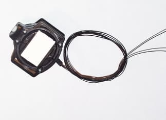
Click to zoom
Application Details
- Equipment Class
- DXX - Part 15 Low Power Communication Device Transmitter
- Date of Grant
- Nov 20, 2000
- Application Purpose
- Original Equipment
- Date of Application
- Jul 15, 2000
- Equipment Note
- Tamper Sensor, Tag
- Frequency Range
- 433.92000000 - 433.92000000
- Company
- Elpas Solutions Ltd.
- Country
- Israel
Documents & Files
Document Text
Text extracted from the exhibit documents filed with the FCC. Open a document above to read the original.
Users Manual
Wrist Tag Instruction Manual and Specsheet FCC Compliance The F CC Wa nts Y ou to Know This equipment has been tested and found to comply with the limits for a Class B digital device, pursuant to Part 15 of the FCC rules. These limits are designed to provide reasonable protection against harmful interference in a residential installation. This equipment generates, uses and can radiate radio frequency energy and, if not installed and used in accordance with the instructions, may cause harmful interference to radio communications. However, there is no guarantee that interference will not occur in a particular installation. If this equipment does cause harmful interference to radio or television reception, which can be determined by tuning the equipment off and on, the user is encouraged to try to correct the interference by one or more of the following measures: a) Reorient or relocate the receiving antenna. b) Increase the separation between the equipment and receiver. c) Connect the equipment to an outlet on a circuit different from that to which the receiver is connected. d) Consult the dealer or an experienced radio/TV technician. FCC Warning Modifications not expressly approved by manufacturer could void the user authority to operate the equipment under FCC rules. IR and RF Wrist Tag P/N: PWB00901 (433.92 MHz) IR/RF Wris t T ag Description A small, wrist-worn portable tag, capable of transmitting ID-coded IR beams, and in addition, RF signals in the frequency of 433.92 MHz. The tag is used for the purpose of locating patients in enclosed environments. General Electrical power source One 3-Volt lithium battery Data rate 19,200 bits per second Message protocol 4 bytes proprietary format Message duration 2.08 ms Battery type CR 2032 Renata Battery life One year, assuming movement 12 hr / day Battery status indication Battery status transmitted with every RF and IR message. Badge ID Unique factory programmed (ID code, transmit rate, motion sensor activation and deactivation, etc.) Button press 4 transmissions (200 ms apart) at 0.4 sec intervals with the motion bit on (B1 indicates button press) Dimensions 47 x 37.1 x 14.7 mm. Height from band holders - 17.6 mm Weight (including battery) 25 gram. Temperature: Operating -10 to 70 ° C Temperature: Storage -20 to 60 ° C Humidity: Operating 5 to 95% RH @ 70 ° C Humidity: Storage 5 to 95% RH @ 85 ° C Water resistance Waterproof Accessories One disposable hospital band (included) IR Transmission Modulation ASK (Amplitude Shift Keying of IR carrier) Peak optical transmitted power 500mW Peak transmission wavelength 880nm Peak radiant intensity 120 mW/Sr Frequency of transmission Carrier at 455 KHz Transmission rate Motionless: IR is transmitted on every 3 rd RF transmission, (RF is transmitted 200ms after IR). In Motion: every 4sec (200 ms apart) Transmission angle 360 ° badge plane. ± 60 ° to badge perpendicular axis. RF Transmission RF 433.92 MHz Modulation ASK (Amplitude Shift Keying of 433.92 MHz carrier) Average effective radiated power In motion: less than –35 dbm. Motionless: less than –45 dbm Stability + / - 20ppm Peak ERP -15 dbm (max) Transmission pattern Omnidirectional FCC and CE compliance FCC Part 15.231 Level C I-ETS 300 220-1 Using the Wrist Tag The following is a set of procedures to ensure proper use of the Wrist Tag. To use the Wrist Tag: 1. Attach the strap of the Wrist Tag aro und the patient’s wrist. 2. Keep the IR transmission area clear. 3. Press butto n to activate it. 4. The RDRs within the facility pick up the signals. Battery Replacement The battery is located inside the Wrist Tag. In order to replace the battery, you need to open the back side of the Wrist Tag with a Phillips screwdriver (preferably an electric one) with point size "0". For example, the APEX #4910. A new battery can then be inserted, after which the screws must be replaced.
Users Manual
Equipment Tag with Input Instruction Manual and Specsheet FCC Compliance The F CC Wa nts Y ou to Know This equipment has been tested and found to comply with the limits for a Class B digital device, pursuant to Part 15 of the FCC rules. These limits are designed to provide reasonable protection against harmful interference in a residential installation. This equipment generates, uses and can radiate radio frequency energy and, if not installed and used in accordance with the instructions, may cause harmful interference to radio communications. However, there is no guarantee that interference will not occur in a particular installation. If this equipment does cause harmful interference to radio or television reception, which can be determined by tuning the equipment off and on, the user is encouraged to try to correct the interference by one or more of the following measures: a) Reorient or relocate the receiving antenna. b) Increase the separation between the equipment and receiver. c) Connect the equipment to an outlet on a circuit different from that to which the receiver is connected. d) Consult the dealer or an experienced radio/TV technician. FCC Warning Modifications not expressly approved by manufacturer could void the user authority to operate the equipment under FCC rules. IR and RF Equipment Tag with Input P/N: WSE00433 (433.92 MHz) Description A small, attachable portable device, capable of transmitting Infra Red signals in addition to RF signals in the frequency of 433.92 MHz. It is used for the purposes of locating, monitoring and protecting mobile equipment in enclosed environments and for providing various location dependent f unctions. The inclusio n of the input provides an indicatio n of the “short” and “open” states of the input. General Input Short – accepts dry contacts of less than 10k Ω Open – accepts dry contacts more than 1M Ω Note: No voltage should be applied between the two input wires. Transmissions The transfer from open to short or from short to open triggers the following transmissions: Open to short – 4 badge transmissions at 0.4 sec apart with B2 high Short to open - 4 badge transmissions at 0.4 sec apart with B2 low In Steady State, B2 indicates the following input states: Low – open High – short Electrical power source One 3-Volt lithium battery Data rate 19,200 bits per second Message protocol 4 bytes proprietary format Message duration 2.08 ms Battery type CR 2032 Renata Battery life Five years, assuming movement 1 hr / day Battery status indication Battery status transmitted with every RF and IR message Badge ID Unique factory programmed (ID code, transmit rate, motion sensor activation and deactivation, etc.) Dimensions 39 x 39 x 16 mm Weight (including battery) 25 gram Temperature: Operating -10 to 70 ° C Temperature: Storage -20 to 60 ° C Humidity: Operating 5 to 95% RH @ 70 ° C Humidity: Storage 5 to 95% RH @ 85 ° C Water resistance Waterproof IR Transmission Modulation ASK (Amplitude Shift Keying of IR carrier) Peak optical transmitted power 500mW Peak transmission wavelength 880nm Peak radiant intensity 120 mW/Sr Frequency of transmission Carrier at 455 KHz Transmission rate During movement – every 3 to 5 sec message. During rest (no movement) – every 60 sec. Transmission angle 360 ° badge plane. ± 60 ° to badge perpendicular axis. RF Transmission 433.92 MHz Modulation ASK (Amplitude Shift Keying of 433.92 MHz carrier) Average effective radiated power In motion: less than –35 dbm. Motionless: less than –45 dbm Stability +/- 20ppm Peak ERP -15 dbm (max) Transmission pattern Omnidirectional FCC compliance FCC Part 15.231 Level C Using the Equipment Tag with Input The following is a set of procedures to ensure proper use of the Equipment Tag. To use the Equipment Tag with Input: 1. Use some glue to attach the Equipment Tag to a piece of equipment. 2. A press butto n is available, if required. 3. Connect the two wires together to activate the input sensor. Battery Replacement The Equipment Tag co ntains a standard Lithium battery of type CR2032. The battery is located inside the Equipment Tag. In order to replace the battery, you need to open the back side of the equipment tag with a Phillips screwdriver (preferably an electric one) with point size "0". For example, the APEX #4910. A new battery can then be inserted, after which the screws must be replaced.
Users Manual
Equipment Tag with Input Instruction Manual and Specsheet FCC Compliance The F CC Wa nts Y ou to Know This equipment has been tested and found to comply with the limits for a Class B digital device, pursuant to Part 15 of the FCC rules. These limits are designed to provide reasonable protection against harmful interference in a residential installation. This equipment generates, uses and can radiate radio frequency energy and, if not installed and used in accordance with the instructions, may cause harmful interference to radio communications. However, there is no guarantee that interference will not occur in a particular installation. If this equipment does cause harmful interference to radio or television reception, which can be determined by tuning the equipment off and on, the user is encouraged to try to correct the interference by one or more of the following measures: a) Reorient or relocate the receiving antenna. b) Increase the separation between the equipment and receiver. c) Connect the equipment to an outlet on a circuit different from that to which the receiver is connected. d) Consult the dealer or an experienced radio/TV technician. FCC Warning Modifications not expressly approved by manufacturer could void the user authority to operate the equipment under FCC rules. 15.9 (a) Labeling Requirements This device complies with Part 15 of the FCC Rules. Operation is subject to the following two conditions. (1) This device may not cause harmful interference, and (2) this device must accept any interference received, including interference that may cause undesired operation. IR and RF Equipment Tag with Input P/N: WSE00433 (433.92 MHz) Description A small, attachable portable device, capable of transmitting Infra Red signals in addition to RF signals in the frequency of 433.92 MHz. It is used for the purposes of locating, monitoring and protecting mobile equipment in enclosed environments and for providing various location dependent f unctions. The inclusio n of the input provides an indicatio n of the “short” and “open” states of the input. General Input Short – accepts dry contacts of less than 10k Ω Open – accepts dry contacts more than 1M Ω Note: No voltage should be applied between the two input wires. Transmissions The transfer from open to short or from short to open triggers the following transmissions: Open to short – 4 badge transmissions at 0.4 sec apart with B2 high Short to open - 4 badge transmissions at 0.4 sec apart with B2 low In Steady State, B2 indicates the following input states: Low – open High – short Electrical power source One 3-Volt lithium battery Data rate 19,200 bits per second Message protocol 4 bytes proprietary format Message duration 2.08 ms Battery type CR 2032 Renata Battery life Five years, assuming movement 1 hr / day Battery status indication Battery status transmitted with every RF and IR message Badge ID Unique factory programmed (ID code, transmit rate, motion sensor activation and deactivation, etc.) Dimensions 39 x 39 x 16 mm Weight (including battery) 25 gram Temperature: Operating -10 to 70 ° C Temperature: Storage -20 to 60 ° C Humidity: Operating 5 to 95% RH @ 70 ° C Humidity: Storage 5 to 95% RH @ 85 ° C Water resistance Waterproof IR Transmission Modulation ASK (Amplitude Shift Keying of IR carrier) Peak optical transmitted power 500mW Peak transmission wavelength 880nm Peak radiant intensity 120 mW/Sr Frequency of transmission Carrier at 455 KHz Transmission rate During movement – every 3 to 5 sec message. During rest (no movement) – every 60 sec. Transmission angle 360 ° badge plane. ± 60 ° to badge perpendicular axis. RF Transmission 433.92 MHz Modulation ASK (Amplitude Shift Keying of 433.92 MHz carrier) Average effective radiated power In motion: less than –35 dbm. Motionless: less than –45 dbm Stability +/- 20ppm Peak ERP -15 dbm (max) Transmission pattern Omnidirectional FCC compliance FCC Part 15.231 Level C Using the Equipment Tag with Input The following is a set of procedures to ensure proper use of the Equipment Tag. To use the Equipment Tag with Input: 1. Use some glue to attach the Equipment Tag to a piece of equipment. 2. A press butto n is available, if required. 3. Connect the two wires together to activate the input sensor. Battery Replacement The Equipment Tag co ntains a standard Lithium battery of type CR2032. The battery is located inside the Equipment Tag. In order to replace the battery, you need to open the back side of the equipment tag with a Phillips screwdriver (preferably an electric one) with point size "0". For example, the APEX #4910. A new battery can then be inserted, after which the screws must be replaced.
Cover Letter(s)
October 26, 2000 11 Hasadna St., Industrial Zone, P.O.B 2571, Raanana 43650, ISRAEL Te l : 972 9 7760200 Fax: 972 9 7460593 E-mail: [email protected] Saved: 10/26/00 3:11 PM Printed: 10/26/00 3:23 PM` Shlomo Yasur Confidentiality- FCC ID O4XB08.doc Federal Communications Commission Equipment Approval Services P.O. Box 358315 Pittsburgh, PA 15251-5315 Subject: Confidentiality for FCC Application FCC ID O4XB08 Confirmation Number EA98200 of ELPAS Electro-optic Systems Ltd. Dear Madam/Sir, Due to the proprietary design developed by ELPAS Electro-optic systems Ltd. that is unique to the industry, ELPAS Electro-optic Systems Ltd. Is requesting confidentiality for the following exhibits of ELPAS Electro-optic systems Ltd.: FCC ID: O4XB08 Confirmation No.: EA98200 Report No.: E36112.00 1. Block Diagram. 2. Schematics. 3. Bill Of Materials. Please feel free to contact me with any questions. Best Regards, Shlomo Yasur V. P Engineering & Operations
External Photos
ELPAS External Photos WSE00433 External Photo Top View External Photo Bottom View
ID Label/Location Info
ELPAS Product Labeling WSE00433 FCC Label Location of Label on EUT
ID Label/Location Info
ELPAS Product Labeling WSE00433 FCC Label Location of Label on EUT
Internal Photos
ELPAS Internal Photos WSE00433 PCB Two sides
Operational Description
Wrist / Equipment IR/RF 433 Tags – Wrist / Equipment IR/RF 433 Tags –Wrist / Equipment IR/RF 433 Tags – Wrist / Equipment IR/RF 433 Tags – P/N WSE00433 P/N WSE00433P/N WSE00433 P/N WSE00433 Equipment tags can be attached to mobile equipment directly or using an attachment device. Equipment tags are used to keep track of valuable mobile equipment or other assets in the workplace. Users UsersUsers Users Normally, equipment tags are placed on mobile equipment. For example: computers, fetal monitors, laboratory equipment, and so on. However, they may also be worn or carried by people. ✦ A sticker on the back of the equipment tag indicates the identification number of the tag. Battery Type and Replacement Battery Type and ReplacementBattery Type and Replacement Battery Type and Replacement The equipment tag contains a standard Lithium battery of type CR2032. The battery is located inside the equipment tag. In order to replace the battery, you need to open the back side of the equipment tag with a Phillips screwdriver (preferably an electric one) with point size "0". For example, the APEX #4910. A new battery can then be inserted, after which the screws must be replaced. IR Emission IR EmissionIR Emission IR Emission Infra-red signals are emitted from the upper black surface of the equipment tag. Therefore, when attaching the equipment tag, it is necessary to keep the upper surface free from obstructio n. Operation OperationOperation Operation The equipment tag transmits IR signals periodically. The default time period is every four seconds . However, ELPAS can reconfigure the default time period. When the tag is static, the badge transmits every 60 seconds. This time period can also be reconfigured by ELPAS. The equipment tag transmits RF signals periodically. The default time period is 10 seconds . However, ELPAS can reconfigure the default time period. When the tag is static, the badge transmits every 60 seconds. This time period can also be reconfigured by ELPAS. The equipment tag, like all EIRIS™ badges, should be placed externally, facing outward. Otherwise, the range of transmission is reduced because infra-red signals do not travel through non-transparent objects. Button Press Button PressButton Press Button Press A push button is located on the side of the tag. Pressing the push button initiates a special message in a similar way to that of the personal badge.
Test Report
FCC ID O4XB08 Electrical (EMC) Test Report E36112.00ELPAS - Electro-optic Systems Ltd. Page 1 of 34 FCC DOC M Ver 1.12 04 April 2000 DATE: 09 July 2000 I.T.L. (PRODUCT TESTING) LTD. FCC EMC Test Report for ELPAS - Electro-optic Systems Ltd. Equipment under test: Wrist/Equipment IR/RF 433, Tamper Sensor, Tag WSE00433 Approved by:_____________________________ L. Barry , Test Engineer Approved by:_____________________________ I. Raz, EMC Laboratory Manager This report must not be reproduced, except in full, without the written permission of I.T.L. (Product Testing) Ltd. This report relates only to items tested. . FCC ID: O4XB08 Test Report E36112.00ELPAS - Electro-optic Systems Ltd. Page 2 of 34 FCC DOC M Ver 1.12 04 April 2000 Measurement/Technical Report for ELPAS - Electro-optic Systems Ltd. Equipment under test: Wrist/Equipment IR/RF 433, Tamper Sensor, Tag P/N WSE00433 FCC ID: O4XB08 DATE: 09 July 2000 This report concerns:Original Grant x Class II change ___ Class B verification Class A verification Class I change ____ Equipment type: Radio Telemetry Transmitter Request Issue of Grant: x Immediately upon completion of review Limits used: CISPR 22 Part 15 x Measurement procedure used is ANSI C63.4-1992. Application for Certification Applicant for this device: prepared by:(different from "prepared by") Ishaiahou RazShlomo Yasur ITL (Product Testing) Ltd.ELPAS–Electro-optic Systems Ltd. POB 21111 Hasadna St. Or Yehuda 60251Raanana 43650 IsraelIsrael Tel: 972-3-533 9022Tel: 972-9-776 0200 Fax:+972-3-5339019Fax: 972-9-746 0593 FCC ID: O4XB08 Test Report E36112.00ELPAS - Electro-optic Systems Ltd. Page 3 of 34 FCC DOC M Ver 1.12 04 April 2000 TABLE OF CONTENTS 1.GENERAL INFORMATION -----------------------------------------------------------------------------4 1.1Product Description.................................................................................... 4 1.2Test Methodology...................................................................................... 5 1.3Test Facility............................................................................................... 5 1.4Measurement Uncertainty ........................................................................... 5 2.PRODUCT LABELING----------------------------------------------------------------------------------6 3.SYSTEM TEST CONFIGURATION-------------------------------------------------------------------7 3.1Justification................................................................................................ 7 3.2EUT Exercise Software .............................................................................. 7 3.3Special Accessories ................................................................................... 7 3.4Equipment Modifications ............................................................................. 7 Configuration of Tested System............................................................................ 7 4.BLOCK DIAGRAM ---------------------------------------------------------------------------------------8 4.1Schematic Block/Connection Diagram.......................................................... 8 5.RADIATED EMISSION DATA --------------------------------------------------------------------------9 5.1Radiated Emission 10KHz-1000 MHz, Below 1GHz...................................... 9 5.2Measured Data.......................................................................................... 9 5.3Test Instrumentation Used, Radiated Measurements .................................. 12 5.4Field Strength Calculation ......................................................................... 13 6.RADIATED EMISSION DATA ------------------------------------------------------------------------ 14 6.1Radiated Emission Above 1 GHz............................................................... 14 6.2Test Data ................................................................................................ 14 6.3Test Instruments used, Radiated Measurement Above 1 GHZ ..................... 17 6.4Field Strength Calculation ......................................................................... 18 7.FUNDAMENTAL EMISSION BANDWIDTH-------------------------------------------------------- 19 7.1Test Specification..................................................................................... 19 7.2Test Procedure........................................................................................ 19 7.3Measured Data........................................................................................ 19 7.4Test Instrumentation Used, Fundamental Emission Band Width.................... 23 8.PHOTOGRAPHS OF TESTED E.U.T. ------------------------------------------------------------- 24 9.SIGNATURES OF THE E.U.T'S TEST ENGINEERS ------------------------------------------- 27 10.APPENDIX A - CORRECTION FACTORS--------------------------------------------------------- 28 10.1 Correction factors for CABLE................................................................... 28 10.2 Correction factors for CABLE................................................................... 29 10.3 Correction factors for LOG PERIODIC ANTENNA ..................................... 30 10.4 Correction factors for BICONICAL ANTENNA............................................. 31 10.5 Correction factors for BICONICAL ANTENNA Type 3109............................ 32 10.6 Correction factors for BICONICAL ANTENNA Type 3109............................ 33 10.7 Correction factors for SAS ANTENNA, 3 meter range................................. 34 FCC ID: O4XB08 Test Report E36112.00ELPAS - Electro-optic Systems Ltd. Page 4 of 34 FCC DOC M Ver 1.12 04 April 2000 1. General Information 1.1 Product Description FCC ID: O4XB08 Test Report E36112.00ELPAS - Electro-optic Systems Ltd. Page 5 of 34 FCC DOC M Ver 1.12 04 April 2000 1.2 Test Methodology Both conducted and radiated testing were performed according to the procedures in ANSI …
Text truncated - open the document above for the full version.
Test Setup Photos
Test Setup Photographs WSE00433 Radiated Emissions Front/Top View Side View
Contact Information
Applicant
Arick Elshtein(International Compliance Manager)
Technical Contact
Israel Testing Laboratories -Kfar Bin NunShaike Raz
[email protected]972-8-9797799
11 Hasadna St. · Or Yehuda · Israel
Non-Technical Contact
ELPAS - Electro-optic Systems Ltd.Shlomo Yasur
972-9-7760200
Test Firm
Israel Testing LaboratoriesIIan Cohen
Technical Specifications
| # | Rule Parts | Frequency Range | Power Output |
|---|---|---|---|
| 1 | 15C | 433.92 MHz - 433.92 MHz | - |
Other Applications from Elpas Solutions Ltd.
O4X5-WTG411210
Aug 27, 2015Quad Technology Wrist Tag
Equipment Class
DCD - Part 15 Low Power Transmitter Below 1705 kHz
O4X5-LW2410370
Apr 27, 2015Lone Worker Active RFID Tag
Equipment Class
DSR - Part 15 Remote Control/Security Device Transceiver
O4X5-LCA004331
Apr 01, 2015Enhanced Local Controller
Equipment Class
DSR - Part 15 Remote Control/Security Device Transceiver
O4X5-ALC01121-0
Mar 17, 2015ALC LF BUS Beacon, indoor/outdoor 125 kHz + 433 MHz
Equipment Class
DSR - Part 15 Remote Control/Security Device Transceiver
O4X5-ALC01021-0
Feb 11, 2015ALC LF BUS Beacon 5-ALC01021-0, 5-ALC11021-0
Equipment Class
DCD - Part 15 Low Power Transmitter Below 1705 kHz