O87-1167POCSAG transmitter
Sea Air and Land Communications
Click to zoom
Application Details
- Equipment Class
- TNB - Licensed Non-Broadcast Station Transmitter
- Date of Grant
- Apr 29, 2001
- Application Purpose
- Original Equipment
- Date of Application
- Nov 20, 2000
- Equipment Note
- POCSAG transmitter
- Frequency Range
- 140.00000000 - 162.00000000
- Country
- New Zealand
Documents & Files
Document Text
Text extracted from the exhibit documents filed with the FCC. Open a document above to read the original.
Users Manual
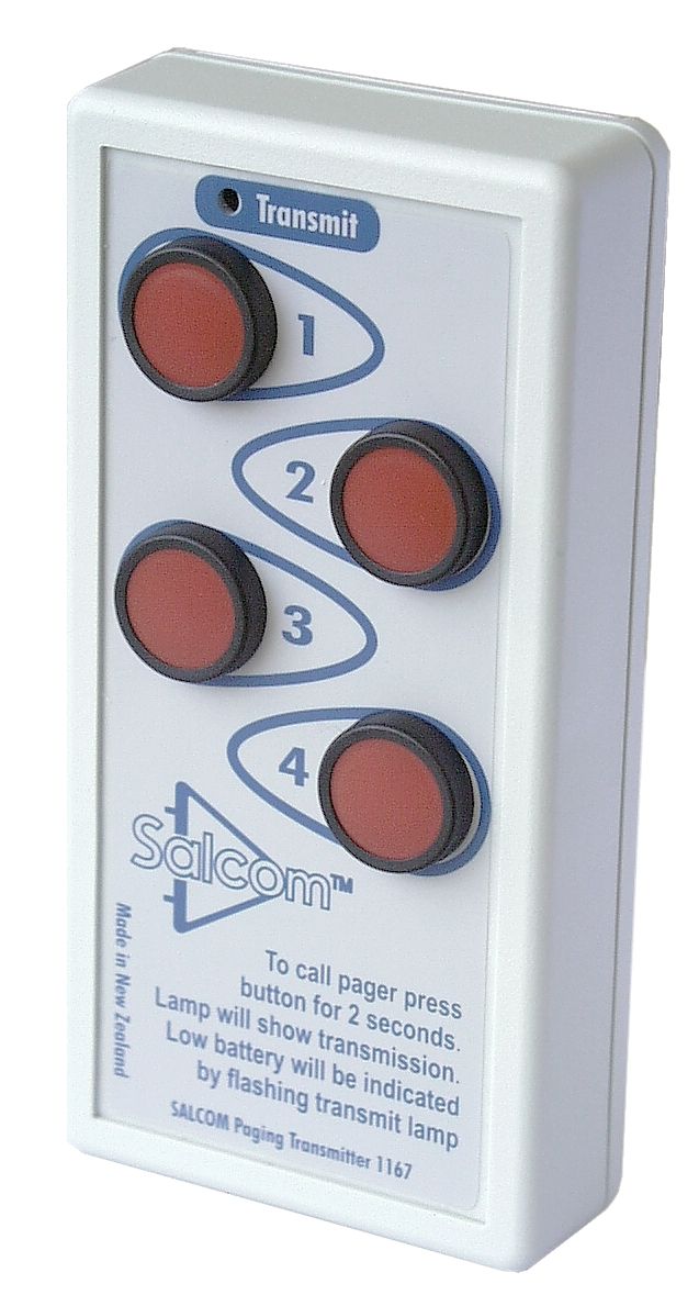
11-67-0000 POCSAG PERSONAL TRANSMITTER USER=S MANUAL Sea Air and Land Communications Ltd POCSAG Personal Transmitter 11-67-0000 Users Manual Also covers SALCOM products 1143, 1170 and 1187 1.0DESCRIPTION: The SALCOM POCSAG Personal Transmitter is a simple to use, compact hand held paging message transmitter. The unit has four buttons, with which any one of four user definable paging messages can be sent to a pocket pager or any paging message receiver. Each message can be Tone Only, Numeric or Alphanumeric, and can be repeated from 1 to 99 times. The unit runs from a user replaceable 9v alkaline battery, giving an operational life of over 1000 messages. The user can program the content of the messages using SALCOM product support software and accompanying interface adaptor. A small LED on the front panel shows transmission and inter-transmission breaks. 2. 0WARRANTY: Our Products are warranted for a period of 12 months from date of purchase against faulty materials and workmanship. Should any fault occur the unit should be returned to the vendor, freight pre-paid. Please include a description of the fault to assist with prompt return. Any unauthorized alterations or repairs will invalidate the warranty. 3.0DISCLAIMER: All information provided in this document is carefully prepared and offered in good faith as a guide in the installation, use and servicing of our products. Users must ensure that the final application satisfies the relevant regulatory requirements. We accept no responsibility for inappropriate application. We reserve the right to change product and specifications data at any time, without notice. CAUTION: Changes or modifications not expressly approved by the party responsible for compliance could void the user's authority to operate the equipment. 11-67-0000 POCSAG PERSONAL TRANSMITTER USER=S MANUAL Sea Air and Land Communications Ltd 4.0SPECIFICATIONS TRANSMITTER Nominal frequency band140 - 162MHz Output (into 50ohms)+18dBm "2dB Spurious outputs-30dBc max. Conducted test MESSAGE PARAMETERS Number of messages4 For each of the four messages:- RIC code7 digit (codes 0 to 2097151) Message typeTone, Numeric, Alphanumeric Function levels1,2,3 or 4 Length of message0 to 70 characters Baud rate512 or 1200 bps Transmission count1 to 99 Delay between transmission retries1 to 99 seconds Common message0 to 35 characters ID number storage4 numeric characters GENERAL Battery type9v Alkaline (12v A23 for 1143) Low battery threshold voltage7 volts (9v for 1143) Environment protection standardIP443 Weight56 grams Size64mm x 26mm x 130mm 5.0OPERATION: The11-67 is operated by pressing one of the four buttons on the front panel. Each button must be held down for half a second before transmission commences to allow for accidental presses. Transmission is indicated by the TX LED illuminating. If transmission retries have been selected, the unit will go into a wait period between transmissions indicated by the TX LED flashing faintly. Cessation of transmissions is indicated by the TX LED going off completely. 11-67-0000 POCSAG PERSONAL TRANSMITTER USER=S MANUAL Sea Air and Land Communications Ltd A number of factors can influence the range of the unit. The range can be optimised by applying the following rules: 1. Ensure the path between transmitter and receiver is as clear from obstructions as possible. 2. Do not mount the unit on metal surfaces. 2. Replace batteries when they become exhausted. 3. If handheld, hold the unit in the open with one hand as far from the body as possible. 4. Some pocket pager receivers do not respond as well as fixed receivers with external aerials 6.0LOW BATTERY INDICATION: The transmitted output power and range of the unit will decrease as the battery becomes exhausted. The TX lamp flashing when any button is pressed indicates low battery voltage. For optimum performance, the battery should be replaced as soon as possible after the flashing lamp is observed. The battery can recover slightly if the unit is left without a button being pressed for a period, and the next time a button is pressed, it may not flash. Do not consider this a reason not to replace the battery. 7.0BATTERY REPLACEMENT: Remove the cover from the rear of the unit. Replace the battery with the designated type ensuring the polarity is correct and the connector contacts are tight. If the battery is inserted backwards, the unit will not be damaged, but it will not function. Ensure that the TX lamp lights when a button is pressed and check for any ingress of dirt into the case. Note: The 1143 product requires the front cover to be removed to change the battery. 7.1 BATTERY TYPE: The table below shows the correct battery type for the various product variants. Product TypeVoltageType Number 1167, 1170, 1187 Alkaline9 voltsMN1604, 6LR61 1143Alkaline12 voltsA23 8. 0PROG RAMM ING : The 1167 can be programmed using an IBM TM compatible personal computer, a SALCOM 1146 serial adapter and the SALCOM 1143PSD programming software. 8.1 Loading the program: The program is loaded and run according to the instructions supplied with the software. 11-67-0000 POCSAG PERSONAL TRANSMITTER USER=S MANUAL Sea Air and Land Communications Ltd 8.2 Serial adaptor: The serial adaptor is plugged into a serial port (com1). Once the program is running, the default configuration can be opened from disk or the existing 1167 configuration can be read via the serial adapter (if connected to the 1167 - see 8.4) and edited. 8.3 Edit menu: Under the EDIT menu, each button has a separate window, allowing the parameters of each buttons' transmission to be changed. A fifth edit window allows the user to add a unit ID number, and inset a common message which will be added to the start of every transmission. This can be made to reflect the Unit ID and hence identify the unit from its transmission. 8.4 Attaching the serial adaptor to the 11-67: Remove the back cover of the 1167 and plug the head of the serial adaptor into the four pin conne…
Text truncated - open the document above for the full version.
Block Diagram
126371 Revision A Date 11/00 Page 1 Micro- processor 3686kHz OSC EErom Crystal Oscillator Amplifier FC Amplifier Push Button Power Control and regulator Transmit indicator PTT MOD Push Button Push Button Push Button Tuned Loop Antenna Fc Filter FcFilter Fc Block Diagram of SALCOM 1167, 1170, 1187, 1143 Fc/3
ID Label/Location Info
126369 Revision A Date 11/00 Page 1 This device complies with part 15 of the FCC Rules. Operation is subject to the following two conditions: (1) This device may not cause harmful interference. (2) This device must accept any interference received, including interference that may cause undesired operation. SALCOM 1167 Transmitter FCC ID O87-00001
ID Label/Location Info
127722 Revision B Date 7/12/00 Page 1 This device complies with part 15 of the FCC Rules. Operation is subject to the following two conditions: (1) This device may not cause harmful interference. (2) This device must accept any interference received, including interference that may cause undesired operation. SALCOM 1167 Transmitter FCC ID: O87-1167
Operational Description
126376 RevA Date 11/00 Page 1 Operational Description of SALCOM 1167 POCSAG transmitter. Microprocessor logic. The processor section consists of a low cost Microcontroller, a EEROM memory and a crystal oscillator. At power ON, the processor reads the button status, and encodes a POCSAG message according to the pre-programmed message held in EEROM. The processor then asserts PTT, enabling the RF crystal oscillator and buffer stages, and then frequency modulates the oscillator with the data. The data modulation is NRZ type. Low battery condition is detected at this stage, by comparing a sample of the supply voltage with the regulated 5v rail, and is indicated by the LED flashing. Radio Frequency section. The crystal oscillator Q1 generates one third of the final output carrier frequency, and is modulated by using a switched capacitor in the crystal circuit. The modulation frequency shift is approx +/-1.33kHz giving +/-4kHz shift of the final carrier. The data modulation is NRZ type. The output of the oscillator passes through a band pass filter, L4,L2, to remove the fundamental component, and pass the third harmonic. This is then amplified in two transistor stages Q2,Q7, to produce approx 100mW output. The final low pass filter L7,C14,C15 and tuned loop antenna removes other spurious frequency products from the transmission. EIRP is approximately 0.2mW. The PTT output from the processor controls the bias to the oscillator and first amplifier. All other stages are Class C and draw current only when driven with RF. The processor can turn off the transmitter between transmissions using the PTT control line. Power control and regulator. Any button has the ability to enable the power control circuit and turn on the unit. Once power has reached the regulator and released the reset circuit, the processor can hold the power on, and only release it when the transmission is finished. The battery supply input is protected from reverse polarity with a series diode.
Schematics
1 2 3 4 5 6 78 ABCD 8 7 6 5 4 3 2 1 D CBA Title Number Revision Size A3 Date: 22-Nov-2000 Sheet of File: V:\Products\11670000\SCH\1167\1167.ddb Drawn By: R11K L26.5T/3 L3 6.5T/3 L4 6.5T/3 L5 15.5T/4 WITH CORES C710N C933P C101P Q1 BFR92A Q2 BFR92A X1 GG13s C11 39PC1247P C810N C1333P R2560R R43K9 R5 6K8 R6220R R7 1K R847K R947R R3 560R L7 5.5T/3 L8 10.5/3.5C D2 BAS16 D3BAS16 C1415P RST 1 RD-P30 2 TD-P31 3 XTAL2 4 XTAL1 5 I0-P32 6 I1-P33 7 T0-P34 8 T1-P35 9 GND 10 P37 11 A0-P10 12 A1-P11 13 P12 14 P13 15 P14 16 P15 17 P16 18 P17 19 VCC 20 IC1AT89C2051 1 1 KPB 11-70 WALL MOUNT PAGING TRANSMITTER 10/98 S1 PB switch S2 Not Fitted S3 Not Fitted S4 Not Fitted D4BAS16D5BAS16D6BAS16D7BAS16 R1010KR146K8 C16100N C28100N X2 3686KHZ C3033P C3133P R15 1K C32100P C33100P C1810NC1910NC2010N SW1SW2SW3 SW4 SW1SW2SW3SW4MOD PTT MOD C2110N R1110K R17 1K C2210N SHUTDOWN C2310N C63-10p OUT 1 SEN 2 SHTDWN 3 GND 4 PWROK 5 5VTAP 6 FBACK 7 INPUT 8 IC3LP2951 R1210K VDD VDD R1310K C29100N 1234 J1 HDR 4WAY RA C2410N R163K3 VBATT SDASCL PTTDRIVE SERRX SERTX RESET Q7PH2369 C3510N C1539P D8BAT54 D9BAS16 D10BAS16 D11BAS16 D12BAS16 C2610N +8V +8V VDD C27 100N C36SOT C3710N Q4 BC807 Q3BC807 Q5BC847 Q6BC847 C25100N C34100N C38100N R191K R182K7 VDD R204K7 R214K7 VDD 11-70-0000 VDD C1710N C410P C2 12P C5 12P R22100KR2347K +8V C39100N R246K8 C4010N C4110N 2.4vac 1.0vac 3.2vac 1.3vac 6.3vac 2.4vac -1v DC AC test voltages measured with diode probe with TX into dummy load For 1 D1LED-3MM BD1F29 Bead BD2F29 Bead Battery Connector B1 BATTERY C11.5-5P L1 LOOP 1.0/204MM Switches S1,2,3,4 fitted Offboard A0 1 A1 2 A2 3 RC 7 SCL 6 SDA 5 VDD 8 VSS 4 IC2AT24C04A 12 P1Battery Snap Connector VDD Figure 1 Circuit diagram
Test Report
22 November 2000 EMC Technologies (NZ) Ltd Test Report No 00912.2 Report date: 22 November 2000 EM C Te chnolog ie s (NZ) Lt d Telephone: +64 9 360 0862 Fax: +64 9 360 0861 STREET ADDRESS - 47 MacKelvie Street, Gre y Lynn, Auck la nd, New Zea la ndE- ma il: aucklab@ ihug.co.nz POSTAL ADDRESS - PO Box 68 307, Newton, Auckland, New ZealandWeb Site: www.emctech.com.au T his re po rt may not be re produce d e xce pt i n f ull Page 1 of 12 TEST REPORT Salcom 11-67 POCSAG Paging Transmitter tested for compliance with the Code of Federal Regulations (CFR) 47 Part 90 –Private Land Mobile Services for Sea Air and Land Communications Ltd This Test Report is issued with the authority of: ______________________________________ Andrew Cutler - General Manager EMC Technologies (NZ) Ltd Test Report No 00912.2 Report date: 22 November 2000 EM C Te chnolog ie s (NZ) Lt d Telephone: +64 9 360 0862 Fax: +64 9 360 0861 STREET ADDRESS - 47 MacKelvie Street, Gre y Lynn, Auck la nd, New Zea la ndE- ma il: aucklab@ ihug.co.nz POSTAL ADDRESS - PO Box 68 307, Newton, Auckland, New ZealandWeb Site: www.emctech.com.au T his re po rt may not be re produce d e xce pt i n f ull Page 2 of 12 Table of Contents 1. CLIENT INFORMATION3 2.DESCRIPTION O F TEST SAMPLE3 4.ARTICLES SUBMITTED4 5.TEST SAMPLE DESCRIPTION5 7.ATTESTATION6 8.TRANSMITTER TEST RESULTS7 9.TEST EQUIPMENT USED10 10.ACCREDITATIONS10 11. PHOTOGRAPH(S) 12 APPENDIX A: SPECTRUM PLOT 12a EMC Technologies (NZ) Ltd Test Report No 00912.2 Report date: 22 November 2000 EM C Te chnolog ie s (NZ) Lt d Telephone: +64 9 360 0862 Fax: +64 9 360 0861 STREET ADDRESS - 47 MacKelvie Street, Gre y Lynn, Auck la nd, New Zea la ndE- ma il: aucklab@ ihug.co.nz POSTAL ADDRESS - PO Box 68 307, Newton, Auckland, New ZealandWeb Site: www.emctech.com.au T his re po rt may not be re produce d e xce pt i n f ull Page 3 of 12 1.CLIENT INFORMATION Company Name Sea Air and Land Communications Ltd Address 120 St Asaph Street PO Box 22-621 City Christchurch Country New Zealand Contact Kelvin Barnsda le 2.DESCRIPTION OF TEST SAMPLE Brand Name Sa lcom Model Number 11-67 Product POCSAG Paging Transmitter Manufacturer Sea Air and Land Communications Ltd Country of Origin New Zealand Serial Number Not serialised FCC ID Not marked EMC Technologies (NZ) Ltd Test Report No 00912.2 Report date: 22 November 2000 EM C Te chnolog ie s (NZ) Lt d Telephone: +64 9 360 0862 Fax: +64 9 360 0861 STREET ADDRESS - 47 MacKelvie Street, Gre y Lynn, Auck la nd, New Zea la ndE- ma il: aucklab@ ihug.co.nz POSTAL ADDRESS - PO Box 68 307, Newton, Auckland, New ZealandWeb Site: www.emctech.com.au T his re po rt may not be re produce d e xce pt i n f ull Page 4 of 12 3. SUMMARY OF TEST RESULTS Testing was carried out in accordance with the test methods defined in 47 CFR Part 2 and 90. Listed below are the relevant Part 2 test methods and the limits defined in Part 90. CLAUSE TEST PERFORMED RESULT 2.1041Measurement proceduresNoted 2.1046RF power outputNoted 2.1049Occupied bandwidthNoted 2.1051Spurious emissions at antenna terminalsNoted 2.1057Frequency spectrum to be investigatedNoted 90.217Exemption from technical standards Complies 4.ARTICLES SUBMITTED 1 x Salcom 11-67 POCSAG Paging Transmitter. This transmitter is a handheld unit which has the following functions: - Red LED transmit indicator - 4 red transmit buttons labelled 1 to 4 - button 1: modified to continuous transmit an alphanumeric message. - buttons 2 –4: momentary paging messages. The transmitter has an integral antenna. The sample supplied for testing however was fitted with an external antenna connection in order to make testing easier. EMC Technologies (NZ) Ltd Test Report No 00912.2 Report date: 22 November 2000 EM C Te chnolog ie s (NZ) Lt d Telephone: +64 9 360 0862 Fax: +64 9 360 0861 STREET ADDRESS - 47 MacKelvie Street, Gre y Lynn, Auck la nd, New Zea la ndE- ma il: aucklab@ ihug.co.nz POSTAL ADDRESS - PO Box 68 307, Newton, Auckland, New ZealandWeb Site: www.emctech.com.au T his re po rt may not be re produce d e xce pt i n f ull Page 5 of 12 5. TEST SAMPLE DESCRIPTION The sample tested is a POCSAG paging transmitter with the following specifications: Rated Transmitter Output Power 18.0 dBm +/- 2 dB ( 40 mW – 100 mW) Test frequency 160.5125 MHz Frequency Range 140.0 – 162.0 MHz Emission Type POCSAG paging modulation. Power Supply 9 Vdc internal battery. Antenna Internal tuned loop. 6. Test Conditions Standard Temperature and Humidity Temperature:+25°C ± 4° maintained. Relative Humidity:60% ± 10% observed. Standard Test Power Source Internal 9 Vdc battery. EMC Technologies (NZ) Ltd Test Report No 00912.2 Report date: 22 November 2000 EM C Te chnolog ie s (NZ) Lt d Telephone: +64 9 360 0862 Fax: +64 9 360 0861 STREET ADDRESS - 47 MacKelvie Street, Gre y Lynn, Auck la nd, New Zea la ndE- ma il: aucklab@ ihug.co.nz POSTAL ADDRESS - PO Box 68 307, Newton, Auckland, New ZealandWeb Site: www.emctech.com.au T his re po rt may not be re produce d e xce pt i n f ull Page 6 of 12 7. ATTESTATION This report describes the tests and measurements performed for the purpose of determining compliance with the specification with the following conditions: The test sample was selected by the client. The report relates only to the sample tested. This report does not contain corrections or erasures. Measurement uncertainties with statistical confidence intervals of 95% are shown below test results. Both Class A and Class B uncertainties have been accounted for, as well as influence uncertainties where appropriate. In addition this equipment has been tested in accordance with the requirements contained in the appropriate Commission re gulations. To the best of my knowledge, these tests were performed using measurement procedures that are consistent with industry or Commission standards and demonstrate that the equipment complies with the appropriate standards. Each unit manufactured, imported, or marketed, as defined in the Commission’s regulations, will conform to th…
Text truncated - open the document above for the full version.
Contact Information
Applicant
Alan Jacks(Operations Manager)
Test Firm
EMC Technologies NZ Ltd.Andrew Cutler
Technical Specifications
| # | Rule Parts | Frequency Range | Power Output | Emission | Tolerance |
|---|---|---|---|---|---|
| 1 | 90 | 140 MHz - 162 MHz | 74.00 mW | 20K0F1D | 10.0000000000 ppm |
Other Applications from Sea Air and Land Communications

O87-20620450
Jun 22, 2020UHF Paging Transceiver
Equipment Class
TNB - Licensed Non-Broadcast Station Transmitter
O87-20620150
Jun 21, 2020VHF Paging Transceiver
Equipment Class
TNB - Licensed Non-Broadcast Station Transmitter
O8712865
Jul 07, 2014MINIATURE POCSAG UHF TRANSMITTER
Equipment Class
TNB - Licensed Non-Broadcast Station Transmitter
O871290
Nov 01, 2012LICENSED NON-BROADCAST STATION TRANSMITTER
Equipment Class
TNB - Licensed Non-Broadcast Station Transmitter
O871185
Jun 30, 2004UHF Pocket Paging Transmitter
Equipment Class
TNT - Licensed Non-Broadcast Transmitter Worn on Body