O871178UHF Pocsag Paging Transmitter
Sea Air and Land Communications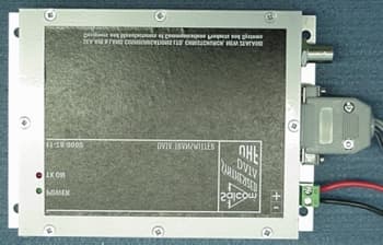
Click to zoom
Application Details
- Equipment Class
- TNB - Licensed Non-Broadcast Station Transmitter
- Date of Grant
- Nov 08, 2001
- Application Purpose
- Original Equipment
- Date of Application
- Aug 22, 2001
- Equipment Note
- UHF Pocsag Paging Transmitter
- Frequency Range
- 450.00000000 - 470.00000000
- Country
- New Zealand
Documents & Files
Document Text
Text extracted from the exhibit documents filed with the FCC. Open a document above to read the original.
Users Manual
11-75-0000 SYNTHESIZED UHF 4 WATT PAGING TRANSMITTER TECHNICAL MANUAL Sea Air and Land Communications Ltd, PO Box 22-621, 120 St Asaph Street, Christchurch, New Zealand 11-75-0000 SYNTHESIZED PAGING TRANSMITTER TECHNICAL MANUAL Issue 0600 Sea Air and Land Communications Ltd Page 2 11-75 POCSAG PAGING TRANSMITTER 1.0 DESCRIPTION The 11-75 is a stand-alone 4 watt POCSAG paging transmitter with an in-built encoder. The unit can be controlled via an RS232 serial interface to provide numeric, alphanumeric and tone-only POCSAG encoding. This enables a user to call a pager (over 2,000,000 codes), append an appropriate priority level (1 of 4), and add a numeric or alphanumeric message. Messages are limited to 120 characters by the 11-75 buffer size, and to 240 character pre-def ined messages by the Product Support Disk (PSD) programming software. Serial control is achieved using ASCII character commands.The unit supports 12 discrete inputs with a different pre-programmed message on high and/or low transition, plus a low voltage detection message on the power input. The inputs can be configured for a number of options. They can be configured to act as 12 individual inputs or binary code inpu ts to select pager number, pager message and level. Provision to transmit a message more than once is also catered for as well as a variable time between trans missions. In addition to the SALCOM propriety protocol, the RS232 serial port can be used to initiate paging transmissions using the Pagi ng Entry Protocol (PET) or Telocator Alphanumeric Protocol (TAP) PG1 protocol. For dial-up applications, a HAYES compatible modem is also supported. 11-75-0000 SYNTHESIZED PAGING TRANSMITTER TECHNICAL MANUAL Issue 0600 Sea Air and Land Communications Ltd Page 3 1.1 11-75 Circuit Description: Q7 VCO oscillates at the output frequency determined by L2, C68 and D5 capacity. L2 is trimmed to adjust get the oscillator to a frequency close to the output frequency and output from the synthesizer keeps the frequency phase locked to the reference frequ ency of 6.25kHz or 12.5kHz. The synthesizer derives a voltage from it's phase comparator and adjusts the capacity of D5 via the VCO loop to keep the oscill ator phase locked to the reference frequency. Reference frequency is derived by the synthesizer dividing down the 9.6MHz crystal oscillator.Output from the VCO is transferred via C71 to a buffer/amplifier stage which splits the signal, part is fed to the synthesizer to be divided down for the phase comparator and part goes to Q9 RF amplifier. The signal is further amplified by Q10, Q12, Q13 to provide a 4 Watt maximum outpu t. A 3 section filter L14, L15, L16 and associated capacitors filters the output harmonics to less than -30dBm.RV3 adjusts Q13 quiescent current to 150mA cold.Q15, Q16, Q17 provides Output Power Adjustment via the Setup Program which controls Q15 via R85 and IC8 pin 9. Q15-Q17 is also controlled by an 'out of lock' signal from IC7F & IC7E and an over temperature signal from IC7D. Q14 provides instant control over Q13 bias current from PTT or Out-of-lock. POCSAG modulation is applied as dual-point modulation to D3 (Low Speed), and to D6 (High Speed). Deviation + and - is set via t he Setup Program and IC8, Q3, Q4, control that level. RV2 adjusts the proportion of HS and LS modulation to keep the demodulated waveform as close to a s quare wave as possible. Over temperature cutout: When the unit transmits at full power in a hot environment, a protective cutout may operate. This will reduce the output power to a safe level, and will reset when the unit temperature has fallen to below 60 deg. This cutout is designed to avoid permanent damage to the transmitter. 11-75-0000 SYNTHESIZED PAGING TRANSMITTER TECHNICAL MANUAL Issue 0600 Sea Air and Land Communications Ltd Page 4 1.2 Year 2000 compliance statement: SALCOM has made every effort towards year 2000 compliant systems and software. However, as our products are often used as system integration tools or rely on other systems, we cannot fully determine their behaviour in every environment . Full Y2K Compliance can be defined as follows:(1) No value for current date will cause any interruption in operation (2) Date based functionality must behave consistently for dates prior to, during and after year 2000 (3) In all interfaces and data storage, the century in any date must be specified either explicitly or by unambiguous algorithms or rules (like a 'pivot' date) (4) Year 2000 must be recognized as a leap year The 11-75-0000 has no internal time or date reference. It is therefore inherently Year 2000 compliant. 2.0 WARRANTY Our Products are warranted for a period of 12 months from date of purchase against faulty materials and workmanship. Should an y fault occur the unit should be returned to the vendor, freight pre-paid. Please include a description of the fault to assist with prompt return. Any unauthor ized alterations or repairs will invalidate the warranty. 3.0 DISCLAIMER All information provided in this document is carefully prepared and offered in good faith as a guide in the installation, use a nd servicing of our products. Installers must ensure that the final installation operates satisfactorily within the relevant regulatory requirements. We accept no responsibi lity for incorrect installation. We reserve the right to change products, specifications, and installation data at any time, without notice. 11-75-0000 SYNTHESIZED PAGING TRANSMITTER TECHNICAL MANUAL Issue 0600 Sea Air and Land Communications Ltd Page 5 4.0 MECHANICAL DESCRIPTION The 1175 is enclosed in a pressed aluminium box.The lid will unclip to reveal 16 screw terminals, and adjustment for the low supply detector. The lid can also be used for mou nting the unit on a wall, and the overhang can be cut or modified to allow cable entry as required. It is advisable to mount the unit away from sources of heat, damp or v ibration. 5.0 INSTALLATION The power supply should be connected as illustra…
Text truncated - open the document above for the full version.
Users Manual
11-75-0000 SYNTHESIZED UHF 4 WATT PAGING TRANSMITTER OPERATOR’S MANUAL Sea Air and Land Communications Ltd, PO Box 22-621, 120 St Asaph Street, Christchurch, New Zealand 11-75-0000 SYNTHESIZED PAGING TRANSMITTER OPERATOR’S MANUAL Issue 09/99 Sea Air and Land Communications Ltd Page 4 11-75 POCSAG PAGING TRANSMITTER 1.0 DESCRIPTION The 11-75 is a stand-alone 4 watt POCSAG paging transmitter with an in-built encoder. The unit can be controlled via an RS232 serial interface to provide numeric, alphanumeric and tone-only POCSAG encoding. This enables a user to call a pager (over 2,000,000 codes), append an appropriate priority level (1 of 4), and add a numeric or alphanumeric message. Messages are limited to 120 characters by the 11-75 buffer size, and to 240 character pre-def ined messages by the Product Support Disk (PSD) programming software. Serial control is achieved using ASCII character commands.The unit supports 12 discrete inputs with a different pre-programmed message on high and/or low transition, plus a low voltage detection message on the power input. The inputs can be configured for a number of options. They can be configured to act as 12 individual inputs or binary code inpu ts to select pager number, pager message and level. Provision to transmit a message more than once is also catered for as well as a variable time between trans missions. In addition to the SALCOM propriety protocol, the RS232 serial port can be used to initiate paging transmissions using the Pagi ng Entry Protocol (PET) or Telocator Alphanumeric Protocol (TAP) PG1 protocol. For dial-up applications, a HAYES compatible modem is also supported. 1.1 Over temperature cutout: When the unit transmits at full power in a hot environment, a protective cutout may operate. This will reduce the output power to a safe level, and will reset when the unit temperature has fallen to below 40 deg. This cutout is designed to avoid permanent dam age to the transmitter. 1.2 Year 2000 compliance statement: SALCOM has made every effort towards year 2000 compliant systems and software. However, as our products are often used as system integration tools or rely on other systems, we cannot fully determine their behaviour in every environment.Full Y2K Compliance can be defined as follows:(1) No value for current date will cause any interruption in operation (2) Date based functionality must behave consistently for dates prior to, during and after year 2000 (3) In all interfaces and data storage, the century in any date must be specified either explicitly or by unambiguous algorithms or rules (like a 'pivot' date) (4) Year 2000 must be recognized as a leap year The 11-75 has no internal time or date reference. It is therefore inherently Year 2000 compliant. 2.0 WARRANTY Our Products are warranted for a period of 12 months from date of purchase against faulty materials and workmanship. Should an y fault occur the unit should be returned to the vendor, freight pre-paid. Please include a description of the fault to assist with prompt return. Any unauthor ized alterations or repairs will invalidate the 11-75-0000 SYNTHESIZED PAGING TRANSMITTER OPERATOR’S MANUAL Issue 09/99 Sea Air and Land Communications Ltd Page 5 warranty. 3.0 DISCLAIMER All information provided in this document is carefully prepared and offered in good faith as a guide in the installation, use a nd servicing of our products. Installers must ensure that the final installation operates satisfactorily within the relevant regulatory requirements. We accept no responsibi lity for incorrect installation. We reserve the right to change products, specifications, and installation data at any time, without notice. 11-75-0000 SYNTHESIZED PAGING TRANSMITTER OPERATOR’S MANUAL Issue 09/99 Sea Air and Land Communications Ltd Page 6 4.0 MECHANICAL DESCRIPTION The 11-75 is enclosed in a pressed aluminium box.The lid will unclip to reveal 16 screw terminals, and adjustment for the low supply detector. The lid can also be used for mou nting the unit on a wall, and the overhang can be cut or modified to allow cable entry as required. It is advisable to mount the unit away from sources of heat, damp or v ibration. 5.0 INSTALLATION The power supply should be connected as illustrated on page 5, at a voltage shown in the specification. The supply input is protected against reversed connection. The aerial connection is via the BNC connector, and should present a nominal load of 50 Ω , with a VSWR of better than 1.8:1. It is recommended to site the aerial a few metres away from the 11-75 to avoid RF feedback causing problems with the transmitter operation. An outside aerial is preferab le, as it will provide better radio coverage.External indicators consist of a power indicator GREEN LED, normally ON with very brief flashes to indicate healthy micro-cont roller operation. After a de-bounce period, the green LED will flash rapidly if the low supply detector is activated.The RED LED will indicate when the unit is transmitting. A flashing RED LED indicates the unit cannot transmit as either the sy nthesiser is out of lock or the channel busy input is active. 11-75-0000 SYNTHESIZED PAGING TRANSMITTER OPERATOR’S MANUAL Issue 09/99 Sea Air and Land Communications Ltd Page 7 6.0 OPERATION The 11-75 can transmit three types of POCSAG message, with any one of four function levels:• Alphanumeric transmissions. Message can contain any alphanumeric ‘ASCII’ character. • Numeric transmissions. Message contains only Numeric characters and some symbols. • Tone Only transmissions (Alphanumeric or numeric with no message) 6.1 Alphanumeric transmissions Messages can contain any alphanumeric character. The 11-75 w ill accept the standard ASCII 7 bit character set . 6.2 Numeric transmissions Messages can contain numeric characters and some symbols. These can convey a telephone number, or other numerically coded infor mation. The transmitted message is shorter, and therefore there is a smaller chance of errors rece…
Text truncated - open the document above for the full version.
Users Manual
11-78-0000 SYNTHESIZED UHF 4 WATT NRZ DATA TRANSMITTER PRODUCT INFORMATION Sea Air and Land Communications Ltd, PO Box 22-621, 120 St Asaph Street, Christchurch, New Zealand 11-78-0000 SYNTHESIZED NRZ DATA TRANSMITTER PRODUCT INFOIssue 11787TA Sea Air and Land Communications LtdPage 1 11-78 NRZ UHF DATA TRANSMITTER 1.0DESCRIPTION The 11-78 is a stand-alone 4 watt NRZ data paging transmitter. It has a special modulator design capable of transmitting frequency shift keying down to DC, using a dual point modulation synthesizer. The unit can be configured via an RS232 serial interface adapter (SALCOM 11-46) using the Product Support Disk (PSD) programming software. The unit supports three inputs, PTT, DATA and BUSY. An internal data delay can be selected for use in simulcast networks, and a “maximum on air timer” (MOAT) can be implemented. An independent PTT output is available, controlled by the MOAT or BUSY functions, for enabling external power amplifiers or aerial changeover relays. Over temperature cutout: When the unit transmits at full power in a hot environment, a protective cutout may operate. This will reduce the output power to a safe level, and will reset when the unit temperature has fallen to below 70 deg. This cutout is designed to avoid permanent damage to the transmitter. 1.1Year 2000 compliance statement: SALCOM has made every effort towards year 2000 compliant systems and software. However, as our products are often used as system integration tools or rely on other systems, we cannot fully determine their behaviour in every environment. Full Y2K Compliance can be defined as follows: (1)No value for current date will cause any interruption in operation (2)Date based functionality must behave consistently for dates prior to, during and after year 2000 (3)In all interfaces and data storage, the century in any date must be specified either explicitly or by unambiguous algorithms or rules (like a 'pivot' date) (4)Year 2000 must be recognized as a leap year The 11-78-0000 has no internal time or date reference. It is 11-78-0000 SYNTHESIZED NRZ DATA TRANSMITTER PRODUCT INFOIssue 11787TA11-78-0000 SYNTHESIZED NRZ DATA TRANSMITTER PRODUCT INFOIssue 11787TA Sea Air and Land Communications LtdPage 2Sea Air and Land Communications LtdPage 3 therefore inherently Year 2000 compliant.External indicators consist of a power indicator GREEN LED, normally 2.0WARRANTY The RED LED will indicate when the unit is transmitting. A flashing Our Products are warranted for a period of 12 months from date of purchase against faulty materials and workmanship. Should any fault occur the unit should be returned to the vendor, freight pre-paid. Please include a description of the fault to assist with prompt return. Any unauthorized alterations or repairs will invalidate the warranty.The 1178 will power on, and will remain in the standby mode until the 3.0DISCLAIMER 7.0INITIATING TRANSMISSIONS All information provided in this document is carefully prepared andThe transmitter will be placed in transmit mode by the PTT (Press To offered in good faith as a guide in the installation, use and servicing ofTalk) input being taken low. It will then turn the carrier on at the preset our products. Installers must ensure that the final installation operatespower level, as defined in the configuration. The carrier frequency will satisfactorily within the relevant regulatory requirements. We accept nofollow the Data1 input, a high input giving high frequency shift. responsibility for incorrect installation. Data2 input acts as a channel busy inhibit, when taken low it will stop We reserve the right to change products, specifications, and installation data at any time, without notice.An input can be initiated with a transition to LOW (connection to GND 4.0MECHANICAL DESCRIPTION >+3.5v). The 1178 is enclosed in a solid aluminium box. All electrical connections are made via the D15 socket S2 or P2, the two pin power connector. If the 1178 does not perform as required, the following points may lead The unit can be mounted on a wall with 4 screws. It is advisable toto solving the problem. mount it away from sources of heat, damp or vibration. 5.0INSTALLATION The configuration of the unit should be completed before installation. The power supply should be connected as illustrated, at a voltage shown in the specification. The supply input is protected against reversed connection. The aerial connection is via the BNC connector, and should present a nominal load of 50 O, with a VSWR of better than 1.8:1. It is recommended to site the aerial a few metres away from the 1178 to avoid any possibility of RF feedback causing problems with the transmitter operation. An outside aerial is preferable, as it will provide better radio coverage. ON with very brief flashes to indicate healthy micro-controller operation. RED LED indicates the unit cannot transmit as either the synthesiser is out of lock or the channel busy input is active. 6.0OPERATION PTT input is activated. the transmitter coming on air. or connection to <+3.5v) or HIGH (input floating or connection to 8.0TROUBLE SHOOTING FaultCheck No illumination of Green LEDBad power supply connection PTT input activated but noTransmit inhibit /Channel busy input transmission, red LED flashesactive. Unit transmits but nothing receivedPoor aerial. Wrong frequency, Power too low. Unit too hot. Too much vibration No RS232 serial communicationComport connections, baud-rate (9600) no parity, eight data bits, one stop bit Red LED flashes rapidly. NoFrequency out of range, Channel busy synthesizer lock.active. Unit starts, but does not completePoor supply volts, RF interference. transmission Does not remain in transmit mode“Max On Air Time” too short 11-78-0000 SYNTHESIZED NRZ DATA TRANSMITTER PRODUCT INFOIssue 11787TA11-78-0000 SYNTHESIZED NRZ DATA TRANSMITTER PRODUCT INFOIssue 11787TA Sea Air and Land Communications LtdPage 4Sea Air and Land Communications LtdPage 5 9.0TUNING AND TEST Equipme…
Text truncated - open the document above for the full version.
Attestation Statements
EMC Technologies (NZ) Ltd Test Report No 00813 FCC Report date: 23 August 2001 EMC Technologies (NZ) Lt d Telephone: +64 9 360 0862 Fax: +64 9 360 0861 STREET ADDRESS - 47 MacKelvie Street, Grey Lynn, Auckland, New Zealand E-mail: [email protected] POSTAL ADDRESS - PO Box 68 307, Newton, Auckland, New Zealand Web Site: www.emctech.com.au This re po rt may not be re pro duce d e xce pt i n ful l ATTESTATION This report describes the tests and measurements performed for the purpose of determining compliance with the specification with the following conditions: The test sample was selected by the client. The report relates only to the sample tested. This report does not contain corrections or erasures. Measurement uncertainties with statistical confidence intervals of 95% are shown below test results. Both Class A and Class B uncertainties have been accounted for, as well as influence uncertainties where appropriate. In addition this equipment has been tested in accordance with the requirements contained in the appropriate Commission re gulations. To the best of my knowledge, these tests were performed using measurement procedures that are consistent with industry or Commission standards and demonstrate that the equipment complies with the appropriate standards. Each unit manufactured, imported, or marketed, as defined in the Commission’s regulations, will conform to the sample(s) tested with the variations statistical basis. I further certify that the necessary measurements were made by EMC Technologies NZ Ltd, 47 MacKelvie Street, Grey Lynn, Auckland, New Zealand. Andrew Cutler General Manager EMC Technologies NZ Ltd
Cover Letter(s)
DESIGNERS AND MANUFACTURERS OF COMMUNICATIONS SYSTEMSPage 1 SEA AIR AND LAND COMMUNICATIONS LTD 120 ST ASAPH STREET, PO BOX 22-621, CHRISTCHURCH, NEW ZEALAND Phone: +64 3 379-2298 Fax: +64 3 365-1580 Email: [email protected] 20 August 2001 Andrew Cutler General Manager EMC Technologies PO Box 68 307 Newton Auckland Dear Andrew Please accept this letter as authorisation to act on our behalf in applying to the FCC for certification to FCC Part 90 for Salcom’s 11-78 and 11-75 UHF 4 Watt POCSAG Transmitters. Thankyou Yours faithfully John Croft Engineering Manager Sea Air & Land Communications (Salcom) Ltd Christchurch New Zealand
Cover Letter(s)
DESIGNERS AND MANUFACTURERS OF COMMUNICATIONS SYSTEMSPage 1 SEA AIR AND LAND COMMUNICATIONS LTD 120 ST ASAPH STREET, PO BOX 22-621, CHRISTCHURCH, NEW ZEALAND Phone: +64 3 379-2298 Fax: +64 3 365-1580 Email: [email protected] 20 August 2001 11-78 and 11-75 4 Watt NRZ UHF POCSAG Transmitters Details of 11-78 & 11-75 Circuitry Similarities/Differences Same circuitry; RF lineup, synthesizer, modulator amp, modulator -low speed & high speed, VTXCO and RF oscillator, power control circuit, voltage regulators, micro-controller - substantial parts of circuitry, VCO lock. Differences; Input circuitry; -to pcb mounted terminal blocks (11-75), -to pcb mounted D15 socket (11-78) Power Connection; - to pcb mounted terminal blocks (11-75), -to pcb mounted power plug (11-78). Power adjustment/turndown circuit; 11-78 = 100mW to 4 Watt, 11-75 = 4 Watts only. Slew limiter, data generator. Comments; Differences between 11-78 and 11-75 relate to the input circuitry, data train generator circuitry and power adjustment circuitry. The 11-75 generates its own data train whereas the 11-78 accepts a data train on its input. On both, the data train passes to the modulator via the micro-controller, so integrity of the data shape is maintained or controlled. The 11-78 uses an rf power feedback circuitry to accurately adjust and control power at 100mW (EC requirement). John Croft Engineering Manager Sea Air & Land Communications (Salcom) Ltd Christchurch New Zealand
External Photos
EMC Technologies (NZ) Ltd Test Report No 00813 FCC Report date: 23 August 2001 EMC Technologies (NZ) Lt d Telephone: +64 9 360 0862 Fax: +64 9 360 0861 STREET ADDRESS - 47 MacKelvie Street, Grey Lynn, Auckland, New Zealand E-mail: [email protected] POSTAL ADDRESS - PO Box 68 307, Newton, Auckland, New Zealand Web Site: www.emctech.com.au This re po rt may not be re pro duce d e xce pt i n ful l PHOTOGRAPH
ID Label/Location Info
SALCOM1178UHFPOCSAGTransmitter FCCID:O87-1178 SeaAir&LandCommunicationsLtd Christchurch,NewZealand Labelsize:45mmx20mm
ID Label/Location Info
SALCOM1178UHFPOCSAGTransmitter FCCID:O871178 SeaAir&LandCommunicationsLtd Christchurch,NewZealand
Internal Photos
EMC Technologies (NZ) Ltd Test Report No 00813 FCC Report date: 23 August 2001 EMC Technologies (NZ) Lt d Telephone: +64 9 360 0862 Fax: +64 9 360 0861 STREET ADDRESS - 47 MacKelvie Street, Grey Lynn, Auckland, New Zealand E-mail: [email protected] POSTAL ADDRESS - PO Box 68 307, Newton, Auckland, New Zealand Web Site: www.emctech.com.au This re po rt may not be re pro duce d e xce pt i n ful l PHOTOGRAPH (S) EMC Technologies (NZ) Ltd Test Report No 10813.1 Report date: 21 August 2001 EM C Te chnolog ie s (NZ) Lt d Telephone: +64 9 360 0862 Fax: +64 9 360 0861 STREET ADDRESS - 47 MacKelvie Street, Gre y Lynn, Auck la nd, New Zea la ndE- ma il: aucklab@ ihug.co.nz POSTAL ADDRESS - PO Box 68 307, Newton, Auckland, New ZealandWeb Site: www.emctech.com.au T his re po rt may not be re produce d e xce pt i n f ull
Operational Description
SEA AIR AND LAND COMMUNICATIONS LTD 120 ST ASAPH STREET, PO BOX 22-621, CHRISTCHURCH, NEW ZEALAND Phone: +64 3 379-2298 Fax: +64 3 365-1580 Email: [email protected] 11-78 Power Output, Output Stage Current and Applied Voltage To produce 4 Watts of r.f. output power and with a supply voltage of +13.8V to the 11-78, the r.f. final output stage Q13 will draw typically 850mA and have an applied voltage of 11.5 Volts. This equates to 9.775 Watts d.c. input power
Operational Description
SEA AIR AND LAND COMMUNICATIONS LTD 120 ST ASAPH STREET, PO BOX 22-621, CHRISTCHURCH, NEW ZEALAND Phone: +64 3 379-2298 Fax: +64 3 365-1580 Email: [email protected] 11-78 Circuit Description: Q7 VCO oscillates at the output frequency determined by L2, C68 and D5 capacity. L2 is trimmed to adjust the oscillator to a frequency close to the output frequency and output from the synthesizer keeps the frequency phase locked to the reference frequency of 6.25kHz or 12.5kHz. The synthesizer derives a voltage from it's phase comparator and adjusts the capacity of D5 via the VCO loop to keep the oscillator phase locked to the reference frequency. Reference frequency is derived by the synthesizer dividing down the 9.6MHz crystal oscillator. Output from the VCO is transferred via C71 to a buffer/amplifier stage which splits the signal, part is fed to the synthesizer to be divided down for the phase comparator and part goes to Q9 RF amplifier. The signal is further amplified by Q10, Q12, Q13 to provide a 4 Watt maximum output. For a 4 Watt output and supply voltage of +13.8V, Q13 will typically draw 850mA with an applied voltage of 11.5 Volts. A 3 section filter L14, L15, L16 and associated capacitors filters the output harmonics to less than -36dBm. RV3 adjusts Q13 quiescent current to 150mA. IC9B, Q3 provides Output Power Adjustment via the Setup Program which controls IC9B via R10 and IC4 pins 14-19. Q3 is also controlled by an 'out of lock' signal from IC9B & IC3F and an over temperature signal from IC3D. Q14 provides instant control over Q13 bias current from PTT or Out-of-lock. POCSAG modulation is applied to input DATAIN1, pin 13 on S2, is buffered by IC2C, passes via IC4 to IC9A and is applied as dual-point modulation to D3 (Low Speed), and to D6 (High Speed). Deviation + and - is set via the Setup Program and IC4 pins 24-31 and its associated resistor network control that level. RV2 adjusts the proportion of HS and LS modulation to keep the demodulated waveform as close to a square wave as possible. Over temperature cutout: When the unit transmits at full power in a hot environment, a protective cutout may operate. R76 NTC resistor will operate IC3D and IC9B via D8, reducing the transmitter voltage from Q3. This will reduce the output power to a safe level, and will reset when the unit temperature has fallen to below 60 deg. This cutout is designed to avoid permanent damage to the transmitter.
Schematics
SEA AIR AND LAND COMMUNICATIONS LTD 120 ST ASAPH STREET, PO BOX 22-621, CHRISTCHURCH, NEW ZEALAND Phone: +64 3 379-2298 Fax: +64 3 365-1580 Email: [email protected] 11-78 Circuit Description: Q7 VCO oscillates at the output frequency determined by L2, C68 and D5 capacity. L2 is trimmed to adjust the oscillator to a frequency close to the output frequency and output from the synthesizer keeps the frequency phase locked to the reference frequency of 6.25kHz or 12.5kHz. The synthesizer derives a voltage from it's phase comparator and adjusts the capacity of D5 via the VCO loop to keep the oscillator phase locked to the reference frequency. Reference frequency is derived by the synthesizer dividing down the 9.6MHz crystal oscillator. Output from the VCO is transferred via C71 to a buffer/amplifier stage which splits the signal, part is fed to the synthesizer to be divided down for the phase comparator and part goes to Q9 RF amplifier. The signal is further amplified by Q10, Q12, Q13 to provide a 4 Watt maximum output. A 3 section filter L14, L15, L16 and associated capacitors filters the output harmonics to less than -36dBm. RV3 adjusts Q13 quiescent current to 150mA. IC9B, Q3 provides Output Power Adjustment via the Setup Program which controls IC9B via R10 and IC4 pins 14-19. Q3 is also controlled by an 'out of lock' signal from IC9B & IC3F and an over temperature signal from IC3D. Q14 provides instant control over Q13 bias current from PTT or Out-of-lock. POCSAG modulation is applied to input DATAIN1, pin 13 on S2, is buffered by IC2C, passes via IC4 to IC9A and is applied as dual-point modulation to D3 (Low Speed), and to D6 (High Speed). Deviation + and - is set via the Setup Program and IC4 pins 24-31 and its associated resistor network control that level. RV2 adjusts the proportion of HS and LS modulation to keep the demodulated waveform as close to a square wave as possible. Over temperature cutout: When the unit transmits at full power in a hot environment, a protective cutout may operate. R76 NTC resistor will operate IC3D and IC9B via D8, reducing the transmitter voltage from Q3. This will reduce the output power to a safe level, and will reset when the unit temperature has fallen to below 60 deg. This cutout is designed to avoid permanent damage to the transmitter.
Schematics
VCO LOOP IC5 SYNTH. Q7 VCO TCX1 9.6MHz VTCXO Q15,Q16,Q17 RF POWER SUPPLY/ REGULATOR IC1, IC2 12x INPUT BUFFERS 12x INPUTS IC4 RS232 TX/RX P10 SERIAL INPUT +13.8V GROUND S1 BNC HS ModLS Mod OOL PTT 11-75 UHF POCSAG TRANSMITTER IC10 +5V REG IC9 +8V REG. IC7 OUT OF LOCK DET. Q9,Q10,Q12,Q13 RF AMPLIFIERS IC3 MICRO- CONTROLLER Q8 BUFFER IC6 MOD. AMP. /LIMITER 4W
Schematics
VCO LOOP IC5 SYNTH. Q7 VCO TCX1 9.6MHz VTCXO +13.8V GROUND S1 BNC HS ModLS Mod OOL PTT 11-78 UHF POCSAG TRANSMITTER IC9, Q3 RF POWER SUPPLY/ REGULATOR Q8 BUFFER 4W IC3 OUT OF LOCK DET. IC7 +5V REG IC8 +8V REG. IC2 INPUT BUFFERS 2x INPUTS Q9,Q10,Q12,Q13 RF AMPLIFIERS IC9 MOD. AMP. /LIMITER IC4 MICRO- CONTROLLER
Test Report
23 August 2001 EMC Technologies (NZ) Ltd Test Report No 10813.1 Report date: 21 August 2001 EM C Te chnolog ie s (NZ) Lt d Telephone: +64 9 360 0862 Fax: +64 9 360 0861 STREET ADDRESS - 47 MacKelvie Street, Gre y Lynn, Auck la nd, New Zea la ndE- ma il: aucklab@ ihug.co.nz POSTAL ADDRESS - PO Box 68 307, Newton, Auckland, New ZealandWeb Site: www.emctech.com.au T his re po rt may not be re produce d e xce pt i n f ull Page 1 of 19 TEST REPORT Salcom 11-78 / 11-75 UHF POCSAG Paging Transmitter Tested for compliance with the Code of Federal Regulations (CFR) 47 Part 90 –Private Land Mobile Services for Sea Air & Land Communications Ltd This Test Report is issued with the authority of: ______________________________________ Andrew Cutler - General Manager Prepared By: ________________________________ Karen Miller - Office Administrator EMC Technologies (NZ) Ltd Test Report No 10813.1 Report date: 21 August 2001 EM C Te chnolog…
Text truncated - open the document above for the full version.
Contact Information
Applicant
Alan Jacks(Operations Manager)
Technical Contact
Non-Technical Contact
SALCOMJohn Croft
[email protected]64-3-379-2298
Test Firm
EMC Technologies NZ Ltd.Andrew Cutler
Technical Specifications
| # | Rule Parts | Frequency Range | Power Output | Emission | Tolerance |
|---|---|---|---|---|---|
| 1 | 90.203 (j)(7) | 450 MHz - 470 MHz | 3.8 W | 11K2F1D | 596.0000000000 Hz |
Other Applications from Sea Air and Land Communications

O87-20620450
Jun 22, 2020UHF Paging Transceiver
Equipment Class
TNB - Licensed Non-Broadcast Station Transmitter
O87-20620150
Jun 21, 2020VHF Paging Transceiver
Equipment Class
TNB - Licensed Non-Broadcast Station Transmitter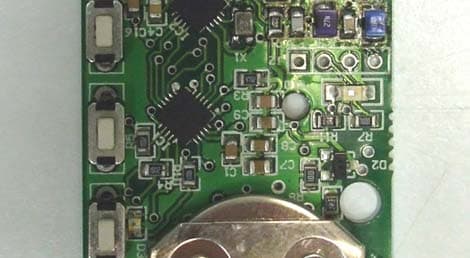
O8712865
Jul 07, 2014MINIATURE POCSAG UHF TRANSMITTER
Equipment Class
TNB - Licensed Non-Broadcast Station Transmitter
O871290
Nov 01, 2012LICENSED NON-BROADCAST STATION TRANSMITTER
Equipment Class
TNB - Licensed Non-Broadcast Station Transmitter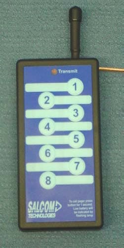
O871185
Jun 30, 2004UHF Pocket Paging Transmitter
Equipment Class
TNT - Licensed Non-Broadcast Transmitter Worn on Body