O8CJM1L2LJM1
Aplix Corporation
Click to zoom
Application Details
- Equipment Class
- DTS - Digital Transmission System
- Date of Grant
- Jun 30, 2015
- Application Purpose
- Original Equipment
- Date of Application
- Jun 30, 2015
- Equipment Note
- JM1
- Frequency Range
- 2402.00000000 - 2480.00000000
- Company
- Aplix Corporation
- Country
- Japan
Documents & Files
Document Text
Text extracted from the exhibit documents filed with the FCC. Open a document above to read the original.
Users Manual
アプリックスIPホールディングス株式会社 http://www.aplix-ip.com/ 7. FCC/IC Notice This device complies with part 15 of FCC Rules and Industry Canada’s licence-exempt RSSs. Operation is subject to the following two conditions: (1) this device may not cause harmful interference, and (2) this device must accept any interference received, including interference that may cause undesired operation. Le présent appareil est conforme à la partie 15 des règles de la FCC et aux normes des CNR d'Industrie Canada applicables aux appareils radio exempts de licence. L'exploitation est autorisée aux deux conditions suivantes : (1) l'appareil ne doit pas produire de brouillage, et (2) l'appareil doit accepter tout brouillage subi, même si le brouillage est susceptible d'en compromettre le fonctionnement. This notice shall display a conspicuous location on the end products as will be described in “9 End Product Labeling”. When the end product is so small or for such use that it is practicable to place the statement, it shall be placed in a prominent location in the instruction manual or pamphlet supplied to the user or, alternatively, shall be placed on the container in which it is marketed. 8. FCC/IC Caution Changes or modifications not expressly approved by the party responsible for compliance, Aplix IP Holdings Corporation, could void the user’s authority to operate the equipment. This transmitter must not be co-located or operated in conjunction with any other antenna or transmitter. This caution shall be placed in the user’s manual or instruction manual of the end product. アプリックスIPホールディングス株式会社 http://www.aplix-ip.com/ 9. End Product Labeling When this module is integrated into an end product, the end product must display an exterior label with FCC ID/IC and the FCC/IC notice as in “7 FCC/IC Notice”. The format of FCC ID/IC is defined as a single line and OEM can choose either of the followings. FCC: Contains Transmitter Module FCC ID: O8CJM1L2L Contains FCC ID: O8CJM1L2L IC: Contains Transmitter Module IC: 10551A-JM1L2L Contains IC: 10551A-JM1L2L 10. End Product User Manuals The end product’s user manual should include the following statements depending on type of the product. Mobile Device: This equipment complies with FCC/IC radiation exposure limits set forth for an uncontrolled environment and meets the FCC radio frequency (RF) Exposure Guidelines and RSS-102 of the IC radio frequency (RF) Exposure rules. This equipment has very low levels of RF energy that it deemed to comply without maximum permissive exposure evaluation (MPE). But it is desirable that it should be installed and operated keeping the radiator at least 20cm or more away from person’s body Cet équipement est conforme aux limites d’exposition aux rayonnements énoncées pour un environnement non contrôlé et respecte les règles d’exposition aux fréquences radioélectriques (RF) CNR-102 de l’IC. Cet équipement émet une énergie RF très faible qui est considérée conforme sans évaluation de l’exposition maximale autorisée (MPE). アプリックスIPホールディングス株式会社 http://www.aplix-ip.com/ Cependant, cet équipement doit être installé et utilisé en gardant une distance de 20 cm ou plus entre le dispositive rayonnant et le corps humain. Portable Device: This equipment complies with FCC/IC radiation exposure limits set forth for an uncontrolled environment and meets the FCC radio frequency (RF) Exposure Guidelines and RSS-102 of the IC radio frequency (RF) Exposure rules. This equipment has very low levels of RF energy that are deemed to comply without testing of specific absorption ratio (SAR). Cet équipement est conforme aux limites d’exposition aux rayonnements énoncées pour un environnement non contrôlé et respecte les règles d’exposition aux fréquences radioélectriques (RF) CNR-102 de l’IC. Cet équipement émet une énergie RF très faible qui est considérée conforme sans évaluation du débit d’absorption spécifique (DAS). The device types are defined as follows. Mobile Device Products operated in the distance more than 20 cm from person’s body. Portable Device Products operated within 20 cm from person’s body. Since this module is not sold to general end users directly, there is no user manual of module. For the details about this module, please refer to the specification sheet of module. This module should be installed in the host device according to the interface specification (installation procedure).
ID Label/Location Info
Label Location JM1L2L PCBA 22 x 13mm Shielding case 15 x 12 x 1.8mm Label on Shielding case 14 x 10mm Note: Since the device is very small, the statement of FCC 15.19(a) is written in product manual.
RF Exposure Info
UL Japan, Inc. Ise EMC Lab 4383-326 Asama-cho, Ise-shi, Mie 516-0021 Japan T:: +81.596.24.8999 / F:: +81.596.24.8124 / W:: ul.com/jp May 27, 2015 UL Japan, Inc. 4383-326 Asama-cho, Ise-shi, Mie 516-0021 Japan FCC ID: O8CJM1L2L To whom it may concern, We, UL Japan, Inc, hereby declare that JM1, model: JM1L2L (FCC ID: O8CJM1L2L) of Aplix IP Holdings Corporation is exempt from RF exposure SAR evaluation as its output power meets the exclusion limits stated in KDB 447498D01(v05r02). KDB 447498D01(v05r02) has the following exclusion for portable devices: The 1g and 10g SAR test exclusion thresholds for 100 MHz to 6 GHz at test separation distances ≤ 50 mm are determined by: [(max. power of channel, including tune-up tolerance, mW)/(min. test separation distance, mm)] ·[√f(GHz)] ≤ 3.0 for 1-g SAR and ≤ 7.5 for 10-g extremity SAR, where •f(GHz) is the RF channel transmit frequency in GHz •Power and distance are rounded to the nearest mW and mm before calculation •The result is rounded to one decimal place for comparison The test exclusions are applicable only when the minimum test separation distance is ≤ 50 mm and for transmission frequencies between 100 MHz and 6 GHz. When the minimum test separation distance is < 5 mm, a distance of 5 mm is applied to determine SAR test exclusion. This device has f = 2.48 GHz and distance = 5 mm (minimum separation distance: 5mm was used in the calculation) and the maximum average output power was 1 mW So for this device: 1 mW[maximum average output power]/5 mm[minimum separation distance]*√2.48 = 0.3 *This is less than 3.0, so no SAR is required. Even taking into account the tolerance, this device can be satisfied with the limits. Thank you for your attention to this matter. Takayuki Shimada Engineer of Ise EMC Lab. Consumer Technology Division UL Japan, Inc.
Test Setup Photos
Test report No. : 10763602H-A Page : 33 of 35 Issued date : May 27, 2015 FCC ID : O8CJM1L2L UL Japan, Inc. Ise EMC Lab. 4383-326 Asama-cho, Ise-shi, Mie-ken 516-0021 JAPAN Telephone : +81 596 24 8999 Facsimile : +81 596 24 8124 APPENDIX 3: Photographs of test setup Conducted Emission Photo 1 Photo 2 Test report No. : 10763602H-A Page : 34 of 35 Issued date : May 27, 2015 FCC ID : O8CJM1L2L UL Japan, Inc. Ise EMC Lab. 4383-326 Asama-cho, Ise-shi, Mie-ken 516-0021 JAPAN Telephone : +81 596 24 8999 Facsimile : +81 596 24 8124 Radiated Spurious Emission Photo 1 Photo 2 Test report No. : 10763602H-A Page : 35 of 35 Issued date : May 27, 2015 FCC ID : O8CJM1L2L UL Japan, Inc. Ise EMC Lab. 4383-326 Asama-cho, Ise-shi, Mie-ken 516-0021 JAPAN Telephone : +81 596 24 8999 Facsimile : +81 596 24 8124 Worst Case Position (Horizontal: Z-axis / Vertical: Z-axis)(Below 1GHz) (Horizontal: X-axis / Vertical: Y-axis)(1-10GHz) (Horizontal: X-axis / Vertical: X-axis)(Above 10GHz) X-axis Y-axis Z-axis End of Report
Contact Information
Applicant
Takahiro Shirakawa(Corporate Officer)
Technical Contact
UL Japan, Inc.Takayuki Shimada
[email protected]81-596-24-8999
4383-326 Asama-cho, Ise-shi · Mie-ken · Japan
Test Firm
UL Japan, Inc. Head office EMC Lab.Tetsuya Hashimoto
Technical Specifications
| # | Rule Parts | Frequency Range | Power Output |
|---|---|---|---|
| 1 | 15C | 2.40 GHz - 2.48 GHz | 800.00 µW |
Other Applications from Aplix Corporation
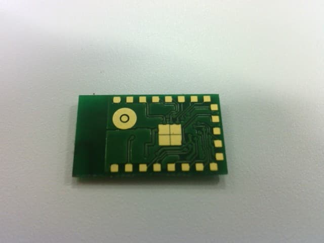
O8CJM1L2X
Dec 18, 2013JM1
Equipment Class
DTS - Digital Transmission System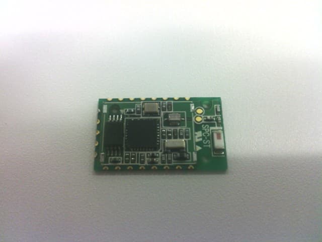
O8CJM1L2S
Aug 01, 2013JM1
Equipment Class
DTS - Digital Transmission System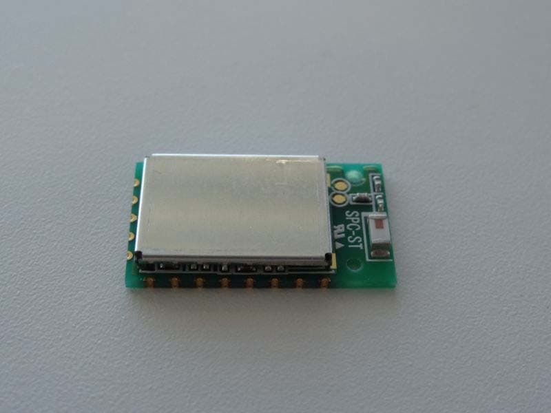
O8CJM1L2
Feb 03, 2013JM1
Equipment Class
DTS - Digital Transmission System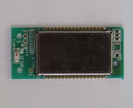
O8CJM1V4
Sep 09, 2012JM1
Equipment Class
DSS - Part 15 Spread Spectrum Transmitter