O8CJM1V4JM1
Aplix Corporation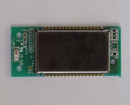
Click to zoom
Application Details
- Equipment Class
- DSS - Part 15 Spread Spectrum Transmitter
- Date of Grant
- Sep 09, 2012
- Application Purpose
- Original Equipment
- Date of Application
- Sep 09, 2012
- Equipment Note
- JM1
- Frequency Range
- 2402.00000000 - 2480.00000000
- Company
- Aplix Corporation
- Country
- Japan
Documents & Files
Document Text
Text extracted from the exhibit documents filed with the FCC. Open a document above to read the original.
Users Manual
User’s manual Product: JM 1 Model: JM1V4 For OEM integration only – device cannot be sold to general public. Therefore we will not supply the User’s manual, the installation manual is the official for OEM. FCC ID: O8CJM1V4 IC: 10551A-JM1V4 We will ask OEM to include the following Notices required by FCC/ IC on the product and in the User’s manual. JM1-V4D1004Z 取扱説明書 Copyright © 2012 Zeemote. All rights reserved. 16 Appendix C: Regulatory Information C.1 FCC/IC Notice This device complies with Part 15 of FCC Rules and Industry Canada license-exempt RSS standard(s). Operation is subject to the following two conditions: (1) this device may not cause interference, and (2) this device must accept any interference, including interference that may cause undesired operation of this device. Le présent appareil est conforme aux la partie 15 des règles de la FCC et CNR d'Industrie Canada applicables aux appareils radio exempts de licence. L'exploitation est autorisée aux deux conditions suivantes : (1) l'appareil ne doit pas produire de brouillage, et (2) l'utilisateur de l'appareil doit accepter tout brouillage radioélectrique subi, même si le brouillage est susceptible d'en compromettre le fonctionnement. C.2 FCC CAUTION Changes or modifications not expressly approved by the party responsible for compliance, Zeemote Technology Inc., could void the user’s authority to operate the equipment. This transmitter must not be co-located or operated in conjunction with any other antenna or transmitter. C.3 End Product Labeling When this module is integrated into an end product, the end product must display an exterior label with FCC ID/IC and the FCC/IC notice as in “C.1 FCC/IC Notice”. The format of FCC ID/IC is defined as a single line and OEM can choose either of the followings. FCC: Contains Transmitter Module FCC ID: O8CJM1V4 Contains FCC ID: O8CJM1V4 IC: Contains Transmitter Module IC: 10551A-JM1V4 Contains IC: 10551A-JM1V4 JM1-V4D1004Z 取扱説明書 Copyright © 2012 Zeemote. All rights reserved. 17 C.4 End Product User Manuals The end product’s user manual should include the following statements depending on type of the product. Mobile Device: This equipment complies with FCC/IC radiation exposure limits set forth for an uncontrolled environment and meets the FCC radio frequency (RF) Exposure Guidelines in Supplement C to OET65 and RSS-102 of the IC radio frequency (RF) Exposure rules. This equipment has very low levels of RF energy that it deemed to comply without maximum permissive exposure evaluation (MPE). But it is desirable that it should be installed and operated keeping the radiator at least 20cm or more away from person’s body (excluding extremities: hands, wrists, feet and ankles) Cet équipement est conforme aux limites d’exposition aux rayonnements énoncées pour un environnement non contrôlé et respecte les règles les radioélectriques (RF) de la FCC lignes directrices d'exposition dans le Supplément C à OET65 et d’exposition aux fréquences radioélectriques (RF) CNR-102 de l’IC. Cet équipement émet une énergie RF très faible qui est considérée conforme sans évaluation de l’exposition maximale autorisée. Cependant, cet équipement doit être installé et utilisé en gardant une distance de 20 cm ou plus entre le dispositive rayonnant et le corps (à l’exception des extrémités : mains, poignets, pieds et chevilles). Portable Device: This equipment complies with FCC/IC radiation exposure limits set forth for an uncontrolled environment and meetsthe FCC radio frequency (RF) Exposure Guidelines in Supplement C to OET65 and RSS-102 of the IC radio frequency (RF) Exposure rules. This equipment has very low levels of RF energy that are deemed to comply without testing of specific absorption ratio (SAR). Cet équipement est conforme aux limites d’exposition aux rayonnements énoncées pour un environnement non contrôlé et respecte les règles les radioélectriques (RF) de la FCC lignes directrices d'exposition dans le Supplément C à OET65 et d’exposition aux fréquences radioélectriques (RF) CNR-102 de l’IC. Cet équipement émet une énergie RF très faible qui est considérée conforme sans évaluation du débit d’absorption spécifique (DAS). The device types are defined as follows. Mobile Device Products operated within 20 cm from person’s body. Portable Device Products operated in the distance more than 20 cm from person’s body.
External Photos
External Photo Top with Sheild Rear
ID Label/Location Info
Label Location JM1V4 PCBA 40 x 18mm Shielding case 26.9 x 15.2 x 1.8mm Label on Shielding case 25.4 x 12.7mm Note: Since the device is very small, the statement of FCC 15.19(a) is written in product manual.
ID Label/Location Info
MODEL:JM1V FCC ID:O8CJM1V4 IC:10551A-JM1V4 S/N:ABCDEF 007 AA DDDDDDD R O8CJM1V4
Internal Photos
Internal Photo Top without Sheild
RF Exposure Info
UL Japan, Inc. Shonan EMC Lab. 1-22-3 Megumigaoka, Hiratsuka-shi, Kanagawa-ken, 259-1220 JAPAN Telephone : +81 463 50 6400 Facsimile : +81 463 50 6401 September 7, 2012 UL Japan, Inc. FCC ID: O8CJM1V4 To whom it may concern, We, UL Japan, Inc ., hereby declare that JM1, model: JM1V4 (FCC ID: O8CJM1V4) of GAIA Ho ldings Corporation is exempt from RF exposure SAR evaluation as its output power meets the exclusion limits stated in FCC Part 2 §2.1093 and FCC radio frequency (RF) Exposure Guidelines in Supplement C to OET65. Thank you for your attention to this matter. Sincerely, Akira Sato Engineer of WiSE Japan, UL Verification Service UL Japan, Inc.
Test Report
Test report No. : 32LE0335-SH-01-A Page : 2 of 41 Issued date : September 7, 2012 Revised date : September 10, 2012 FCC ID : O8CJM1V4 UL Japan, Inc. Shonan EMC Lab. 1-22-3 Megumigaoka, Hiratsuka-shi, Kanagawa-ken, 259-1220 JAPAN Telephone : +81 463 50 6400 Facsimile : +81 463 50 6401 REVISION HISTORY Original Test Report No.: 32LE0335-SH-01-A Revision Test report No. Date Page revised Contents - (Original) 32LE0335-SH-01-A September 7, 2012 - - 1 32LE0335-SH-01-A September 10, 2012 1-2, 4, 6 P1-2: Update P4: Correction of the modulation P6: Correction of the description about coverage factor Test report No. : 32LE0335-SH-01-A Page : 3 of 41 Issued date : September 7, 2012 FCC ID : O8CJM1V4 UL Japan, Inc. Shonan EMC Lab. 1-22-3 Megumigaoka, Hiratsuka-shi, Kanagawa-ken, 259-1220 JAPAN Telephone : +81 463 50 6400 Facsimile : +81 463 50 6401 Contents Page SECTION 1: Customer information ........................................................................................ 4 SECTION 2: Equipment under test (E.U.T.) .......................................................................... 4 SECTION 3: Test specification, procedures & results ............................................................ 5 SECTION 4: Operation of E.U.T. during testing .................................................................... 8 SECTION 5: Conducted emission ......................................................................................... 10 SECTION 6: Carrier frequency separation ........................................................................... 11 SECTION 7: 20dB bandwidth & Occupied bandwidth (99%) ............................................ 11 SECTION 8: Number of hopping frequency ......................................................................... 11 SECTION 9: Dwell time ......................................................................................................... 11 SECTION 10: Maximum peak output power........................................................................ 11 SECTION 11: Radiated emission........................................................................................... 12 SECTION 12: Spurious emissions (Antenna port conducted) .............................................. 13 Contents of APPENDIXES ...................................................................................................... 14 APPENDIX 1: Data of radio tests .......................................................................................... 15 APPENDIX 2: Test instruments ............................................................................................ 38 APPENDIX 3: Photographs of test setup .............................................................................. 39 Test report No. : 32LE0335-SH-01-A Page : 4 of 41 Issued date : September 7, 2012 Revised date : September 10, 2012 FCC ID : O8CJM1V4 UL Japan, Inc. Shonan EMC Lab. 1-22-3 Megumigaoka, Hiratsuka-shi, Kanagawa-ken, 259-1220 JAPAN Telephone : +81 463 50 6400 Facsimile : +81 463 50 6401 SECTION 1: Customer information Company Name : GAIA Holdings Corporation Address : 2-18-18, Nishi-waseda, Shinjuku-ku, Tokyo, 169-0051 Japan Telephone Number : +81-3-5286-8420 Facsimile Number : +81-3-5286-8414 Contact Person : Isamu Shimosako SECTION 2: Equipment under test (E.U.T.) 2.1 Identification of E.U.T. Type of Equipment : JM1 Model Number : JM1V4 Serial Number : Refer to 4.2 in this report. Rating : DC3.3V Country of Mass-production : Japan Condition of EUT : Production prototype (Not for Sale: This sample is equivalent to mass-produced items.) Receipt Date of Sample : August 20, 2012 Modification of EUT : No modification by the test lab. 2.2 Product description Model: JM1V4 (referred to as the EUT in this report) is JM1. Clock frequency(ies) in the system : 26MHz <Radio part> Equipment type : Transceiver Frequency of operation : 2402-2480MHz Bandwidth / Channel spacing : 79MHz & 1MHz Type of modulation : FHSS Antenna type : Chip Antenna connector type : None Antenna gain : 0.5dBi ITU code : F1D Operation temperature range : +5 to +40 deg.C. FCC 15.31 (e) The RF transmitter has its own regulator. The RF transmitter is constantly provided voltage (DC1.8V) through the regulator regardless of input voltage. Therefore, the equipment complies with the requirement. FCC 15.203 It is impossible for end users to replace the antenna, because it is soldered on the circuit board. Therefore, the equipment complies with the requirement. Test report No. : 32LE0335-SH-01-A Page : 5 of 41 Issued date : September 7, 2012 FCC ID : O8CJM1V4 UL Japan, Inc. Shonan EMC Lab. 1-22-3 Megumigaoka, Hiratsuka-shi, Kanagawa-ken, 259-1220 JAPAN Telephone : +81 463 50 6400 Facsimile : +81 463 50 6401 SECTION 3: Test specification, procedures & results 3.1 Test specification Test specification : FCC Part 15 Subpart C: 2012, final revised on July 23, 2012 and effective August 22, 2012 Title : FCC 47CFR Part15 Radio Frequency Device Subpart C Intentional Radiators Section 15.207 Conducted limits Section 15.209 Radiated emission limits, general requirements Section 15.247 Operation within the bands 902-928MHz, 2400-2483.5MHz, and 5725-5850MHz * The revision on July 23, 2012 does not affect the test specification applied to the EUT. 3.2 Procedures & Results Item Test Procedure Specification Remarks DeviationWorst Margin Results Conducted emission ANSI C63.4:2003 7. AC powerline conducted emission measurements FCC 15.207 - N/A 12.4dB Freq.: 0.3283MHz Phase: L1 Detection: Average Mode: Tx 2441MHz Complied Carrier frequency separation FCC Public Notice DA 00-705 & ANSI C63.4:2003 13. Measurement of intentional radiators FCC 15.247 (a)(1) ConductedN/A *See data. Complied 20dB bandwidth FCC Public Notice DA 00-705 & ANSI C63.4:2003 13. Measurement of intentional radiators FCC 15.247 (a)(1) ConductedN/A - Number of hopping frequency FCC Public Notice DA 00-705 & ANSI C63.4:2003 13. Measurement of intentional radiators FCC 15…
Text truncated - open the document above for the full version.
Test Setup Photos
Test report No. : 32LE0335-SH-01-A Page : 39 of 41 UL Japan, Inc. Shonan EMC Lab. 1-22-3 Megumigaoka, Hiratsuka-shi, Kanagawa-ken, 259-1220 JAPAN Telephone : +81 463 50 6400 Facsimile : +81 463 50 6401 APPENDIX 3: Photographs of test setup Conducted emission Test report No. : 32LE0335-SH-01-A Page : 40 of 41 UL Japan, Inc. Shonan EMC Lab. 1-22-3 Megumigaoka, Hiratsuka-shi, Kanagawa-ken, 259-1220 JAPAN Telephone : +81 463 50 6400 Facsimile : +81 463 50 6401 Radiated emission Front view (below 1GHz) Front view (above 1GHz) Rear view Test report No. : 32LE0335-SH-01-A Page : 41 of 41 UL Japan, Inc. Shonan EMC Lab. 1-22-3 Megumigaoka, Hiratsuka-shi, Kanagawa-ken, 259-1220 JAPAN Telephone : +81 463 50 6400 Facsimile : +81 463 50 6401 Pre-check of the worst position X-axis Y-axis Z-axis END OF REPORT
Contact Information
Applicant
Takahiro Shirakawa(Corporate Officer)
Technical Contact
UL Japan, Inc.Toyokazu Imamura
[email protected]81-463-50-6400
1-22-3 Megumigaoka, Hiratsuka-shi · Kanagawa-ken · Japan
Test Firm
UL Japan, Inc. Shonan EMC EMC Lab.Tetsuya Hashimoto
Technical Specifications
| # | Rule Parts | Frequency Range | Power Output |
|---|---|---|---|
| 1 | 15C | 2.40 GHz - 2.48 GHz | 1.10 mW |
Other Applications from Aplix Corporation

O8CJM1L2L
Jun 30, 2015JM1
Equipment Class
DTS - Digital Transmission System
O8CJM1L2X
Dec 18, 2013JM1
Equipment Class
DTS - Digital Transmission System
O8CJM1L2S
Aug 01, 2013JM1
Equipment Class
DTS - Digital Transmission System
O8CJM1L2
Feb 03, 2013JM1
Equipment Class
DTS - Digital Transmission System