O8CJM1L2SJM1
Aplix Corporation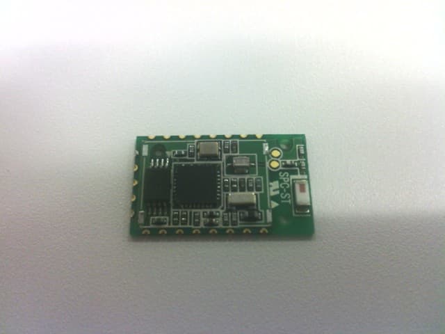
Click to zoom
Application Details
- Equipment Class
- DTS - Digital Transmission System
- Date of Grant
- Aug 01, 2013
- Application Purpose
- Original Equipment
- Date of Application
- Aug 01, 2013
- Equipment Note
- JM1
- Frequency Range
- 2402.00000000 - 2480.00000000
- Company
- Aplix Corporation
- Country
- Japan
Documents & Files
Document Text
Text extracted from the exhibit documents filed with the FCC. Open a document above to read the original.
ID Label/Location Info
Label Location JM1L2S PCBA 22 x 13mm Shielding case 15 x 12 x 1.8mm Label on Shielding case 14 x 10mm Note: Since the device is very small, the statement of FCC 15.19(a) is written in product manual.
Internal Photos
Photo Top Top without sheild Photo Bottom
RF Exposure Info
UL Japan, Inc. Shonan EMC Lab. 1-22-3 Megumigaoka, Hiratsuka-shi, Kanagawa-ken, 259-1220 JAPAN Telephone: +81 463 50 6400 Facsimile: +81 463 50 6401 July 5, 2013 UL Japan, Inc. 1-22-3 Megumigaoka, Hiratsuka-shi, Kanagawa-ken, 259-1220 JAPAN FCC ID: O8CJM1L2S To whom it may concern, We, UL Japan, Inc., hereby declare that JM1, model : JM1L2S (FCC ID: O8CJM1L2S) of Aplix IP Holdings Corporation is exempt from RF exposure SAR evaluation as its output power meets the exclusion limits stated in FCC Part 2 §2.1093 and FCC radio frequency (RF) Exposure Guidelines in Supplement C to OET65. KDB 447498D01 (V05) has the following exclusion for portable devices: The 1g and 10g SAR test exclusion thresholds for 100 MHz to 6 GHz at test separation distances < 50 mm are determined by: [(measured maximum equivalent isotropic radiated power(mW))/(Minimum separation distance(mm))]•[ √ f (GHz)] < 3.0 for 1g SAR and <7.5 for 10g extremity SAR where • f(GHz) is the RF channel transmit frequency in GHz • Power and distance are rounded to the nearest mW and mm before calculation • The result is rounded to one decimal place for comparison The test exclusions are a pplicable only when the minimum test separation distance is < 50 mm and for transmission frequencies between 100 MHz and 6 GHz. When the minimum test separation distance is < 5 mm, a distance of 5 mm is applied to determine SAR test exclusion. This device f = 2.48 GHz, distance = 5mm (minimum separation distance: 5 mm was used in the calculation) and the measured maximum equivalent isotropic radiated power was 1.56 mW So for this device: 1.56 mW [measured maximum equivalent isotropic radiated power] / 5 mm [minimum separation distance] * ( √ 2.48) = 0.49 * caliculation: measured maximum equivalent isotropic radiated power = 10 ^ ( ( maximum peak output power [dBm] + antenna gain [dBi] ) / 10) = 10 ^ ( ( 1.43 [dBm] + 0.5 [dBi] ) / 10) *This is less than 3.0, so no SAR is required. Thank you for your attention to this matter. Go Ishiwata Manager of WiSE Japan, UL Verification Service
Test Report
Test report No. : 10022739S Page : 1 of 35 Issued date : July 5, 2013 FCC ID : O8CJM1L2S UL Japan, Inc. Shonan EMC Lab. 1-22-3 Megumigaoka, Hiratsuka-shi, Kanagawa-ken, 259-1220 JAPAN Telephone : +81 463 50 6400 Facsimile : +81 463 50 6401 RADIO TEST REPORT Test Report No.: 10022739S Applicant : Aplix IP Holdings Corporation Type of Equipment : JM1 Model No. : JM1L2S FCC ID : O8CJM1L2S Test regulation : FCC Part15 Subpart C: 2012 Test result : Complied 1. This test report shall not be reproduced in full or partial, without the written approval of UL Japan, Inc. 2. The results in this report apply only to the sample tested. 3. This sample tested is in compliance with the limits of the above regulation. 4. The test results in this test report are traceable to the national or international standards. 5. This test report must not be used by the customer to claim product certification, approval, or endorsement by any agency of the Federal Government. 6. The opinions and the interpretations to the result of the description in this report are outside scopes where UL Japan has been accredited. Date of test: June 28 - 30, 2013 Tested by: Shinichi Takano Engineer of WiSE Japan, UL Verification Service Approved by : Go Ishiwata Manager of WiSE Japan, UL Verification Service RTL02610 The testing in which "Non-accreditation" is displayed is outside the accreditation scopes in UL Japan. There is no testing item of "Non-accreditation". 13-EM-F0429 Test report No. : 10022739S Page : 2 of 35 Issued date : July 5, 2013 FCC ID : O8CJM1L2S UL Japan, Inc. Shonan EMC Lab. 1-22-3 Megumigaoka, Hiratsuka-shi, Kanagawa-ken, 259-1220 JAPAN Telephone : +81 463 50 6400 Facsimile : +81 463 50 6401 REVISION HISTORY Original Test Report No.: 10022739S Revision Test report No. Date Page revised Contents - (Original) 10022739S July 5, 2013 - - Test report No. : 10022739S Page : 3 of 35 Issued date : July 5, 2013 FCC ID : O8CJM1L2S UL Japan, Inc. Shonan EMC Lab. 1-22-3 Megumigaoka, Hiratsuka-shi, Kanagawa-ken, 259-1220 JAPAN Telephone : +81 463 50 6400 Facsimile : +81 463 50 6401 Contents Page SECTION 1: Customer information ..................................................................................... 4 SECTION 2: Equipment under test (E.U.T.) ....................................................................... 4 SECTION 3: Test specification, procedures & results ......................................................... 5 SECTION 4: Operation of E.U.T. during testing ................................................................. 8 SECTION 5: Conducted emission ........................................................................................ 9 SECTION 6: 6dB bandwidth & Occupied bandwidth (99%) ........................................... 10 SECTION 7: Maximum peak output power ...................................................................... 10 SECTION 8: Out of band emissions (Antenna port conducted) ....................................... 10 SECTION 9: Peak power density........................................................................................ 10 SECTION 10: Radiated emission........................................................................................ 11 Contents of APPENDIXES ................................................................................................... 13 APPENDIX 1: Data of Radio tests ...................................................................................... 14 APPENDIX 2: Test instruments ......................................................................................... 32 APPENDIX 3: Photographs of test setup ........................................................................... 33 Test report No. : 10022739S Page : 4 of 35 Issued date : July 5, 2013 FCC ID : O8CJM1L2S UL Japan, Inc. Shonan EMC Lab. 1-22-3 Megumigaoka, Hiratsuka-shi, Kanagawa-ken, 259-1220 JAPAN Telephone : +81 463 50 6400 Facsimile : +81 463 50 6401 SECTION 1: Customer information Company Name : Aplix IP Holdings Corporation Address : Shinjuku Eastside Square 13F 27-30, Shinjuku 6-chome, Shinjuku-ku, Tokyo, 160-0022 Japan Telephone Number : +81-50-3786-1702 Facsimile Number : +81-80-8462-0681 Contact Person : Isamu Shimosako SECTION 2: Equipment under test (E.U.T.) 2.1 Identification of E.U.T. Type of Equipment : JM1 Model Number : JM1L2S Serial Number : Refer to 4.2 in this report. Rating : DC3.3V Country of Mass-production : Japan, China, Taiwan, Korea Condition of EUT : Production prototype (Not for Sale: This sample is equivalent to mass-produced items.) Receipt Date of Sample : June 28, 2013 Modification of EUT : No modification by the test lab. 2.2 Product description Model: JM1L2S (referred to as the EUT in this report) is JM1. Clock frequency(ies) in the system : 16MHz, 32.768kHz <Radio part> Equipment type : Transceiver Frequency of operation : 2402-2480MHz Bandwidth : 79MHz Channel spacing : 2MHz Type of modulation : DSSS Antenna type : Chip Antenna gain : 0.5dBi Antenna connector type : None ITU code : F1D Operation temperature range : -20 to +75 deg.C FCC 15.31 (e) / 212 The RF transmitter has its own regulator. The RF transmitter is constantly provided voltage (DC1.35V) through the regulator regardless of input voltage. Therefore, the equipment complies with the requirement. FCC 15.203 / 212 The antenna is not removable from the EUT. Therefore, the equipment complies with the antenna requirement. Test report No. : 10022739S Page : 5 of 35 Issued date : July 5, 2013 FCC ID : O8CJM1L2S UL Japan, Inc. Shonan EMC Lab. 1-22-3 Megumigaoka, Hiratsuka-shi, Kanagawa-ken, 259-1220 JAPAN Telephone : +81 463 50 6400 Facsimile : +81 463 50 6401 SECTION 3: Test specification, procedures & results 3.1 Test specification Test specification : FCC Part 15 Subpart C: 2012, final revised on December 27, 2012 and effective January 28, 2013 Title : FCC 47CFR Part15 Radio Frequency Device Subpart C Intentional Radiators Section 15.207 Conducted limits Section 15…
Text truncated - open the document above for the full version.
Test Setup Photos
UL Japan, Inc. Shonan EMC Lab. 1-22-3 Megumigaoka, Hiratsuka-shi, Kanagawa-ken, 259-1220 JAPAN Telephone : +81 463 50 6400 Facsimile : +81 463 50 6401 APPENDIX 3: Photographs of test setup Conducted emission Front Side Test Report No. : 10022739S 33 of 35 UL Japan, Inc. Shonan EMC Lab. 1-22-3 Megumigaoka, Hiratsuka-shi, Kanagawa-ken, 259-1220 JAPAN Telephone : +81 463 50 6400 Facsimile : +81 463 50 6401 Radiated emission Front view Rear view (below 1GHz) Rear view (above 1GHz) Test Report No. : 10022739S 34 of 35 UL Japan, Inc. Shonan EMC Lab. 1-22-3 Megumigaoka, Hiratsuka-shi, Kanagawa-ken, 259-1220 JAPAN Telephone : +81 463 50 6400 Facsimile : +81 463 50 6401 Pre-check of the worst position X-axis Y-axis Z-axis END OF REPORT Test Report No. : 10022739S 35 of 35
Contact Information
Applicant
Takahiro Shirakawa(Corporate Officer)
Technical Contact
UL Japan, Inc.Go Ishiwata
[email protected]81-463-50-6400
1-22-3 Megumigaoka, Hiratsuka-shi · Kanagawa-ken · Japan
Test Firm
UL Japan, Inc. Shonan EMC EMC Lab.Tetsuya Hashimoto
Technical Specifications
| # | Rule Parts | Frequency Range | Power Output |
|---|---|---|---|
| 1 | 15C | 2.40 GHz - 2.48 GHz | 1.40 mW |
Other Applications from Aplix Corporation

O8CJM1L2L
Jun 30, 2015JM1
Equipment Class
DTS - Digital Transmission System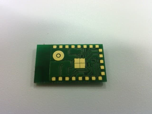
O8CJM1L2X
Dec 18, 2013JM1
Equipment Class
DTS - Digital Transmission System
O8CJM1L2
Feb 03, 2013JM1
Equipment Class
DTS - Digital Transmission System
O8CJM1V4
Sep 09, 2012JM1
Equipment Class
DSS - Part 15 Spread Spectrum Transmitter