O9BARVA9000Avalanche transceiver
ASTEELFLASH FRANCE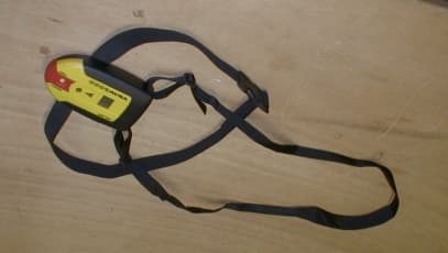
Click to zoom
Application Details
- Equipment Class
- DCD - Part 15 Low Power Transmitter Below 1705 kHz
- Date of Grant
- Mar 01, 2001
- Application Purpose
- Original Equipment
- Date of Application
- Nov 19, 2000
- Equipment Note
- Avalanche transceiver
- Frequency Range
- 0.45700000 - 0.45700000
- Company
- ASTEELFLASH FRANCE
- Country
- France
Documents & Files
Document Text
Text extracted from the exhibit documents filed with the FCC. Open a document above to read the original.
Users Manual
FCC ID: OB9ARVA9000 1 USER MANUAL This is a copy of the FCC statement provided to the user ; This statement will be included either in the documentation itself, or on a separate sheet which will be inserted in the documentation. Regulatory Information Notice for the USA: FCC State me nt Changes or modifications not expressly approved by Option Industries could void the user's authority to operate the eq uip me nt.
Users Manual
FCC ID: O9BARVA9000 1 USER'S MANUAL Here is a copy of the English user's manual: FCC ID: O9BARVA9000 FCC ID: O9BARVA9000 FCC ID: O9BARVA9000
Block Diagram
FCC ID: OB9ARVA9000 1 BLOCK DIAGRAM(S) OF EQUIPMENT 1.1 Clock list of ARVA9000 product Crystal: 4 MHz used for processor 3.656 MHz w hich gives 457 KHz after division 1.2 Block diagram Block diagram in emission mode: Block diagram in reception mode: Counter Coil antenna μ controller Buzzer Display Leds 3.656 MHz 457 KHz 4 MHz 70 ms On 0.9 s Off Coil antenna Pre amplifier Amplifier 457 KHz Filter μ Controller Buzzer Display Leds Ga in control 4 MHz 1.3 Modulation The 457 KHz signal is pulsed: width of the pulse is about 70 ms ON for 1 s OFF. The following plots show the signal modulation : Pulsed signal versus time, for a zero spanDetail of a previous pulse
Cover Letter(s)
FCC ID: OB9ARVA9000 1 COVER LETTER OPTION INDUSTRIES – ARVA9000 FCC ID: OB9ARVA9000 November 8, 2000 This report concerns : Original Grant ___ X ____Class II change __________ SubPart C certification ___ X ____ *Class A verification _______*Class I change _______ Equipment type : Low Power Transmitter Below 1705 KHz Request issue of grant : _ X _Immediately upon completion of review ___Defer grant per 47 CFR 0.457(d)(1)(ii) until ____ date _____. Company Name agrees to notify the Commission by _____date_____ of the intended date of announcement of the product so that the grant can be issued on that date. Confidentiality of grant : ___Applicant requests the existence of this grant to be kept confidential until ____date____. The announcement of this product before this date via freedom of information would be detrimental to Company Name, and therefore must be considered a business secret. Public announcement of this product will not be made prior to this date. (Max. 60 days after grant issued). Li mi ts used : (check one) CISPR 22 _______ ___________ Part 15 _______ X ___________ Measurement procedure used is ANSI C63.4-1992 unless another is specified. Other test procedure : ____________________________________________________ Application for verificationApplicant for this device Prepared by : Frank HAMELIN SMEE Actions Mesures ZI des Blanchisseries 38500 VOIRON – France Ph. : 33 4 76 65 76 50 Fax : 33 4 76 66 18 30 e-mail : [email protected] Jean Marc MOULIN OPTION INDUSTRIES ZI de Champ ROMAN 20, Rue de la tour de l'eau – BP307 38407 St MARTIN D'HERES – France Ph. : 33 4 76 63 33 50 Fax : 33 4 76 63 85 10 e-mail: [email protected] *Not to be filed with Equipment Authorization Branch of FCC unless requested Report format prepared by the Information Technology Industry Council (ITI) ESC-5 and reviewed by FCC staff in 1994
External Photos
FCC ID: OB9ARVA9000 1 EXTERNAL PHOTOS OF TESTED EUT Ge ne ral vie w Upper faceBottom face
ID Label/Location Info
FCC ID: OB9ARVA9000 1 PRODUCT LABELING 1.1 FCC ID Label This is the copy of the label stuck on the product 1.2 Location of label on EUT Label is stuck on the bottom face of the product (see picture). FCC ID: OB9ARVA9000 This device complies with part15 of the FCC rules Operatio n is s ubje ct to the fo llo wing two co nd itio ns : (1) This device may not cause harmful interference. (2) This device must accept any interference received, including interference that may cause undesired operation. 19 mm 38 mm
ID Label/Location Info
FCC ID: O9BARVA9000 1 PRODUCT LABELING 1.1 FCC ID Label This is the copy of the label stuck on the product 1.2 Location of label on EUT Label is stuck on the bottom face of the product (see picture). FCC ID: O9BARVA9000 This device complies with part15 of the FCC rules Operatio n is s ubje ct to the fo llo wing two co nd itio ns : (1) This device may not cause harmful interference. (2) This device must accept any interference received, including interference that may cause undesired operation. 19 mm 38 mm
Internal Photos
FCC ID: OB9ARVA9000 1 INTERNAL PHOTOS OF TESTED EUT 1 – Internal view, cover removed 2 – Internal board, upper face (small metallic cover re moved) FCC ID: OB9ARVA9000 3 – Internal board, detail 4 – Small board, detail5 – Small board, other face 6 – Small board, under quartz FCC ID: OB9ARVA9000 7 – Main board, display removed 8 – Main board, display, lighning and buzzer removed FCC ID: OB9ARVA9000 9 – Mai n boa rd, foil s i de
Operational Description
FCC ID: OB9ARVA9000 1 GENERAL INFORMATION 1.1 Product description The ARVA 9000 is a Beacon Digital Avalanche Transceiver. The ARVA 9000 is worn on body during mountains climbing or skiing; It emits a beep as long as it is set in S.O.S. mode. In case of somebody buried under an avalanche, a rescue person, can set its ARVA 9000 in receiver mode, locates the victim accurately under snow, and then extricates the victim. A multiple indicator, with automatic synchronization on the nearest victim, tells to the rescuers, when all victims have been rescued. The ARVA 9000 is automatically switch On when inserting the strap into the device. It works with 4 alkaline batteries which provide it, an autonomy of more than 250 hours. For more information, see product's data sheet at section 1.6. 1.2 Related Submittal(s) / Grant(s) All host equipment used in the test configuration are FCC granted, when relevant. 1.3 Tested System Details The FCC IDs for all equipment, plus description of all cables used in the tested system are : As no other equipment can be connected on the device, the tested system was only composed of the ARVA9000. Tra de Ma rk – Mo de l Numbe r (Se rial numbe r) FCC IDDe scri ptio nCa ble de scri ptio n Option Industries - ARVA9000* (sn: 3-B 4836) OB9ARVA9000 Beacon avalanche transceiverNo cable attached to product *Equipment Under Test 1.4 Test Methodology As the ARVA9000 can only work on batteries, no conducted testing has been performed. Radiated testing were performed according to the procedures in ANSI C63.4-1992, CISPR22-1993/A1:1995/A2:1996 and EN55022:1994/A1:1995/A2:1997. Radiated testing was performed at an antenna to EUT distance of 10 meters. During testing, the device under test has been moved in different positions in order to identify the worst case set-up. 1.5 Test facility Tests have been performed on November 6th, 2000. The test facility used to collect the radiated and conducted data is the SMEE Actions Mesures facility, located ZI des Blanchisseries, 38500 VOIRON, France. This test facility has been fully described in a report and accepted by FCC as compliant with the radiated and AC line conducted test site criteria in ANSI C63.4-1992 in a letter dated August 04, 1999 (registration number 94821). This test facility has also been accredited by COFRAC (French accreditation authority for European union test lab accreditation organization), accreditation number 1-0844 as compliant with test site criteria and competence in EN55022/CISPR22 norms for 89/336/EEC European EMC Directive application. All pertinent data for this test facility remains unchanged. FCC ID: OB9ARVA9000 1.6 Technical characteristics
Schematics
FCC ID: O9BARVA9000 1 SCHEMATICS Here is schematics of the ARVA9000: FCC ID: O9BARVA9000 FCC ID: O9BARVA9000 FCC ID: O9BARVA9000 FCC ID: O9BARVA9000
Test Report
FCC ID: OB9ARVA9000 1 TEST REPORT 1.1 System test configuration 1.1.1 Justification The system was configured for testing in a typical fashion (as a customer would normally use it). Both mode, SOS mode (ARVA emitting at 457 KHz) and rescue mode ( reception), have been tested during pre-scan evaluation; The ARVA 9000 in emission mode has been identified as the worst case, consequently, all test results contained in this report are from the ARVA 9000 set in SOS mode. The worst case position of the ARVA 9000 has been found in horizontal position, as shown on pictures of the setup. 1.1.2 EUT Exercise software The software used during testing is the one which is the one normally loaded in the product, and cannot be configured. The ARVA9000 is just set ON in emission mode. 1.1.3 Special accessories No special accessories were necessary to perform the test. The ARVA9000 is automatically switch ON, when strap is clipped on. 1.1.4 Equipment modifications No equipment modification has been necessary during testing to achieve compliance to FCC Part15, Subpart C levels. The unit tested was a production unit. 1.1.5 Configuration of tested system The EUT is set on the table in horizontal position, and turned On in emission mode. FCC ID: OB9ARVA9000 1.2 Conducted emission data As the ARVA9000 is powered with interna l batteries, no conducted emission test has been performed. 1.3 Radiated emission data 1.3.1 Test Procedure The product has been tested according to ANSI C63.4-1992 and FCC PART15, Subpart C. The product has been tested with 4 new alkaline AAA/LR03batteries, at a distance of 10 meters from the antenna and compared to the FCC PART15, Subpart C limits. Measurement bandwidth was 120 KHz from 30 MHz to 1 GHz, and 9KHz below 30 MHz. Requirements of 15.209 have been observed. Above 30MHz, antenna height search was performed from 1m to 4m for both horizontal and vertical polarization. Continuous linear turntable azimuth search was performed with 360 degrees range. Below 30MHz, a rod antenna has been used, according provisions of ANSI C63.4 (measurements distance is 10 meters and then extrapolated). The ARVA9000 has been moved in different positions in order to maximized emission. A summary of the worst case emissions found is show n on the following page. Test Equipme nt: HP-8574A E.M.I Receiver HP-8568B Analyzer + HP-85650 Quasi-Peak adapter + HP-85685A RF Preselector. EMCO 3104C Biconical Antenna & EMCO 3146 Log Periodic Antenna EMCO-1050, 6 meters height antenna mast & EMCO-1060, 3 meters diameter Turntable. HP-8591EM Spectrum analyser CHASE CBL6111A Antenna, 30-1000MHz AILTECH STODDART 94607-1, Active Rod Antenna ElectroMetrics Model RVR-30M, Passive Rod Antenna 1.3.2 Radiated emission data (30-1000MHz) Final result 30-1000 MHz Graph example - 30-1000MHz (3 meters measure ments in full anechoic chambe r) Due to the low levels measured at 3 meters in full anechoic chamber, no measurements above 30MHz has been performed on the open site. FCC ID: OB9ARVA9000 1.3.3 Radiated emission data (below 30 MHz) Final re sult be low 30 MHz Graph abstract – below 30 MHz (3 meters measurements in full anechoic chamber) Final result below 30 MHz measured on open site at 10 meters: Due to the low levels measured at 3 meters in full anechoic chamber, only the fundamental frequency has been performed on the open site. Frequency (MHz) Avera ge Limit (dBμV/m) Average (dBμV/m) Average-Limit (dB) Angle (deg) PolTot Corr (dB) 457 KHz44.435.2-9.270V20.5 1.3.4 Field Strength Calculation The field strength is calculated by adding the Antenna Factor and Cable Factor, and subtracting the Amplifier Gain (if any) from the measured reading. The basic equation with a sample calculation is as follow : FS = RA + AF + CF – AG WhereFS = Field Strength RA = Receiver Amplitude AF = Antenna Factor CF = Cable Factor AG = Amplifier Gain Assume a receiver reading of 52.5dBμV is obtained. The antenna factor of 7.4 and a cable factor of 1.1 is added. The amplifier gain of 29dB is subtracted, giving a field strength of 32 dBμV/m. FS = 52.5 + 7.4 + 1.1 – 29 = 32 dBμV/m The 32 dBμV/m value can be mathematically converted to its corresponding level in μV/m. Level in μV/m = Common Antilogarithm [(32dBμV/m)/20] = 39.8 μV/m.
Test Report
FCC ID: O9BARVA9000 1.1 Radiated emission data below 30 MHz 1.1.1 Test Procedure The product has been tested according to ANSI C63.4-1992 and FCC PART15, Subpart C. The product has been tested with 4 new alkaline AAA/LR03batteries, at a distance of 10 meters from the loop antenna and compared to the FCC PART15, Subpart C limits. Measurement bandwidth was 9KHz below 30 MHz. Requirements of 15.209 have been observed. The ARVA9000 has been moved in different positions in order to maximized emission. A summary of the worst case emissions found is show n on the following page. Below 30MHz, a loop antenna has been used in 2 polarization (axial and hortogonal), measurements distance was 10 meters. The average measure was compared to an extrapolated limit. At the intentional carrier frequency of 457 KHz, the limit at 300 meter is 2400/457=5.25 μV/m which is 14.4 dBμV/m. Using a 40 dB/decade factor, will extrapolate the limit to: 74.4 dBμV/m at 10 meters. Test Equipme nt: HP-8574A E.M.I Receiver HP-8568B Analyzer + HP-85650 Quasi-Peak adapter + HP-85685A RF Preselector. EMCO 3104C Biconical Antenna & EMCO 3146 Log Periodic Antenna EMCO-1050, 6 meters height antenna mast & EMCO-1060, 3 meters diameter Turntable. HP-8591EM Spectrum analyser CHASE CBL6111A Antenna, 30-1000MHz AILTECH STODDART 94607-1, Active Rod Antenna ElectroMetrics Model RVR-30M, Passive Rod Antenna HP-85462A Analyzer + HP-85460 Preselector SIDEN TELEC, Model CT2A, Loop Antenna 1.1.2 Radiated emission data (below 30 MHz) using a loop antenna Final re sult be low 30 MHz Graph abstract – below 30 MHz (3 meters measurements in full anechoic chamber – Peak detector) FCC ID: O9BARVA9000 Final result below 30 MHz measured on open site at 10 meters using loop antenna: Due to the low levels measured at 3 meters in full anechoic chamber, only the fundamental frequency has been measured on the open site. Frequency (MHz) Extrapolate Avera ge Limit (dBμV/m) Average measure (dBμV/m) Average-Limit (dB) Angle (deg) PolTot Corr (dB) 457 KHz74.447.8 -33.6 25Hortogonal57.1
Test Setup Photos
FCC ID: OB9ARVA9000 1 RADIATED AND CONDUCTED MEASUREMENT PHOTO 1.1 Radiated emission Front ViewRear View 1.2 Conducted emission No photos, because of no measure in conducted emission.
Contact Information
Applicant
Vanni Benjamin(Project manager)
Technical Contact
Option IndustriesJean-Marc Moulin
[email protected]33 4 76 63 33 50
Za Champ Roman · St Martin D'Heres · France
Test Firm
LCIE Sud-EstJacques Lorquin
Technical Specifications
| # | Rule Parts | Frequency Range | Power Output |
|---|---|---|---|
| 1 | 15C | 0.457 MHz - 0.457 MHz | - |
Other Applications from ASTEELFLASH FRANCE
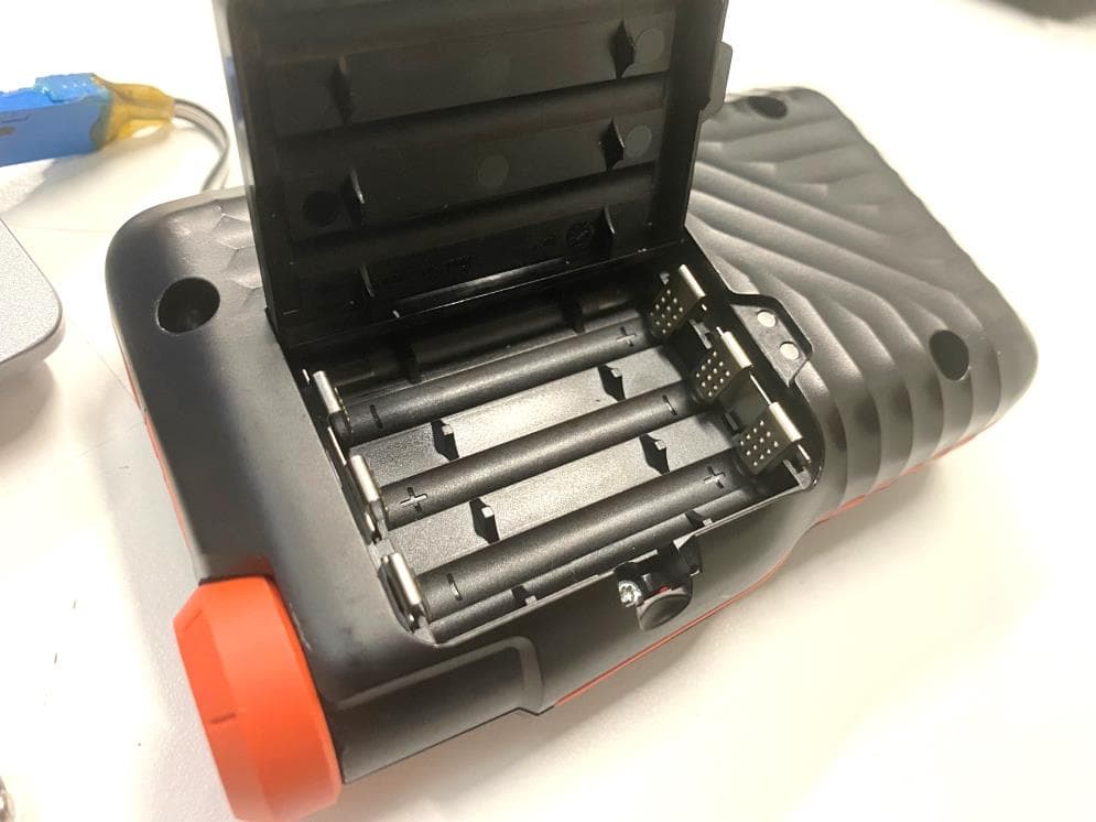
O9BARVAEVOBT
Feb 07, 2024AVALANCHE BEACON
Equipment Class
DCD - Part 15 Low Power Transmitter Below 1705 kHz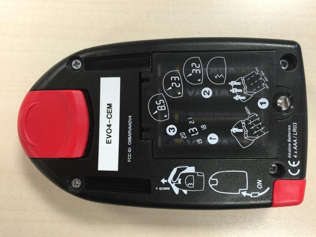
O9BARVAADV4
May 14, 2015Low Power Transmitter Below 1705 kHz
Equipment Class
DCD - Part 15 Low Power Transmitter Below 1705 kHz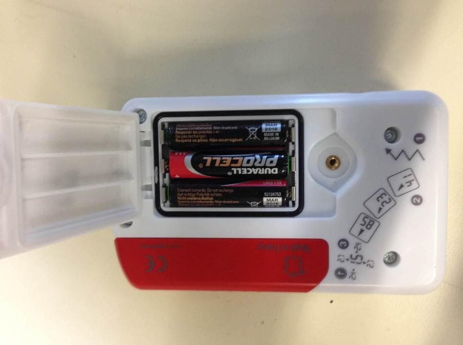
O9BARVANEO
Jul 08, 2014Low Power Transmitter Below 1705 kHz
Equipment Class
DCD - Part 15 Low Power Transmitter Below 1705 kHz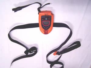
O9BARVAADV
Feb 06, 2005Avalanche Beacon
Equipment Class
DCD - Part 15 Low Power Transmitter Below 1705 kHz